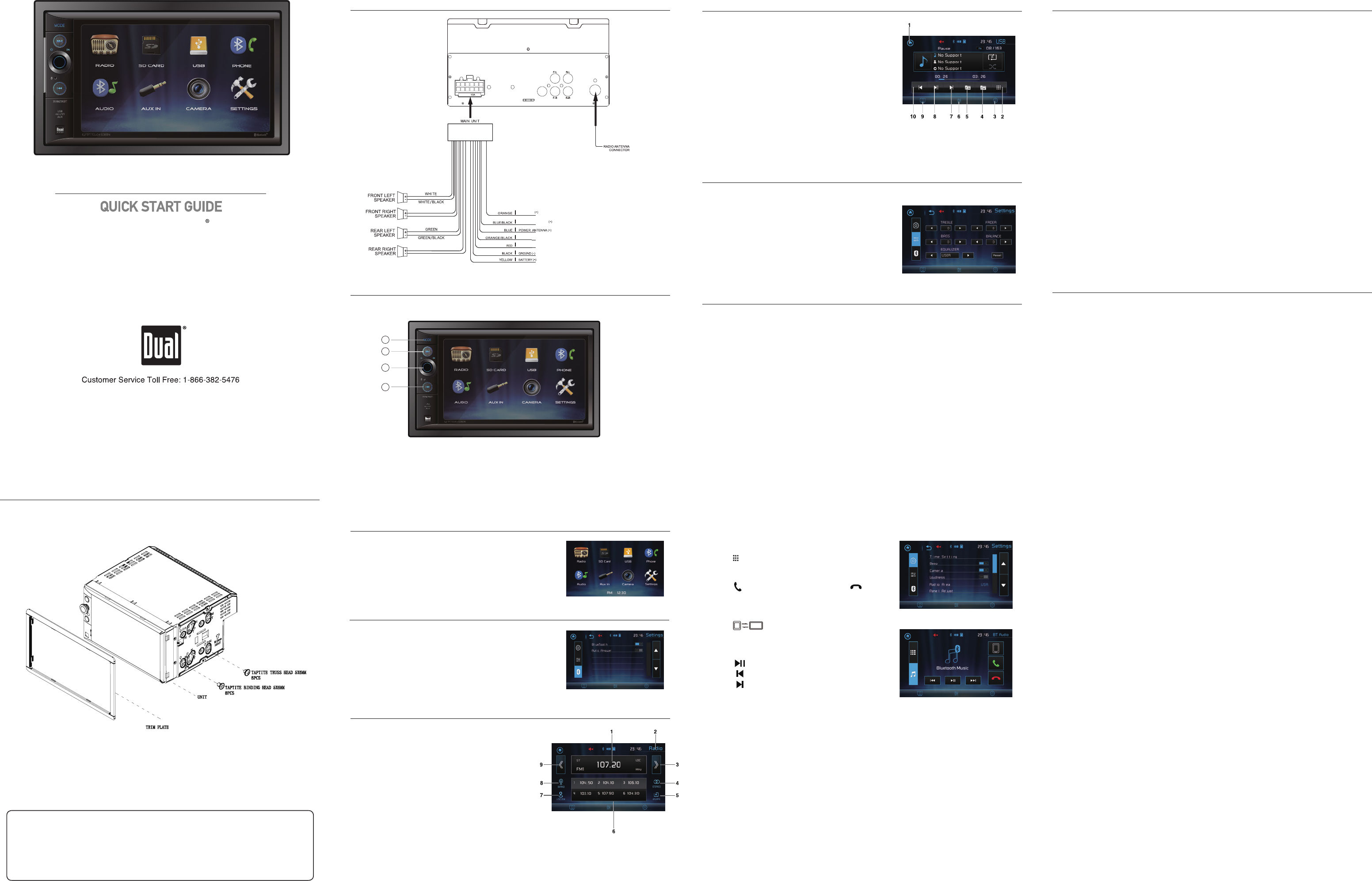
The Dual XVM296BT wiring diagram is a detailed schematic that outlines the electrical connections for the Dual XVM296BT multimedia receiver. It contains color-coded wires and clear instructions, making it easier to install the receiver in a vehicle’s dashboard.
The wiring diagram is essential for a successful installation, as it ensures that all the necessary connections are made correctly. It also helps prevent electrical damage or malfunctions. For instance, if the wiring diagram is not followed correctly, the receiver may not power on or certain features may not function properly.
The development of wiring diagrams for aftermarket car audio components, such as the Dual XVM296BT, has greatly simplified the installation process for enthusiasts and professional installers alike. These diagrams have become an industry standard, providing clear and comprehensive instructions for connecting various components within a vehicle’s electrical system.
The Dual XVM296BT Wiring Diagram is a crucial document that provides detailed instructions on how to connect the multimedia receiver to a vehicle’s electrical system. Understanding the various aspects of the wiring diagram is essential for a successful installation. Here are nine key aspects to consider:
- Color-coded wires: The wiring diagram uses color-coded wires to simplify the installation process. Each color corresponds to a specific function, such as power, ground, speakers, and antenna.
- Wire gauge: The wire gauge refers to the thickness of the wires. Thicker wires can handle more current and are used for high-power applications, while thinner wires are used for low-power applications.
- Fuse ratings: Fuses are used to protect the electrical system from damage in the event of a short circuit. The wiring diagram specifies the correct fuse rating for each circuit.
- Grounding points: Proper grounding is essential for the proper functioning of the receiver. The wiring diagram identifies the designated grounding points in the vehicle.
- Antenna connection: The wiring diagram provides instructions on how to connect the receiver to the vehicle’s antenna.
- Speaker connections: The wiring diagram shows how to connect the receiver to the vehicle’s speakers.
- Power connections: The wiring diagram provides instructions on how to connect the receiver to the vehicle’s power supply.
- Accessory connections: The wiring diagram may also include instructions on how to connect the receiver to accessories, such as steering wheel controls or backup cameras.
- Troubleshooting: The wiring diagram can be used to troubleshoot any issues that may arise during the installation or operation of the receiver.
These aspects work together to provide a comprehensive guide for installing the Dual XVM296BT multimedia receiver. By carefully following the wiring diagram, installers can ensure a safe and successful installation.
The color-coded wires in the Dual XVM296BT wiring diagram play a crucial role in simplifying the installation process. Each color is assigned to a specific function, making it easy to identify and connect the corresponding wires. This color-coding system is a critical component of the wiring diagram, as it helps to prevent errors and ensures a secure and functional installation.
For example, the power wires are typically red, the ground wires are black, and the speaker wires are color-coded according to their channel (e.g., white for left front, green for right rear). By following the color-coded wires, installers can quickly and accurately connect the receiver to the vehicle’s electrical system.
The practical significance of this understanding lies in the ease and efficiency it brings to the installation process. Without the color-coding, installers would have to rely on trial and error or spend significant time tracing wires to determine their function. This could lead to mistakes and potential damage to the receiver or the vehicle’s electrical system.
In summary, the color-coded wires in the Dual XVM296BT wiring diagram are a critical component that simplifies the installation process, reduces the risk of errors, and ensures the proper functioning of the receiver.
Wire gauge
In the context of the Dual XVM296BT wiring diagram, understanding wire gauge is crucial for ensuring the proper functioning and safety of the installed system. The wire gauge determines the thickness of the wires used in the installation, which directly affects their ability to handle electrical current.
Thicker wires, with a lower gauge number, can carry more current without overheating or causing excessive voltage drop. This is essential for high-power applications, such as connecting the receiver to the vehicle’s battery or powering external amplifiers. Conversely, thinner wires, with a higher gauge number, are suitable for low-power applications, such as connecting speakers or control modules.
The Dual XVM296BT wiring diagram specifies the recommended wire gauge for each connection, based on the expected current draw. Using wires with the correct gauge ensures that the system operates safely and efficiently, minimizing the risk of electrical problems or damage to the receiver or other components.
For example, the power wire connecting the receiver to the battery typically requires a thicker gauge wire, such as 12 or 14 AWG, to handle the higher current draw. On the other hand, speaker wires typically use a thinner gauge, such as 16 or 18 AWG, as they carry less current.
By understanding and adhering to the wire gauge specifications in the Dual XVM296BT wiring diagram, installers can ensure that the receiver is properly connected and functions optimally, enhancing the overall audio experience in the vehicle.
Fuse ratings
In the context of the Dual XVM296BT wiring diagram, understanding fuse ratings is critical for ensuring the safety and proper functioning of the installed system. Fuses are designed to protect the electrical system from damage caused by excessive current flow, which can occur in the event of a short circuit or other electrical fault.
The wiring diagram specifies the correct fuse rating for each circuit in the receiver’s electrical system. This rating is determined based on the maximum current draw expected for that particular circuit. Using fuses with the correct rating ensures that they will blow and interrupt the circuit in the event of excessive current flow, protecting the receiver and other components from damage.
For example, the power wire connecting the receiver to the battery typically requires a higher fuse rating, such as 10 or 15 amps, to protect against the higher current draw. On the other hand, speaker wires typically use a lower fuse rating, such as 2 or 5 amps, as they carry less current.
Using fuses with incorrect ratings can have serious consequences. If the fuse rating is too low, it may blow prematurely, interrupting the circuit even under normal operating conditions. Conversely, if the fuse rating is too high, it may not blow in the event of a short circuit, allowing excessive current to flow and potentially causing damage to the receiver or other components.
Therefore, it is crucial to follow the fuse rating specifications provided in the Dual XVM296BT wiring diagram. By using the correct fuses, installers can ensure that the electrical system is protected from damage and that the receiver operates safely and reliably.
Grounding points
Within the context of the Dual XVM296BT wiring diagram, grounding points play a crucial role in ensuring the proper functioning of the receiver. Grounding refers to the electrical connection of a circuit to a common reference point, typically the chassis of the vehicle. This connection provides a path for electrical current to flow, completing the circuit and allowing the receiver to operate correctly.
The wiring diagram identifies the designated grounding points in the vehicle, which are specifically chosen to provide a low-resistance connection to the chassis. These grounding points are often located near the receiver’s mounting location or along the vehicle’s frame. By connecting the receiver to these designated grounding points, installers ensure that the electrical current has a proper path to flow, minimizing noise, interference, and potential electrical issues.
For example, if the receiver is not properly grounded, it may experience issues such as intermittent operation, poor sound quality, or even damage to the receiver’s internal components. By following the wiring diagram and connecting the receiver to the designated grounding points, installers can avoid these problems and ensure that the receiver operates reliably and efficiently.
Furthermore, proper grounding is also essential for the safety of the electrical system. Without a proper ground connection, electrical current may take unintended paths, potentially causing damage to the vehicle’s electrical components or even posing a risk of electrical shock. By adhering to the grounding specifications in the wiring diagram, installers can ensure that the receiver is safely grounded and that the electrical system operates as intended.
In conclusion, grounding points are a critical component of the Dual XVM296BT wiring diagram, ensuring the proper functioning and safety of the receiver. By understanding the importance of grounding and following the wiring diagram’s specifications, installers can ensure that the receiver is properly connected and operates reliably, enhancing the overall audio experience in the vehicle.
Antenna connection
In the context of the Dual XVM296BT wiring diagram, the antenna connection is a critical component that enables the receiver to receive radio signals and provide audio entertainment to the vehicle’s occupants. The wiring diagram provides detailed instructions on how to connect the receiver to the vehicle’s antenna, ensuring optimal signal reception and sound quality.
The antenna connection involves identifying the correct antenna wire and connecting it to the designated terminal on the receiver. The wiring diagram typically uses color-coding or labels to clearly indicate the antenna wire and terminal, making the connection process straightforward. Proper antenna connection ensures that the receiver can pick up radio signals from nearby broadcasting stations, allowing users to enjoy a wide range of radio programs and music.
For example, in a typical vehicle installation, the antenna wire is usually located near the dashboard or A-pillar of the vehicle. The wiring diagram will specify the color and location of the antenna wire, and the installer simply needs to match it with the corresponding terminal on the receiver. Once the connection is made, the receiver can access the radio signals and provide audio entertainment.
Understanding the significance of the antenna connection in the Dual XVM296BT wiring diagram is essential for achieving optimal radio reception and sound quality in the vehicle. By following the wiring diagram’s instructions carefully, installers can ensure that the receiver is properly connected to the vehicle’s antenna, enabling users to enjoy their favorite radio programs and music with clarity and reliability.
In conclusion, the antenna connection in the Dual XVM296BT wiring diagram is a fundamental aspect that allows the receiver to receive and process radio signals. Proper antenna connection, as guided by the wiring diagram, ensures that users can fully utilize the receiver’s capabilities and enjoy a seamless audio experience in their vehicle.
Speaker connections
In the context of the Dual XVM296BT Wiring Diagram, understanding speaker connections is crucial for achieving optimal audio output and a fulfilling listening experience. The wiring diagram provides detailed instructions on how to connect the receiver to the vehicle’s speakers, ensuring proper signal transmission and sound reproduction.
- Types of Speaker Connections: The wiring diagram specifies the types of speaker connections supported by the receiver. Common connection types include high-level outputs for connecting to factory speaker wires and low-level outputs for connecting to aftermarket amplifiers.
- Speaker Wire Gauge: The wiring diagram indicates the recommended speaker wire gauge for optimal sound quality and performance. Using the correct wire gauge ensures efficient signal transmission and minimizes power loss.
- Speaker Polarity: The wiring diagram emphasizes the importance of maintaining proper speaker polarity to ensure correct sound reproduction. Connecting the positive terminal of the receiver to the positive terminal of the speaker, and the negative terminal of the receiver to the negative terminal of the speaker, is crucial for accurate sound imaging and tonal balance.
- Speaker Placement: While not directly addressed in the wiring diagram, speaker placement plays a significant role in overall sound quality. The wiring diagram’s instructions for speaker connections provide a foundation for optimal speaker placement, allowing users to fine-tune their audio system for the best possible listening experience.
Understanding and adhering to the speaker connection guidelines outlined in the Dual XVM296BT Wiring Diagram are essential for maximizing the receiver’s audio capabilities. Proper speaker connections ensure accurate and immersive sound reproduction, allowing users to fully appreciate their favorite music and audio content.
Power connections
Within the context of the Dual XVM296BT Wiring Diagram, understanding power connections is crucial for ensuring the proper functioning of the receiver and its audio system components. The wiring diagram provides detailed instructions on how to connect the receiver to the vehicle’s power supply, ensuring a stable and reliable electrical connection.
Power connections in the Dual XVM296BT Wiring Diagram involve identifying the correct power wires and connecting them to the designated terminals on the receiver. The wiring diagram typically uses color-coding or labels to clearly indicate the power wires and terminals, making the connection process straightforward. Proper power connections ensure that the receiver receives the necessary electrical current to operate its internal circuitry, amplify audio signals, and power connected speakers.
For instance, in a typical vehicle installation, the power wires are usually located near the fuse box or ignition switch. The wiring diagram will specify the color and location of the power wires, and the installer simply needs to match them with the corresponding terminals on the receiver. Once the power connections are made, the receiver can power up and access its various features and functions.
Understanding the significance of power connections in the Dual XVM296BT Wiring Diagram is essential for achieving optimal performance and reliability of the audio system. By following the wiring diagram’s instructions carefully, installers can ensure that the receiver is properly connected to the vehicle’s power supply, enabling users to enjoy high-quality audio entertainment without electrical issues or interruptions.
Accessory connections
Accessory connections play a crucial role in enhancing the functionality and user experience of the Dual XVM296BT multimedia receiver. The wiring diagram provides detailed instructions on how to connect various accessories, expanding the capabilities of the receiver beyond its core audio functions.
- Steering wheel controls: Integrating steering wheel controls with the receiver allows drivers to operate audio functions conveniently and safely while keeping their hands on the wheel. The wiring diagram guides the installer in connecting the receiver to the vehicle’s steering wheel control interface, enabling control over volume, track selection, and other functions.
- Backup cameras: Connecting a backup camera to the receiver enhances safety by providing a visual display of the area behind the vehicle when reversing. The wiring diagram includes instructions for connecting the camera to the receiver and setting up the necessary inputs and outputs for proper functionality.
- External amplifiers: For enthusiasts seeking a more powerful audio experience, the wiring diagram provides guidance on connecting external amplifiers to the receiver. By adding an amplifier, users can drive more powerful speakers and enjoy a louder, more immersive sound system.
- Other accessories: The wiring diagram may also cater to other accessories, such as Bluetooth microphones, satellite radio modules, or navigation devices. By providing instructions for these connections, the receiver can become a central hub for various entertainment and convenience features within the vehicle.
Accessory connections not only enhance the functionality of the Dual XVM296BT receiver but also contribute to a more integrated and enjoyable driving experience. By carefully following the wiring diagram’s instructions, installers can seamlessly connect these accessories, unlocking the full potential of the receiver and tailoring it to the specific needs and preferences of the vehicle owner.
Troubleshooting
The troubleshooting section of the Dual XVM296BT Wiring Diagram serves as an invaluable tool for installers and users alike, providing a systematic approach to diagnosing and resolving issues that may arise during the installation or operation of the receiver. Its importance stems from the intricate nature of car audio systems, where various components and connections must work in harmony to deliver optimal performance.
The wiring diagram not only provides a detailed visual representation of the receiver’s electrical connections but also includes specific troubleshooting tips and guidance. These instructions empower users to identify potential issues, such as incorrect wire connections, faulty components, or software glitches, and guide them through the necessary steps to rectify the problems.
For instance, if the receiver fails to power on after installation, the wiring diagram can help trace the issue back to a loose connection, a blown fuse, or a faulty power wire. By systematically checking each connection and component according to the diagram, installers can quickly pinpoint the source of the problem and implement the appropriate solution.
Furthermore, the troubleshooting section of the wiring diagram is crucial for maintaining the long-term reliability and performance of the audio system. By identifying and resolving issues promptly, users can prevent minor problems from escalating into more significant and costly repairs. Regular maintenance and troubleshooting, guided by the wiring diagram, ensure that the receiver and the entire audio system operate at their peak performance, delivering an enjoyable and trouble-free listening experience.


Related Posts


