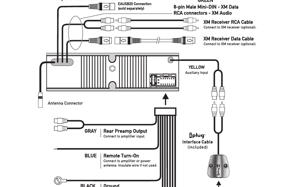
Dual XDM16BT Wiring Diagram: A wiring diagram that provides detailed instructions on how to connect the Dual Xdm16bt receiver to a vehicle’s electrical system. It outlines the color-coded wires and their corresponding functions, enabling proper installation and operation of the receiver.
This wiring diagram is essential for ensuring the receiver’s compatibility with the vehicle, preventing damage to the receiver or vehicle’s electrical components. It also allows for customizing the receiver’s features by connecting it to additional accessories such as amplifiers or speakers.
Historically, wiring diagrams have become increasingly important with the advancement of automotive technology that incorporates complex electrical systems. They have played a crucial role in troubleshooting and repairing vehicle electrical issues. In the context of the Dual XDM16BT receiver, the wiring diagram serves as a crucial tool for seamless integration and optimal performance.
Understanding the essential aspects of “Dual Xdm16bt Wiring Diagram” is crucial for comprehensive knowledge and skillful handling of the topic. The term “Wiring Diagram” primarily functions as a noun, denoting a technical document that provides a visual representation of electrical connections. This understanding guides our exploration of the key aspects that encompass the concept of “Dual Xdm16bt Wiring Diagram”:
- Compatibility: Ensuring the receiver’s compatibility with the specific vehicle model.
- Electrical Safety: Outlining proper wiring practices to prevent electrical hazards.
- Power and Ground Connections: Identifying the correct wires for power and ground connections.
- Speaker Connections: Providing instructions on connecting speakers to the receiver.
- Accessory Connections: Enabling the integration of additional accessories such as amplifiers or subwoofers.
- Troubleshooting Guide: Including troubleshooting tips for resolving common issues.
- Wire Color Coding: Utilizing standardized wire color coding for easy identification.
- Connector Types: Specifying the types of connectors used for making connections.
- Installation Tips: Providing guidance for proper installation techniques.
- Safety Precautions: Emphasizing safety measures to be followed during installation.
These key aspects collectively contribute to the effective installation and operation of the Dual Xdm16bt receiver. They provide a roadmap for understanding the wiring process, ensuring electrical safety, and maximizing the receiver’s functionality. By delving into each aspect, we gain a deeper understanding of the intricacies involved in working with the Dual Xdm16bt Wiring Diagram.
Compatibility
Compatibility plays a pivotal role in the context of the Dual Xdm16bt Wiring Diagram. The receiver’s compatibility with the specific vehicle model is a critical determinant of successful installation and operation. The wiring diagram provides instructions tailored to the electrical system of the vehicle, ensuring that the receiver integrates seamlessly and functions as intended.
Without proper compatibility, issues can arise, such as incorrect power supply, speaker compatibility problems, or malfunctioning features. The wiring diagram addresses these concerns by providing vehicle-specific instructions, eliminating guesswork and potential hazards. For instance, if the wiring diagram for a particular vehicle model specifies a specific wire color for the power connection, using a different wire can lead to electrical damage.
Understanding the importance of compatibility empowers individuals to make informed decisions when selecting and installing the Dual Xdm16bt receiver. By adhering to the vehicle-specific wiring diagram, users can ensure optimal performance, prevent electrical issues, and maximize the receiver’s capabilities. This understanding is essential for both professional installers and DIY enthusiasts alike.
Electrical Safety
Within the context of “Dual Xdm16bt Wiring Diagram”, electrical safety takes center stage, as improper wiring practices can lead to electrical hazards, posing risks to both the receiver and the vehicle’s electrical system. The wiring diagram serves as a crucial guide, outlining proper wiring techniques to prevent these hazards, ensuring a safe and reliable installation.
- Wire Gauge: The wiring diagram specifies the appropriate wire gauge for each connection, ensuring that the wires can handle the current draw of the receiver. Using undersized wires can lead to overheating, melting, and potential fires.
- Fuses and Circuit Breakers: The wiring diagram indicates the recommended fuse or circuit breaker ratings to protect the receiver and vehicle’s electrical system from overcurrent conditions. Improperly rated fuses or circuit breakers can fail to protect against electrical faults, leading to damage.
- Grounding: Proper grounding is essential for electrical safety. The wiring diagram provides instructions on how to connect the receiver’s ground wire to the vehicle’s chassis, ensuring a secure electrical connection and preventing electrical noise.
- Insulation and Protection: The wiring diagram emphasizes the importance of using insulated wires and protecting connections from moisture and abrasion. Exposed wires can lead to electrical shorts and other hazards.
Adhering to these electrical safety guidelines outlined in the “Dual Xdm16bt Wiring Diagram” is paramount. By following the specified wiring practices, individuals can minimize the risk of electrical hazards, ensuring the receiver’s safe operation and protecting the vehicle’s electrical system from damage.
Power and Ground Connections
Within the realm of “Dual Xdm16bt Wiring Diagram”, the identification of correct power and ground connections stands as a critical component. These connections serve as the lifeblood of the receiver, supplying the necessary electrical current for its operation and establishing a stable reference point for electrical circuits.
The wiring diagram plays a pivotal role in guiding users to the correct wires for power and ground connections. It specifies the wire colors and locations, ensuring that the receiver is connected to the vehicle’s electrical system in a safe and functional manner. Incorrect power or ground connections can lead to a range of issues, from minor malfunctions to catastrophic damage to the receiver or vehicle’s electrical system.
In practice, identifying the correct power and ground wires involves matching the wire colors specified in the wiring diagram to the actual wires in the vehicle. This often requires tracing the wires from the receiver’s harness to the vehicle’s fuse box or battery. It is crucial to double-check the connections using a multimeter to verify that the identified wires are indeed carrying power and ground.
Understanding the importance of power and ground connections is not limited to the installation of the Dual Xdm16bt receiver. It extends to any electrical or electronic device installed in a vehicle. Proper power and ground connections ensure the reliable operation of these devices, preventing electrical faults, damage, and potential hazards.
Speaker Connections
Within the context of “Dual Xdm16bt Wiring Diagram”, speaker connections play a vital role in completing the audio system installation and delivering the desired sound output. The wiring diagram provides detailed instructions on connecting speakers to the receiver, ensuring proper functionality and optimal sound quality.
Speaker connections involve matching the speaker wires to the corresponding terminals on the receiver and speakers. The wiring diagram specifies the wire colors and polarity (positive and negative) for each speaker channel, guiding users in making the correct connections. Incorrect speaker connections can result in distorted sound, reduced audio quality, or even damage to the receiver or speakers.
A real-life example of speaker connections within the “Dual Xdm16bt Wiring Diagram” is the installation of a four-speaker system. The wiring diagram would indicate the wire colors and terminals for the front left, front right, rear left, and rear right speakers, enabling the user to connect the speakers correctly.
Understanding the importance of speaker connections is essential for achieving the desired audio experience. Proper speaker connections ensure that the speakers are in phase, producing clear and balanced sound. Moreover, it prevents potential damage to the audio equipment and enhances the overall listening enjoyment.
In summary, speaker connections are a critical component of the “Dual Xdm16bt Wiring Diagram”, providing instructions for connecting speakers to the receiver safely and effectively. Understanding the principles and practices of speaker connections is crucial for maximizing the performance of the audio system, delivering high-quality sound reproduction, and preventing damage to the equipment.
Accessory Connections
Within the context of “Dual Xdm16bt Wiring Diagram”, accessory connections hold great significance, allowing users to enhance the functionality of their audio system by integrating additional accessories. The wiring diagram provides detailed instructions on connecting various accessories, such as amplifiers or subwoofers, to the receiver, enabling customization and a more immersive audio experience.
- Amplifier Connection: By connecting an external amplifier to the receiver via the designated pre-amp outputs, users can boost the power output, enhancing the overall volume and sound quality of the system. Amplifiers are particularly useful for driving subwoofers or powering multiple speakers, allowing for a more dynamic and impactful audio experience.
- Subwoofer Connection: The “Dual Xdm16bt Wiring Diagram” often includes instructions for connecting a subwoofer to the receiver. Subwoofers are dedicated speakers designed to reproduce low-frequency sounds, adding depth and bass response to the audio system. Connecting a subwoofer requires proper wiring to ensure it receives the appropriate signal and power from the receiver.
- High-Level Input Adapters: For vehicles that do not have dedicated pre-amp outputs, high-level input adapters can be used to connect the receiver to an amplifier. These adapters convert the speaker-level signals into pre-amp level signals, allowing for the integration of an amplifier into the system.
- Auxiliary Input Connections: The “Dual Xdm16bt Wiring Diagram” may also include instructions for connecting auxiliary devices, such as smartphones or MP3 players, to the receiver. Auxiliary input connections allow users to play audio from external sources through the vehicle’s audio system, expanding the entertainment options available.
Accessory connections empower users to customize their audio systems, tailoring them to their specific preferences and requirements. By understanding the principles and practices of accessory connections within the “Dual Xdm16bt Wiring Diagram”, individuals can unlock the full potential of their audio systems, enhancing their listening experience and enjoying a more immersive and dynamic sound.
Troubleshooting Guide
Within the context of “Dual Xdm16bt Wiring Diagram”, the troubleshooting guide serves as an invaluable tool for resolving common issues that may arise during or after the installation process. It provides a structured approach to diagnosing and rectifying problems, ensuring a seamless and optimal audio experience.
The troubleshooting guide is a critical component of the “Dual Xdm16bt Wiring Diagram”, as it empowers users to identify and address issues independently. Without a proper troubleshooting guide, users may encounter difficulties in diagnosing problems, leading to frustration and potentially incorrect attempts at repairs.
Real-life examples of troubleshooting tips within the “Dual Xdm16bt Wiring Diagram” include:
- No Power: If the receiver does not turn on, the troubleshooting guide may instruct users to check the power and ground connections, verify the fuse, or ensure the receiver is properly connected to the vehicle’s electrical system.
- No Sound: If there is no sound output from the speakers, the troubleshooting guide may suggest checking the speaker connections, verifying the speaker settings, or ensuring that the source device is properly connected.
- Distorted Sound: If the audio output is distorted, the troubleshooting guide may recommend checking the speaker wires for damage or loose connections, or adjusting the gain settings on the receiver.
Understanding the practical applications of the troubleshooting guide within the “Dual Xdm16bt Wiring Diagram” enables users to:
- Resolve common issues quickly and efficiently, reducing downtime and frustration.
- Avoid costly repairs by identifying and fixing problems before they escalate.
- Gain a deeper understanding of the receiver and its functionality, fostering self-reliance.
In summary, the troubleshooting guide included in the “Dual Xdm16bt Wiring Diagram” is a crucial resource for users, offering a systematic approach to resolving common issues, promoting self-sufficiency, and enhancing the overall audio experience. By leveraging the troubleshooting tips provided, users can maintain a well-functioning audio system and enjoy their music without interruptions or frustrations.
Wire Color Coding
Within the context of “Dual Xdm16bt Wiring Diagram”, wire color coding plays a critical role in simplifying the identification and connection of wires, ensuring a seamless and error-free installation process. Standardized wire color coding provides a common language for electrical professionals, enabling them to quickly and accurately identify the purpose of each wire.
The “Dual Xdm16bt Wiring Diagram” leverages this standardized color coding system, assigning specific colors to different types of wires. For example, in many vehicles, red wires typically indicate power connections, black wires represent ground connections, and blue wires are commonly used for accessory connections. By adhering to this color coding scheme, the wiring diagram makes it easier for users to distinguish between wires and connect them correctly.
Real-life examples of wire color coding within the “Dual Xdm16bt Wiring Diagram” include:
- Power wire: Red
- Ground wire: Black
- Front speaker wires: White (left positive), Gray (left negative), White/Black (right positive), Gray/Black (right negative)
- Rear speaker wires: Green (left positive), Green/Black (left negative), Purple (right positive), Purple/Black (right negative)
- Antenna wire: Blue
- Reverse gear wire: Pink
Understanding the practical applications of wire color coding within the “Dual Xdm16bt Wiring Diagram” empowers users to:
- Reduce installation time and effort by easily identifying wires.
- Minimize the risk of incorrect connections, preventing potential electrical issues.
- Simplify troubleshooting by allowing for quick identification of faulty wires.
In summary, wire color coding is a critical component of the “Dual Xdm16bt Wiring Diagram”, providing a standardized approach to wire identification. It streamlines the installation process, enhances safety, and facilitates troubleshooting. By comprehending the principles and applications of wire color coding within the wiring diagram, users can ensure a successful and efficient audio system installation.
Connector Types
Within the context of “Dual Xdm16bt Wiring Diagram”, connector types play a crucial role in ensuring secure and reliable electrical connections. The wiring diagram specifies the types of connectors used for making connections, providing precise guidance on the appropriate connectors for each wire and component. This ensures compatibility and proper functioning of the audio system.
Connector types are critical components of the “Dual Xdm16bt Wiring Diagram” because they determine the method of connecting wires to the receiver and other components. The diagram specifies the specific connectors required, such as RCA connectors for audio signals, spade connectors for power connections, and JST connectors for data connections. Using the correct connectors ensures a secure fit, prevents loose connections, and minimizes the risk of electrical hazards.
Real-life examples of connector types within the “Dual Xdm16bt Wiring Diagram” include:
- RCA connectors: Used to connect audio signals from the receiver to amplifiers or speakers.
- Spade connectors: Used to connect power wires to the receiver and fuse block.
- JST connectors: Used to connect the receiver to external devices, such as a Bluetooth module or USB adapter.
Understanding the practical applications of connector types within the “Dual Xdm16bt Wiring Diagram” empowers users to:
- Select the correct connectors for each connection, ensuring compatibility and reliability.
- Make secure and durable connections, minimizing the risk of electrical issues.
- Simplify the installation process by using the specified connectors, saving time and effort.
In summary, connector types are essential components of the “Dual Xdm16bt Wiring Diagram” as they define the method of connecting wires and components. By specifying the correct connectors, the wiring diagram ensures a secure and reliable audio system installation, minimizing the risk of electrical hazards and optimizing the system’s performance. Understanding the practical applications of connector types empowers users to make informed decisions and achieve a successful installation.
Installation Tips
Within the comprehensive scope of “Dual Xdm16bt Wiring Diagram”, “Installation Tips: Providing guidance for proper installation techniques” emerges as a critical component, offering invaluable guidance for a successful and efficient installation process. These tips empower users to approach the task with confidence, minimizing the risk of errors and ensuring optimal performance of the audio system.
- Planning and Preparation: Proper planning and preparation form the foundation for a successful installation. The installation tips provide detailed instructions on gathering the necessary tools and materials, selecting the appropriate mounting location, and ensuring compatibility with the vehicle’s electrical system.
- Wire Management: Managing wires effectively is crucial for a clean and organized installation. The diagram offers guidance on routing wires safely, securing them with zip ties or loom, and minimizing potential interference with other electrical components.
- Component Mounting: Mounting the receiver and other components securely ensures their stability and prevents damage during operation. The installation tips specify the recommended mounting locations, provide instructions for using brackets or screws, and emphasize the importance of vibration dampening.
- Testing and Troubleshooting: Before completing the installation, thorough testing and troubleshooting are essential to verify proper functionality. The installation tips guide users through testing procedures, identifying common issues, and providing troubleshooting techniques to resolve any problems.
By incorporating these installation tips into the “Dual Xdm16bt Wiring Diagram”, users gain a comprehensive understanding of the best practices and techniques for installing the audio system. This knowledge empowers them to achieve a professional-quality installation, maximizing the system’s performance, reliability, and longevity. Proper installation not only ensures a seamless audio experience but also contributes to the overall safety and integrity of the vehicle’s electrical system.
Safety Precautions
Within the comprehensive framework of “Dual Xdm16bt Wiring Diagram”, “Safety Precautions: Emphasizing safety measures to be followed during installation” stands as a crucial aspect, underscoring the paramount importance of adhering to established safety protocols to prevent potential hazards and ensure a secure installation process. These precautions serve as essential guidelines for both professional installers and DIY enthusiasts, empowering them to approach the task with the utmost care and attention to detail.
- Electrical Hazard Awareness: Recognizing and mitigating electrical hazards is of utmost importance. The precautions emphasize the need to disconnect the vehicle’s battery before commencing any electrical work, preventing the risk of electrical shocks or short circuits.
- Proper Tool Usage: Emphasizing the significance of using appropriate tools for the job, the precautions guide users in selecting the correct tools and equipment, ensuring the safe handling and manipulation of electrical components.
- Wiring Protection: To prevent electrical faults and potential fires, the precautions highlight the importance of protecting wires from damage during installation. This includes proper insulation, avoiding sharp bends, and securing wires away from heat sources.
- Grounding and Bonding: Ensuring proper grounding and bonding techniques is crucial for electrical safety. The precautions provide detailed instructions on grounding the receiver chassis to the vehicle’s frame, minimizing the risk of electrical noise and ensuring a stable electrical system.
By adhering to these safety precautions outlined in the “Dual Xdm16bt Wiring Diagram”, users can create a secure and reliable electrical installation, minimizing the potential for accidents or damage to the vehicle’s electrical system. These precautions not only safeguard the installer but also ensure the longevity and optimal performance of the audio system, contributing to an enjoyable and immersive listening experience. It is imperative to prioritize safety throughout the installation process, carefully following the specified guidelines and exercising due diligence to prevent any untoward incidents.


Related Posts


