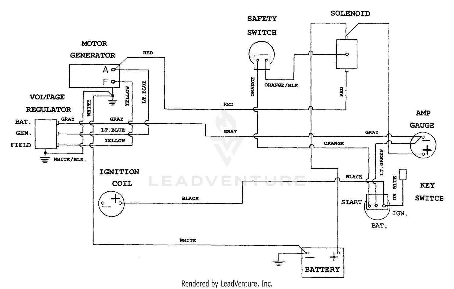
A Cub Cadet Wiring Diagram is a visual representation of the electrical system of a Cub Cadet lawn mower or garden tractor. It shows the location and function of electrical components, such as switches, lights, and motors.
Wiring diagrams are essential for troubleshooting electrical problems and for understanding how the electrical system works. They can also be used to plan modifications to the electrical system, such as adding new lights or accessories.
The first Cub Cadet wiring diagrams were created in the early 1960s. These diagrams were simple, hand-drawn schematics that showed the basic layout of the electrical system. Over time, wiring diagrams have become more complex to reflect the increasing number of electrical components used in Cub Cadet products.
Today, Cub Cadet wiring diagrams are created using computer-aided design (CAD) software. These diagrams are much more detailed than the early hand-drawn schematics and include information such as wire colors and connector pinouts.
The Cub Cadet Wiring Diagram is a vital tool for understanding and troubleshooting the electrical system of a Cub Cadet lawn mower or garden tractor. It provides a visual representation of the electrical components and their connections.
- Components: Switches, lights, motors, and other electrical devices.
- Connections: Wires, connectors, and terminals that connect the components.
- Layout: The physical arrangement of the electrical components.
- Function: The purpose of each electrical component and how it interacts with the other components.
- Troubleshooting: Identifying and repairing electrical problems.
- Modifications: Planning and implementing changes to the electrical system.
- Safety: Understanding the electrical system to avoid hazards.
- Documentation: Recording the electrical system for future reference.
- Training: Learning how to use and interpret the wiring diagram.
These aspects are all interconnected and essential for understanding the Cub Cadet Wiring Diagram. For example, the diagram shows the location of the electrical components, which is important for troubleshooting. The diagram also shows the connections between the components, which is important for understanding how the electrical system works. By understanding all of these aspects, you can use the wiring diagram to troubleshoot electrical problems, make modifications to the electrical system, and ensure the safe operation of your Cub Cadet lawn mower or garden tractor.
Components
The components of a Cub Cadet wiring diagram are the switches, lights, motors, and other electrical devices that make up the electrical system of a Cub Cadet lawn mower or garden tractor. These components are connected by wires and connectors, and they work together to power the mower or tractor and to control its operation.
The wiring diagram shows the location and function of each component, as well as the connections between the components. This information is essential for troubleshooting electrical problems and for understanding how the electrical system works. For example, if a light is not working, the wiring diagram can be used to identify the switch, fuse, and wiring that are associated with that light. This information can then be used to troubleshoot the problem and to make repairs.
The components of a Cub Cadet wiring diagram are critical to the operation of the mower or tractor. Without these components, the mower or tractor would not be able to start, run, or perform its intended functions. By understanding the function of each component and how it interacts with the other components, you can ensure that your Cub Cadet mower or tractor is operating safely and efficiently.
Here are some real-life examples of how the components of a Cub Cadet wiring diagram are used in practice:
- The switch is used to turn the mower or tractor on and off.
- The lights are used to illuminate the area around the mower or tractor when it is being operated in low-light conditions.
- The motor is used to power the mower or tractor’s blades and to drive the wheels.
- The other electrical devices, such as the battery, alternator, and starter, are used to power the mower or tractor’s electrical system and to start the engine.
By understanding the function of each component and how it interacts with the other components, you can troubleshoot electrical problems, make repairs, and ensure the safe and efficient operation of your Cub Cadet mower or tractor.
Connections
The connections between the components in a Cub Cadet wiring diagram are critical to the operation of the mower or tractor. These connections allow the electrical current to flow from the battery to the various components, such as the motor, lights, and switches. Without these connections, the mower or tractor would not be able to start, run, or perform its intended functions.
There are three main types of connections used in Cub Cadet wiring diagrams: wires, connectors, and terminals. Wires are used to carry the electrical current from one component to another. Connectors are used to join two or more wires together. Terminals are used to connect wires to the components.
It is important to ensure that all of the connections in a Cub Cadet wiring diagram are clean and tight. Loose or dirty connections can cause electrical problems, such as shorts, fires, and intermittent operation. When making a connection, it is important to use the correct type of wire, connector, and terminal.
Here are some real-life examples of how the connections in a Cub Cadet wiring diagram are used:
- The wires are used to connect the battery to the starter, the starter to the motor, and the motor to the ground.
- The connectors are used to join the wires together at the switch, the fuse block, and the light socket.
- The terminals are used to connect the wires to the battery, the starter, the motor, the switch, the fuse block, and the light socket.
By understanding the function of the connections in a Cub Cadet wiring diagram, you can troubleshoot electrical problems, make repairs, and ensure the safe and efficient operation of your Cub Cadet mower or tractor.
Layout
The layout of the electrical components in a Cub Cadet wiring diagram is critical to the operation of the mower or tractor. The layout determines the path that the electrical current will take from the battery to the various components, such as the motor, lights, and switches. A well-designed layout will minimize the length of the wires and the number of connections, which will reduce the risk of electrical problems.
There are several factors to consider when designing the layout of the electrical components in a Cub Cadet wiring diagram. These factors include:
- The location of the battery.
- The location of the motor.
- The location of the switches and controls.
- The length of the wires.
- The number of connections.
Once these factors have been considered, the electrical components can be arranged in a logical and efficient manner. The battery should be located as close to the motor as possible to minimize the length of the wires. The switches and controls should be located in a convenient location for the operator. The wires should be routed in a way that minimizes the risk of damage or interference.
Here are some real-life examples of how the layout of the electrical components in a Cub Cadet wiring diagram can affect the operation of the mower or tractor:
- If the battery is located too far from the motor, the voltage drop in the wires can cause the motor to run slowly or inefficiently.
- If the switches and controls are located in an inconvenient location, the operator may be more likely to make mistakes, which could lead to accidents.
- If the wires are routed in a way that makes them vulnerable to damage or interference, the mower or tractor could be more likely to experience electrical problems.
By understanding the importance of the layout of the electrical components in a Cub Cadet wiring diagram, you can ensure that your mower or tractor is operating safely and efficiently.
Function
The function of each electrical component in a Cub Cadet wiring diagram is critical to the operation of the mower or tractor. The electrical components work together to power the mower or tractor and to control its operation. By understanding the function of each component and how it interacts with the other components, you can troubleshoot electrical problems, make repairs, and ensure the safe and efficient operation of your Cub Cadet mower or tractor.
-
Power Source
The power source provides the electrical current that powers the mower or tractor. The power source can be a battery, an alternator, or a generator.
-
Controls
The controls allow the operator to control the operation of the mower or tractor. The controls can include switches, levers, and pedals.
-
Actuators
The actuators perform the physical actions that are required to operate the mower or tractor. The actuators can include motors, solenoids, and hydraulic cylinders.
-
Sensors
The sensors monitor the operating conditions of the mower or tractor. The sensors can include temperature sensors, pressure sensors, and speed sensors.
The electrical components in a Cub Cadet wiring diagram are all interconnected and interdependent. Each component plays a vital role in the operation of the mower or tractor. By understanding the function of each component and how it interacts with the other components, you can ensure that your Cub Cadet mower or tractor is operating safely and efficiently.
Troubleshooting
Troubleshooting electrical problems is a critical component of understanding and maintaining a Cub Cadet wiring diagram. When an electrical problem occurs, it is important to be able to identify the cause of the problem and repair it in a timely manner. The Cub Cadet wiring diagram provides a visual representation of the electrical system, which makes it easier to identify the location of the problem.
For example, if a light is not working, the wiring diagram can be used to identify the switch, fuse, and wiring that are associated with that light. This information can then be used to troubleshoot the problem and to make repairs. Without the wiring diagram, it would be much more difficult to identify the cause of the problem and to repair it.
In addition to identifying the cause of electrical problems, the Cub Cadet wiring diagram can also be used to repair the problems. The wiring diagram shows the location of the electrical components, as well as the connections between the components. This information can be used to replace faulty components and to repair damaged wires.
By understanding how to troubleshoot and repair electrical problems using the Cub Cadet wiring diagram, you can ensure that your Cub Cadet mower or tractor is operating safely and efficiently.
Modifications
The Cub Cadet Wiring Diagram is a critical tool for planning and implementing changes to the electrical system of a Cub Cadet lawn mower or garden tractor. The wiring diagram provides a visual representation of the electrical system, which makes it easier to identify the location of electrical components and to understand how they are connected.
For example, if you want to add a new light to your Cub Cadet mower, the wiring diagram can be used to identify the best location for the light and to determine how to connect the light to the electrical system. Without the wiring diagram, it would be much more difficult to add a new light to the mower, and you would be more likely to make a mistake that could damage the electrical system.
In addition to planning changes to the electrical system, the Cub Cadet Wiring Diagram can also be used to implement those changes. The wiring diagram shows the location of the electrical components, as well as the connections between the components. This information can be used to install new components and to modify the wiring as needed.
By understanding how to use the Cub Cadet Wiring Diagram, you can safely and easily make changes to the electrical system of your Cub Cadet mower or garden tractor. This can be a valuable skill, especially if you are planning to add new accessories or to modify the mower or tractor in any way.
Safety
Safety is of paramount importance when working with electrical systems, including those found in Cub Cadet lawn mowers and garden tractors. The Cub Cadet Wiring Diagram plays a crucial role in helping users understand the electrical system and identify potential hazards, thereby promoting safe operation and maintenance practices.
-
Electrical Shock
Electrical shock is a major hazard associated with electrical systems. The Cub Cadet Wiring Diagram helps identify components carrying high voltage, enabling users to take precautions to avoid accidental contact and potential injury.
-
Short Circuits
Short circuits can cause overheating, fires, and damage to electrical components. The Wiring Diagram aids in tracing wire paths and identifying potential short circuit points, allowing users to take preventive measures to ensure proper insulation and secure connections.
-
Ground Faults
Ground faults occur when electricity escapes from its intended path and flows through the ground. The Wiring Diagram helps pinpoint locations where proper grounding is essential to prevent electrical shocks, malfunctions, and equipment damage.
-
Overloading
Overloading an electrical system can lead to overheating, fires, and system failure. The Wiring Diagram assists in calculating electrical loads and ensuring proper wire sizing and circuit protection to prevent overloading conditions.
By understanding the electrical system through the Cub Cadet Wiring Diagram, users can proactively identify and mitigate potential hazards, reducing the risk of accidents, injuries, and property damage. It empowers them to perform maintenance tasks, troubleshoot electrical problems, and make modifications safely and effectively.
Documentation
The Cub Cadet Wiring Diagram serves not only as a troubleshooting and modification tool but also as a vital documentation resource for the electrical system of a Cub Cadet lawn mower or garden tractor. Proper documentation ensures that the electrical system is well-understood, maintained, and modified safely and effectively, both for current and future use.
-
Parts Identification and Inventory
The Wiring Diagram provides a comprehensive inventory of electrical components, including their location, function, and specifications. This documentation aids in identifying replacement parts, streamlining maintenance, and facilitating repairs by having accurate information readily available.
-
Modifications and Upgrades
When modifying or upgrading the electrical system, the Wiring Diagram serves as a reference point, allowing users to plan changes, anticipate potential issues, and ensure compatibility with existing components. Proper documentation of modifications helps maintain system integrity, safety, and functionality.
-
Troubleshooting History
The Wiring Diagram can be used to document troubleshooting efforts, including identified problems, steps taken, and solutions implemented. This history provides valuable insights for future troubleshooting, enabling users to learn from past experiences, avoid repeated issues, and maintain a reliable electrical system.
-
Compliance and Safety
Accurate documentation of the electrical system is essential for compliance with safety regulations and industry standards. It demonstrates a commitment to maintaining a safe working environment and helps prevent accidents, injuries, and property damage.
By investing time in documenting the electrical system using the Cub Cadet Wiring Diagram, users gain numerous benefits, including streamlined maintenance, informed modifications, efficient troubleshooting, and enhanced safety. It empowers them to take ownership of their equipment, extend its lifespan, and operate it with confidence.
Training
Training on using and interpreting wiring diagrams is a crucial aspect of understanding and maintaining the electrical system of a Cub Cadet lawn mower or garden tractor. This training empowers individuals to troubleshoot electrical problems, make modifications, and ensure the safe and efficient operation of their equipment.
-
Understanding Components and Symbols
Training involves familiarizing individuals with various electrical components, their symbols used in wiring diagrams, and their functions within the electrical system. This knowledge enables them to identify and locate components quickly and accurately.
-
Tracing Wire Paths
Learning to trace wire paths is essential for understanding the flow of electricity through the system. Training includes techniques for following wires, identifying connections, and understanding how different components are interconnected.
-
Troubleshooting Electrical Problems
Training covers systematic approaches to troubleshooting electrical problems using wiring diagrams. Individuals learn to identify potential issues, isolate faults, and determine appropriate repair strategies based on the diagram’s insights.
-
Safe Electrical Practices
Training emphasizes the importance of safety when working with electrical systems. It includes guidelines for handling electrical components, precautions to avoid shocks and hazards, and proper use of tools and equipment.
By acquiring these skills, individuals gain the confidence to maintain and modify Cub Cadet electrical systems effectively. This training enhances their ability to diagnose and resolve issues, reduces the risk of electrical accidents, and promotes the long-term reliability of their equipment.


Related Posts


