A Cub Cadet PTO switch wiring diagram is a technical document that outlines the electrical connections between the PTO switch and the tractor’s electrical system. It guides the user through the wiring process by providing a visual representation of the components and their connections.
The PTO switch wiring diagram is crucial for ensuring safe and proper PTO operation. By following the diagram, the user can connect the switch to the tractor’s electrical system correctly, ensuring that the PTO engages and disengages smoothly.
A key historical development in PTO switch wiring diagrams was the introduction of color-coded wiring. This simplified the wiring process, making it easier for users to identify the correct connections. Color-coded wiring also reduced the risk of errors, ensuring safe and reliable PTO operation.
The Cub Cadet PTO switch wiring diagram is a crucial document that provides detailed instructions on how to wire the PTO switch to the tractor’s electrical system. It ensures the safe and proper operation of the PTO, allowing the user to engage and disengage the PTO smoothly.
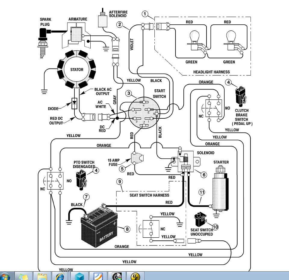
- Components: The wiring diagram identifies all the electrical components involved in the PTO switch circuit, including the switch itself, the PTO solenoid, and the tractor’s electrical system.
- Connections: The diagram clearly shows how each component is connected to the others, using color-coded wires for easy identification.
- Troubleshooting: The wiring diagram can be used for troubleshooting PTO switch issues by helping the user identify any breaks or shorts in the circuit.
- Safety: Following the wiring diagram correctly ensures that the PTO switch is wired safely, reducing the risk of electrical hazards.
- Efficiency: A properly wired PTO switch allows the PTO to engage and disengage quickly and efficiently, maximizing productivity.
- Compatibility: The wiring diagram is specific to the Cub Cadet tractor model, ensuring that the PTO switch is compatible with the tractor’s electrical system.
- Accuracy: The wiring diagram is created by Cub Cadet engineers, ensuring that it is accurate and reliable.
- Availability: The wiring diagram is readily available from Cub Cadet dealers and online resources, making it easy for users to obtain.
These aspects are essential for understanding the Cub Cadet PTO switch wiring diagram and ensuring its proper use. By understanding the components, connections, and safety considerations, users can confidently wire the PTO switch and maintain the tractor’s PTO system.
Components
The wiring diagram for a Cub Cadet PTO switch is a crucial document that provides detailed instructions on how to wire the PTO switch to the tractor’s electrical system. It ensures the safe and proper operation of the PTO, allowing the user to engage and disengage the PTO smoothly.
The components identified in the wiring diagram are all essential for the proper functioning of the PTO switch circuit. The switch itself is the main component that controls the engagement and disengagement of the PTO. The PTO solenoid is an electromagnetic device that actuates the PTO clutch, engaging or disengaging the PTO. The tractor’s electrical system provides the power to the PTO switch and solenoid.
A real-life example of the importance of understanding the components of the PTO switch circuit is when troubleshooting a malfunctioning PTO. By referring to the wiring diagram and identifying the specific components involved, a technician can quickly diagnose the issue and determine whether the problem lies with the switch, the solenoid, or the electrical system.
Practically, this understanding allows for efficient maintenance and repair of the PTO system. By knowing the components involved and their functions, technicians can quickly identify and resolve any issues, minimizing downtime and ensuring the optimal performance of the tractor.
In summary, the components identified in the Cub Cadet PTO switch wiring diagram are critical for the proper functioning of the PTO system. Understanding the relationship between these components allows for accurate troubleshooting, efficient repairs, and optimal tractor performance.
Connections
In the context of a Cub Cadet PTO switch wiring diagram, the connections between the components are critical for the proper functioning of the PTO system. The wiring diagram provides a clear visual representation of these connections, ensuring that the PTO switch is wired correctly and operates as intended.
For example, if the PTO switch is not connected to the PTO solenoid correctly, the PTO may not engage or disengage properly. This can lead to safety hazards and damage to the tractor or attached implements. By following the wiring diagram and making the connections correctly, the user can ensure that the PTO operates smoothly and reliably.
Another practical application of understanding the connections in the Cub Cadet PTO switch wiring diagram is troubleshooting. If the PTO is not functioning properly, the user can refer to the wiring diagram to identify the specific components that may be causing the issue. By checking the connections between these components, the user can quickly diagnose and resolve the problem, minimizing downtime and ensuring the optimal performance of the tractor.
In summary, the connections identified in the Cub Cadet PTO switch wiring diagram are critical for the proper functioning and troubleshooting of the PTO system. Understanding these connections allows users to wire the PTO switch correctly, identify and resolve issues quickly, and ensure the safe and efficient operation of the tractor.
Troubleshooting
In the context of a Cub Cadet PTO switch wiring diagram, the troubleshooting aspect is crucial for maintaining the proper functioning of the PTO system. This aspect empowers users to identify and resolve issues related to the PTO switch, ensuring the optimal performance and safety of the tractor.
- Identifying Breaks: The wiring diagram aids in identifying breaks in the circuit, which can disrupt the flow of electricity and prevent the PTO switch from functioning correctly. By following the diagram and testing for continuity, users can pinpoint the location of the break and repair it accordingly.
- Locating Shorts: Short circuits can also cause PTO switch malfunctions. The wiring diagram helps users identify potential short circuits by tracing the electrical connections. By eliminating short circuits, users can restore proper electrical flow and ensure the reliable operation of the PTO switch.
- Testing Components: The wiring diagram facilitates testing of individual components, such as the PTO switch itself, solenoids, and relays. By isolating each component and testing it according to the diagram, users can determine if a specific component is faulty and requires replacement.
- Tracing Wire Connections: The wiring diagram provides a visual representation of the wire connections, enabling users to trace the path of electricity through the circuit. This tracing helps identify loose or damaged connections that may cause intermittent PTO switch issues, allowing users to tighten or repair the connections as needed.
Troubleshooting the PTO switch using the wiring diagram empowers users to pinpoint and resolve electrical issues quickly and efficiently, minimizing downtime and ensuring the safe and reliable operation of the tractor’s PTO system.
Safety
In the context of “Cub Cadet PTO Switch Wiring Diagram,” safety is of utmost importance. Wiring the PTO switch correctly according to the diagram minimizes the risk of electrical hazards, ensuring the safety of the operator and the integrity of the tractor’s electrical system. Here are four key safety aspects to consider:
- Proper Grounding: The wiring diagram specifies the proper grounding points for the PTO switch circuit. Correct grounding prevents stray electrical currents from flowing through unintended paths, reducing the risk of electrical shocks or fires.
- Fuse Protection: The wiring diagram indicates the appropriate fuse sizes for the PTO switch circuit. Fuses protect the electrical system from overcurrents, preventing damage to components and potential electrical fires.
- Wire Gauge and Insulation: The wiring diagram specifies the correct wire gauge and insulation requirements for the PTO switch circuit. Adequate wire gauge ensures proper current carrying capacity, while proper insulation prevents short circuits and electrical leaks.
- Switch Rating: The wiring diagram ensures that the PTO switch is rated to handle the electrical load of the PTO system. Overloading the switch can lead to overheating, switch failure, or even electrical fires.
By following the Cub Cadet PTO Switch Wiring Diagram correctly, users can ensure the safe and reliable operation of the tractor’s PTO system, minimizing the risk of electrical hazards that could result in injury or equipment damage.
Efficiency
In the context of a Cub Cadet PTO switch wiring diagram, efficiency is paramount for optimizing the performance and productivity of the tractor’s power take-off (PTO) system. A properly wired PTO switch ensures that the PTO engages and disengages smoothly and promptly, allowing for efficient operation of PTO-driven implements and attachments.
The Cub Cadet PTO switch wiring diagram provides a precise guide for connecting the PTO switch to the tractor’s electrical system. By following the diagram and ensuring proper wiring, the user can minimize electrical resistance and power loss, resulting in efficient PTO operation. A well-wired PTO switch allows for quick and reliable engagement and disengagement of the PTO, reducing downtime and maximizing productivity.
For example, in agricultural applications, efficient PTO operation is critical for tasks such as operating mowers, tillers, and other implements. A properly wired PTO switch ensures that these implements can be engaged and disengaged quickly and efficiently, allowing farmers to cover more ground in less time. This efficiency translates into increased productivity and cost savings.
Furthermore, understanding the principles of PTO switch wiring and efficiency is essential for troubleshooting and maintenance. By analyzing the wiring diagram and identifying potential sources of inefficiency, technicians can diagnose and resolve issues promptly, minimizing downtime and ensuring optimal PTO performance.
In summary, the Cub Cadet PTO switch wiring diagram plays a crucial role in achieving efficiency in PTO operation. By providing a clear guide for proper wiring, the diagram enables users to optimize the performance of their tractors, maximize productivity, and ensure the efficient functioning of PTO-driven implements.
Compatibility
Within the context of “Cub Cadet PTO Switch Wiring Diagram,” compatibility plays a pivotal role in ensuring the proper functioning and safety of the tractor’s power take-off (PTO) system. The wiring diagram is meticulously designed to be specific to each Cub Cadet tractor model, guaranteeing seamless integration with the tractor’s unique electrical system.
- Electrical Specifications: Each Cub Cadet tractor model has specific electrical specifications, including voltage, amperage, and circuit configurations. The wiring diagram ensures that the PTO switch is compatible with these specifications, preventing electrical overloads, damage to components, and potential safety hazards.
- Connector Compatibility: The wiring diagram provides precise instructions on the types of connectors used in the PTO switch circuit. This ensures that the PTO switch can be securely connected to the tractor’s electrical system, preventing loose connections, intermittent operation, and potential electrical fires.
- Functional Integration: The wiring diagram outlines the specific functions of the PTO switch within the tractor’s electrical system. This ensures that the PTO switch can interact correctly with other electrical components, such as the PTO solenoid and safety interlocks, enabling reliable and safe PTO operation.
- Compliance with Standards: The wiring diagram adheres to industry standards and regulations, ensuring that the PTO switch installation meets safety and performance requirements. This compliance helps prevent accidents, protects the tractor and implements, and ensures optimal PTO performance.
In summary, the compatibility aspect of the Cub Cadet PTO switch wiring diagram is paramount for ensuring seamless integration with the tractor’s electrical system. By adhering to model-specific specifications, providing precise connector compatibility, outlining functional integration, and complying with standards, the wiring diagram guarantees safe, reliable, and efficient PTO operation.
Accuracy
In the context of the “Cub Cadet PTO Switch Wiring Diagram,” accuracy is paramount for ensuring the safe and reliable operation of the tractor’s power take-off (PTO) system. The wiring diagram is meticulously crafted by Cub Cadet engineers, guaranteeing its precision and dependability.
The accuracy of the wiring diagram directly influences the proper functioning of the PTO switch. An accurate diagram ensures that the PTO switch is wired correctly, preventing electrical hazards, damage to components, and potential accidents. It provides clear and precise instructions on the electrical connections, ensuring that the PTO switch interacts seamlessly with the tractor’s electrical system.
For example, in agricultural applications, accurate wiring of the PTO switch is crucial for operating PTO-driven implements such as mowers and tillers. A reliable wiring diagram ensures that the PTO engages and disengages smoothly, optimizing performance and productivity while minimizing downtime.
Furthermore, the accuracy of the wiring diagram is essential for troubleshooting and maintenance. Technicians rely on the diagram to diagnose electrical issues and identify faulty components. An accurate diagram enables quick and efficient troubleshooting, reducing repair time and ensuring optimal PTO performance.
In summary, the accuracy of the Cub Cadet PTO Switch Wiring Diagram is a critical component for the safe, reliable, and efficient operation of the tractor’s PTO system. By providing precise instructions and ensuring compatibility with the tractor’s electrical system, the accurate wiring diagram empowers users to wire the PTO switch correctly, troubleshoot issues effectively, and maximize the performance of their Cub Cadet tractor.
Availability
The availability of the Cub Cadet PTO switch wiring diagram is a critical aspect that enhances the usability and accessibility of the document. Its presence from Cub Cadet dealers and online resources ensures that users can easily obtain it whenever they need to wire or troubleshoot their PTO switch.
The easy availability of the wiring diagram empowers users to take control of their tractor’s maintenance and repairs. By having access to the diagram, they can perform wiring tasks with confidence, saving time and resources that would otherwise be spent on seeking professional assistance. This accessibility promotes self-reliance and reduces downtime, allowing users to keep their tractors operational with minimal disruptions.
For example, a farmer who needs to replace a faulty PTO switch can quickly obtain the wiring diagram from a nearby Cub Cadet dealer or download it from the company’s website. With the diagram in hand, they can follow the clear instructions to wire the new switch correctly, ensuring proper PTO operation without the need for costly service calls.
In summary, the availability of the Cub Cadet PTO switch wiring diagram plays a significant role in enabling users to maintain and repair their tractors efficiently. Its accessibility empowers users, reduces downtime, and promotes self-reliance, contributing to the overall productivity and cost-effectiveness of owning and operating a Cub Cadet tractor.


Related Posts


