A Cub Cadet Ignition Switch Wiring Diagram is a detailed plan that shows the electrical connections between the ignition switch and other components in a Cub Cadet lawn tractor or riding mower. The diagram identifies the wires by color and terminal number, and it shows how they are connected to the ignition switch, battery, starter solenoid, and other electrical components.
The wiring diagram is important because it provides a visual representation of the electrical system, making it easier to troubleshoot and repair problems. It can also be used to add new electrical components to the tractor or mower.
One key historical development in the design of Cub Cadet ignition switches was the introduction of the solid-state ignition module in the early 1970s. This module replaced the traditional points and condenser ignition system, and it provided a more reliable and efficient way to control the spark timing.
This article will provide a detailed overview of the Cub Cadet Ignition Switch Wiring Diagram, including its components, functions, and troubleshooting tips.
The Cub Cadet Ignition Switch Wiring Diagram is a crucial component of the electrical system in Cub Cadet lawn tractors and riding mowers. It provides a visual representation of the electrical connections between the ignition switch and other components, making it easier to troubleshoot and repair problems. The diagram also identifies the wires by color and terminal number, which can be helpful when adding new electrical components to the tractor or mower.
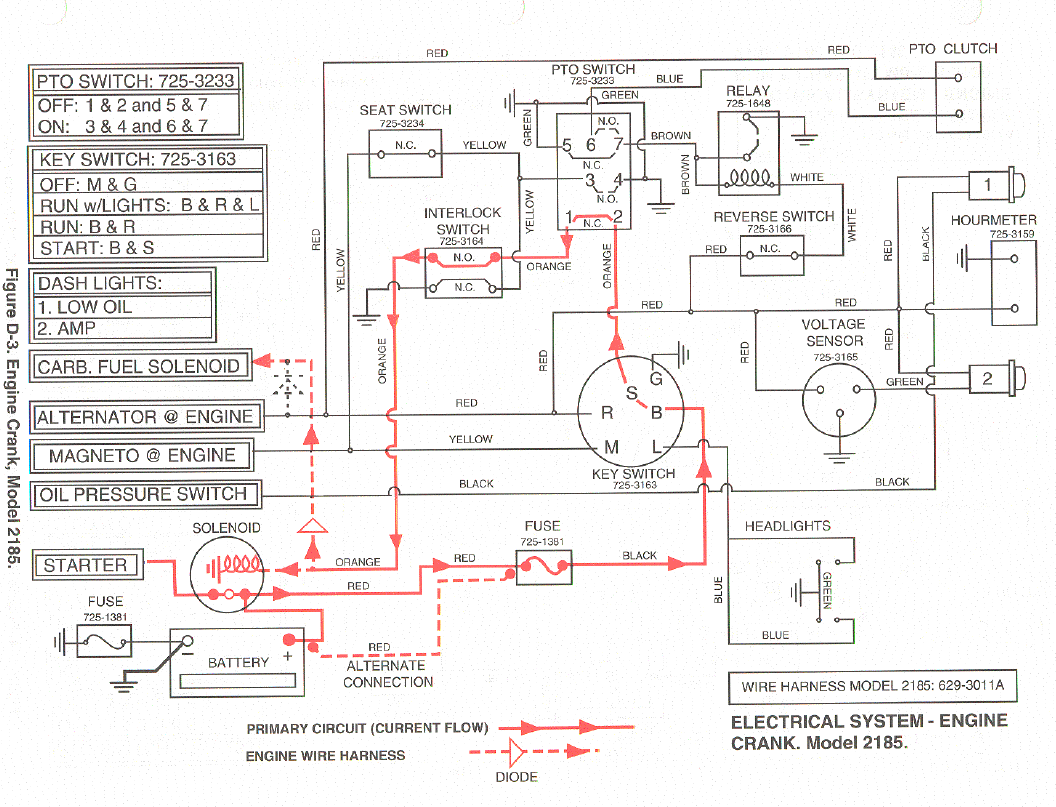
- Components: The diagram shows the ignition switch, battery, starter solenoid, and other electrical components.
- Connections: The diagram shows how the wires are connected to the ignition switch and other components.
- Troubleshooting: The diagram can be used to troubleshoot electrical problems by identifying the location of potential problems.
- Repair: The diagram can be used to repair electrical problems by providing a visual guide to the electrical system.
- Adding components: The diagram can be used to add new electrical components to the tractor or mower by providing information on how to connect the components.
- Solid-state ignition: The diagram shows the solid-state ignition module, which replaced the traditional points and condenser ignition system.
- Spark timing: The diagram shows how the ignition switch controls the spark timing.
- Safety: The diagram can be used to ensure that the electrical system is safe by identifying potential hazards.
- Maintenance: The diagram can be used to perform maintenance on the electrical system by providing information on how to clean and inspect the components.
These are just a few of the key aspects of the Cub Cadet Ignition Switch Wiring Diagram. By understanding these aspects, you can better troubleshoot and repair electrical problems on your Cub Cadet lawn tractor or riding mower.
Components
The Cub Cadet Ignition Switch Wiring Diagram provides a detailed overview of the electrical components in a Cub Cadet lawn tractor or riding mower. These components are essential for starting and operating the engine, and they must be connected correctly in order for the tractor or mower to run properly.
- Ignition switch: The ignition switch turns the electrical system on and off, and it also controls the spark timing. The ignition switch is typically located on the dashboard or control panel of the tractor or mower.
- Battery: The battery provides electrical power to the starter motor and other electrical components. The battery is typically located under the seat or behind the engine of the tractor or mower.
- Starter solenoid: The starter solenoid engages the starter motor when the ignition switch is turned to the “start” position. The starter solenoid is typically located on the starter motor.
- Other electrical components: The Cub Cadet Ignition Switch Wiring Diagram also shows other electrical components, such as the headlights, taillights, and horn. These components are powered by the battery and controlled by the ignition switch.
By understanding the components of the Cub Cadet Ignition Switch Wiring Diagram, you can better troubleshoot and repair electrical problems on your Cub Cadet lawn tractor or riding mower. You can also use the diagram to add new electrical components to your tractor or mower.
Connections
The connections between the ignition switch and other components are critical to the proper functioning of the Cub Cadet Ignition Switch Wiring Diagram. Without these connections, the ignition switch would not be able to control the flow of electricity to the starter solenoid, battery, and other electrical components. This would prevent the engine from starting and running properly.
Real-life examples of the connections between the ignition switch and other components include the following:
- The red wire from the ignition switch is connected to the positive terminal of the battery.
- The black wire from the ignition switch is connected to the negative terminal of the battery.
- The yellow wire from the ignition switch is connected to the starter solenoid.
- The green wire from the ignition switch is connected to the coil.
These connections allow the ignition switch to control the flow of electricity to the starter solenoid, battery, and other electrical components. This enables the engine to start and run properly.
Understanding the connections between the ignition switch and other components is important for troubleshooting and repairing electrical problems on Cub Cadet lawn tractors and riding mowers. By following the wiring diagram, you can identify the location of potential problems and make the necessary repairs.
Troubleshooting
Troubleshooting electrical problems on Cub Cadet lawn tractors and riding mowers can be a challenge, but it is made easier with the help of a Cub Cadet Ignition Switch Wiring Diagram. The diagram provides a visual representation of the electrical system, making it possible to identify the location of potential problems.
- Identify faulty components: The diagram can be used to identify faulty components by comparing the actual electrical connections to the diagram. If there is a discrepancy, it is likely that the component is faulty.
- Locate loose connections: Loose connections can cause electrical problems by preventing the flow of electricity. The diagram can be used to locate loose connections by checking the tightness of the wire connections.
- Identify shorts: Shorts occur when two wires come into contact with each other, causing a short circuit. The diagram can be used to identify shorts by checking the insulation of the wires.
- Trace wires: The diagram can be used to trace wires from one component to another. This can be helpful when troubleshooting problems with a specific component.
By understanding how to troubleshoot electrical problems using the Cub Cadet Ignition Switch Wiring Diagram, you can quickly and easily identify and repair problems with the electrical system on your Cub Cadet lawn tractor or riding mower.
Repair
The Cub Cadet Ignition Switch Wiring Diagram serves as an essential tool for repairing electrical problems by providing a visual representation of the electrical system. Through this diagram, users gain valuable insights into the interconnections between various components and can effectively troubleshoot and resolve any electrical malfunctions.
- Identification of faulty components: The diagram aids in pinpointing faulty components within the electrical system. By comparing the actual connections to the diagram, discrepancies can be identified, indicating potential issues with specific components.
- Correction of loose connections: Loose connections can lead to interruptions in the electrical flow and hinder the proper functioning of the system. The diagram allows users to locate and tighten loose connections, ensuring optimal electrical conductivity.
- Elimination of short circuits: Short circuits occur when two wires come into unintended contact, causing a disruption in the electrical current. By studying the diagram, users can identify potential areas where short circuits may occur and take appropriate measures to .
- Comprehensive troubleshooting: The diagram serves as a comprehensive guide for troubleshooting electrical problems. It provides a detailed overview of the system’s components and their interconnections, enabling users to trace wires, identify potential issues, and implement effective repairs.
In conclusion, the “Repair: The diagram can be used to repair electrical problems by providing a visual guide to the electrical system” aspect of the Cub Cadet Ignition Switch Wiring Diagram plays a crucial role in maintaining a well-functioning electrical system. By leveraging this diagram, users can efficiently diagnose and repair electrical issues, ensuring the optimal performance of their Cub Cadet equipment.
Adding components
The Cub Cadet Ignition Switch Wiring Diagram can guide users in the addition of new electrical components to their tractors or mowers by providing detailed instructions on how to connect these components. This aspect of the diagram serves as a valuable resource for customization and upgrades, allowing owners to enhance the functionality of their equipment.
- Identification of compatible components: The diagram assists in identifying electrical components compatible with the Cub Cadet system. It indicates the appropriate voltage, amperage, and other specifications to ensure seamless integration.
- Wiring instructions: The diagram provides step-by-step instructions on how to connect new electrical components to the existing wiring system. This includes guidance on wire routing, terminal crimping, and proper insulation techniques.
- Safety considerations: The diagram emphasizes safety precautions to be taken when adding electrical components. It highlights the importance of using proper tools, wearing appropriate protective gear, and following industry best practices.
- Troubleshooting assistance: The diagram can aid in troubleshooting any issues that may arise during the installation of new electrical components. By comparing the actual connections to the diagram, users can identify potential problems and make necessary adjustments.
In summary, the “Adding components: The diagram can be used to add new electrical components to the tractor or mower by providing information on how to connect the components” aspect of the Cub Cadet Ignition Switch Wiring Diagram empowers users to personalize and enhance their equipment. Through its comprehensive instructions and safety guidelines, the diagram ensures a smooth and efficient process, allowing users to confidently add new electrical components to their Cub Cadet tractors or mowers.
Solid-state ignition
The advent of solid-state ignition systems marked a significant advancement in the design and operation of Cub Cadet lawn tractors and riding mowers. Traditional points and condenser ignition systems, which relied on mechanical components to control spark timing, were replaced by solid-state ignition modules that utilized electronic components for greater precision and reliability.
The integration of solid-state ignition modules within the Cub Cadet Ignition Switch Wiring Diagram necessitated modifications to the electrical circuitry. The diagram reflects these changes, providing a detailed overview of the connections between the ignition switch, battery, starter solenoid, and other electrical components, including the solid-state ignition module. Understanding the relationship between the solid-state ignition module and the wiring diagram is crucial for troubleshooting and repairing electrical problems related to the ignition system.
Real-life examples of the solid-state ignition module within the Cub Cadet Ignition Switch Wiring Diagram can be observed in various Cub Cadet models. The diagram for a Cub Cadet XT1 Enduro LT42 lawn tractor, for instance, illustrates the connection of the solid-state ignition module to the ignition switch, battery, and starter solenoid. By following the wiring diagram, technicians can trace the flow of electricity through the ignition system and identify potential issues, such as loose connections or faulty components.
In summary, the solid-state ignition module is a critical component of the Cub Cadet Ignition Switch Wiring Diagram, representing a technological advancement that enhances the performance and reliability of the ignition system. Understanding the connection between solid-state ignition and the wiring diagram is essential for maintaining and repairing Cub Cadet lawn tractors and riding mowers, enabling technicians and users to troubleshoot and resolve electrical issues effectively.
Spark timing
Within the “Cub Cadet Ignition Switch Wiring Diagram,” the ignition switch plays a pivotal role in controlling spark timing, ensuring optimal engine performance and efficiency. The diagram provides a comprehensive overview of the ignition system, including how the ignition switch interacts with other components to regulate the timing of spark delivery to the engine’s cylinders.
-
Ignition coil:
The ignition coil, connected to the ignition switch, generates the high voltage necessary for spark production. The ignition switch controls the flow of current to the coil, determining the timing and duration of spark generation. -
Distributor cap and rotor:
The distributor cap and rotor distribute the high voltage from the ignition coil to the spark plugs in the correct firing order. The ignition switch initiates this process by sending a signal to the distributor. -
Spark plugs:
Spark plugs, located in the engine’s cylinders, create the spark that ignites the air-fuel mixture. The ignition switch, through the distributor, precisely controls the timing of spark delivery to each spark plug. -
Engine speed and load:
The ignition switch considers engine speed and load conditions to adjust spark timing. This ensures optimal combustion and engine performance under varying operating conditions.
Understanding spark timing control within the “Cub Cadet Ignition Switch Wiring Diagram” is crucial for troubleshooting ignition-related issues and maintaining engine efficiency. The diagram serves as a valuable tool for technicians and enthusiasts alike, providing insights into the intricate relationship between the ignition switch and the electrical components responsible for spark timing.
Safety
Within the context of the Cub Cadet Ignition Switch Wiring Diagram, prioritizing safety is paramount. The diagram serves as a valuable tool in identifying potential hazards and ensuring the electrical system’s safe operation. It provides insights into proper wiring techniques, component compatibility, and potential failure points, empowering users to mitigate risks and prevent electrical mishaps.
-
Grounding:
Ensuring proper grounding is crucial for electrical safety. The diagram indicates grounding points, ensuring that stray electrical currents are safely discharged, minimizing the risk of electrical shock or fire.
-
Fuse Protection:
The diagram identifies fuse locations and ratings, enabling users to select and install appropriate fuses. Fuses act as sacrificial components, safeguarding the electrical system from overcurrent conditions, preventing damage to components or even electrical fires.
-
Wire Gauge and Insulation:
The diagram specifies the appropriate wire gauge and insulation for each connection, preventing overheating and short circuits. Proper wire selection ensures that the electrical system can handle the required current without compromising safety.
-
Component Compatibility:
Understanding component compatibility is essential for safe operation. The diagram helps users identify compatible components, ensuring that they are electrically and physically compatible, preventing potential failures or hazards.
By understanding these safety aspects and meticulously following the Cub Cadet Ignition Switch Wiring Diagram, users can proactively prevent electrical hazards, ensuring the safe and reliable operation of their Cub Cadet equipment.
Maintenance
The Cub Cadet Ignition Switch Wiring Diagram is an essential tool for maintaining the electrical system of Cub Cadet lawn tractors and riding mowers. It provides detailed instructions on how to clean and inspect the electrical components, ensuring optimal performance and longevity. By following the diagram, users can identify potential problems early on and take proactive measures to prevent costly repairs.
Real-life examples of maintenance tasks guided by the Cub Cadet Ignition Switch Wiring Diagram include:
Cleaning battery terminals: Corrosion can build up on battery terminals over time, leading to poor electrical conductivity. The diagram shows how to safely remove and clean the terminals, ensuring a strong connection. Inspecting spark plugs: Worn or fouled spark plugs can cause ignition problems. The diagram provides guidance on how to remove and inspect spark plugs, identifying any issues that may need attention. Checking wire connections: Loose or damaged wire connections can disrupt the electrical flow. The diagram helps users locate and inspect wire connections, ensuring they are secure and properly insulated.
Understanding the connection between maintenance and the Cub Cadet Ignition Switch Wiring Diagram is critical for keeping the electrical system in good condition. By performing regular maintenance tasks guided by the diagram, users can extend the lifespan of their equipment and minimize the risk of electrical problems, contributing to the safe and efficient operation of their Cub Cadet machines.


Related Posts


