A Crutchfield Subwoofer Wiring Diagram guides the connection of a subwoofer to an audio system. For instance, a 4-ohm subwoofer requires a specific wiring configuration to match the amplifier’s impedance.
These diagrams are crucial for proper subwoofer integration, ensuring optimal sound quality, avoiding damage to components, and maximizing the system’s performance. A key historical development was the introduction of color-coded wires (e.g., red for positive, black for negative) to simplify the wiring process.
In this article, we will delve into the intricacies of Crutchfield Subwoofer Wiring Diagrams, exploring their components, variations, and the factors influencing their selection. We will also provide step-by-step instructions and troubleshooting tips to help you successfully install and connect your subwoofer for a dynamic and immersive audio experience.
Crutchfield Subwoofer Wiring Diagrams are pivotal in ensuring the proper integration of subwoofers into audio systems. Understanding the essential aspects of these diagrams is crucial for successful installation and optimal performance.
- Compatibility: Matching impedance and power handling of subwoofer and amplifier.
- Connections: Types and configurations of speaker wire connections (e.g., parallel, series).
- Polarity: Maintaining proper positive and negative connections for accurate sound reproduction.
- Wire Gauge: Selecting the appropriate wire thickness to minimize power loss.
- Grounding: Establishing a proper electrical ground for the system.
- Layout: Planning the physical placement of the subwoofer and wiring for optimal sound quality.
- Troubleshooting: Identifying and resolving common wiring issues (e.g., shorts, open circuits).
- Safety: Following proper safety precautions to prevent electrical hazards.
- Efficiency: Maximizing system efficiency through proper wiring techniques.
- Customization: Tailoring the wiring diagram to specific system requirements and preferences.
These aspects are interconnected, influencing the overall performance and reliability of the subwoofer system. Proper grounding ensures a stable electrical environment, while correct polarity prevents phase cancellation. Selecting the right wire gauge minimizes power loss, maintaining signal integrity. By considering these aspects, you can harness the full potential of your subwoofer and enhance your audio experience.
Compatibility
In the context of Crutchfield Subwoofer Wiring Diagrams, ensuring compatibility between the subwoofer and amplifier is of paramount importance. Impedance matching involves aligning the electrical resistance of the subwoofer with the amplifier’s output impedance. Mismatched impedance can lead to inefficient power transfer, distortion, and potential damage to components.
Crutchfield Subwoofer Wiring Diagrams provide clear guidelines for connecting subwoofers with different impedance ratings (e.g., 2 ohms, 4 ohms, 8 ohms) to amplifiers with varying output impedance. By following these diagrams, you can ensure that the subwoofer and amplifier are operating at their optimal levels, delivering maximum performance and longevity.
Real-life examples of compatibility matching in Crutchfield Subwoofer Wiring Diagrams include:
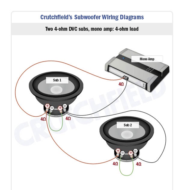
- Parallel Wiring: Connecting two 4-ohm subwoofers in parallel results in a 2-ohm load, which can be matched to a compatible amplifier with a 2-ohm stable output.
- Series Wiring: Connecting two 4-ohm subwoofers in series results in an 8-ohm load, which can be matched to a compatible amplifier with an 8-ohm stable output.
Understanding the relationship between compatibility and Crutchfield Subwoofer Wiring Diagrams empowers you to make informed decisions when designing and installing your audio system. By ensuring proper impedance matching and power handling, you can avoid potential issues, optimize performance, and enjoy a superior audio experience.
Connections
Within the framework of Crutchfield Subwoofer Wiring Diagrams, understanding the types and configurations of speaker wire connections is essential for achieving optimal performance and system reliability.
- Parallel Wiring: Connecting multiple subwoofers in parallel reduces the overall impedance of the circuit, allowing more current to flow. This configuration is suitable when the amplifier is stable at lower impedances (e.g., 2 ohms).
- Series Wiring: Connecting multiple subwoofers in series increases the overall impedance of the circuit, reducing the current flow. This configuration is suitable when the amplifier is stable at higher impedances (e.g., 8 ohms).
- Daisy Chaining: Connecting multiple subwoofers in a series-parallel configuration, daisy chaining allows for a combination of impedance matching and power distribution. This configuration is often used when multiple subwoofers of different impedances are used.
- High-Level Inputs: Some subwoofers offer high-level inputs, which connect to the speaker-level outputs of an amplifier or receiver. This type of connection simplifies wiring and allows for easy integration into existing systems.
The choice of speaker wire connection type depends on the impedance of the subwoofer(s), the stability of the amplifier, and the desired system performance. By carefully considering these factors and following the guidelines provided in Crutchfield Subwoofer Wiring Diagrams, you can ensure a proper and efficient connection between your subwoofer and amplifier.
Polarity
In the realm of Crutchfield Subwoofer Wiring Diagrams, understanding polarity is crucial for ensuring accurate sound reproduction and optimal system performance.
- Matching Terminals: Subwoofers and amplifiers have designated positive (+) and negative (-) terminals. Matching these terminals correctly ensures that the subwoofer cone moves in the intended direction, resulting in accurate bass response.
- Speaker Wire Polarity: Speaker wires also have polarity markings, typically indicated by colored insulation or ridges on one conductor. Connecting the positive terminal of the amplifier to the positive terminal of the subwoofer, and the negative to negative, maintains proper polarity.
- Phase Cancellation: Incorrect polarity can lead to phase cancellation, where the sound waves from the subwoofer and main speakers are out of sync, resulting in reduced bass output and muddy sound.
- Troubleshooting: If the bass sounds weak or distorted, checking the polarity of the connections is a key troubleshooting step. Reversing the polarity of the speaker wires can often resolve the issue.
Maintaining proper polarity in Crutchfield Subwoofer Wiring Diagrams is essential for achieving a cohesive and well-balanced sound system. By carefully observing polarity markings and connecting components accordingly, you can ensure that your subwoofer delivers its full potential and complements the main speakers, creating an immersive and enjoyable audio experience.
Wire Gauge
In the realm of Crutchfield Subwoofer Wiring Diagrams, selecting the appropriate wire gauge is essential to minimize power loss and ensure optimal system performance. Wire gauge refers to the thickness of the electrical wire used to connect components, measured in American Wire Gauge (AWG).
- Conductor Material: The type of conductor material, such as copper or aluminum, influences the wire’s resistance and power handling capabilities.
- Wire Length: Longer wire runs require thicker gauge wire to compensate for increased resistance and voltage drop.
- Power Requirements: Subwoofers with higher power handling capabilities require thicker gauge wire to accommodate the increased current flow.
- Impedance: The impedance of the subwoofer and amplifier combination also plays a role in determining the appropriate wire gauge, with lower impedance systems requiring thicker gauge wire.
Choosing the correct wire gauge ensures that the subwoofer receives adequate power, minimizing signal loss and distortion. It also prevents overheating and potential damage to the wiring and components. By carefully considering these factors and referring to Crutchfield Subwoofer Wiring Diagrams, you can select the appropriate wire gauge for your specific system configuration, ensuring efficient power transfer and optimal subwoofer performance.
Grounding
In the context of Crutchfield Subwoofer Wiring Diagrams, grounding plays a critical role in ensuring the proper functioning and safety of the audio system. Grounding refers to the establishment of a low-resistance electrical connection to the chassis of the vehicle or a dedicated grounding point, providing a reference point for electrical circuits and preventing potential electrical hazards.
Crutchfield Subwoofer Wiring Diagrams explicitly illustrate the grounding connection, typically represented by a black or bare wire. This wire connects the negative terminal of the amplifier (or subwoofer if it has an integrated amplifier) to a suitable grounding point on the vehicle’s chassis or a designated grounding location. By following these diagrams and ensuring a proper ground connection, you can prevent ground loops, reduce electrical noise, and protect your audio system from damage.
Real-life examples of grounding in Crutchfield Subwoofer Wiring Diagrams include connecting the negative terminal of a mono subwoofer amplifier to a grounding point on the vehicle’s chassis near the amplifier’s mounting location. Additionally, when using a distribution block to power multiple amplifiers, a single, heavy-gauge wire is used to connect the distribution block’s ground terminal to the vehicle’s chassis, ensuring a solid and reliable ground reference for all connected amplifiers.
Understanding the importance of grounding in Crutchfield Subwoofer Wiring Diagrams enables you to create a safe and reliable electrical foundation for your audio system. Proper grounding minimizes noise, prevents electrical malfunctions, and protects your equipment, ensuring optimal performance and longevity of your subwoofer system.
Layout
Layout planning plays a central role in the successful implementation of Crutchfield Subwoofer Wiring Diagrams. By carefully considering the physical placement of the subwoofer and the routing of the wiring, you can achieve optimal sound quality and system performance.
- Subwoofer Placement: The location of the subwoofer within the vehicle significantly impacts its sound reproduction. Factors such as cabin size, subwoofer type, and desired bass response should be considered when choosing a mounting location.
- Wiring Configuration: The layout of the wiring harness, including the length and gauge of the wires, can affect the overall performance of the subwoofer. Proper wire selection and routing minimize power loss and ensure efficient signal transfer.
- Isolation and Damping: Isolating the subwoofer from the vehicle’s frame and damping any potential resonances can reduce unwanted vibrations and improve sound quality. This involves using vibration-absorbing materials and securely mounting the subwoofer.
- Port Orientation: For ported subwoofers, the orientation of the port relative to the vehicle’s interior can influence the bass response. Experimenting with different port orientations can help optimize the subwoofer’s output in a specific acoustic environment.
By addressing these layout considerations and following the guidelines provided in Crutchfield Subwoofer Wiring Diagrams, you can optimize the performance of your subwoofer system, ensuring a dynamic and immersive audio experience. Proper planning and execution of the layout will pay dividends in terms of sound quality, reliability, and overall listening enjoyment.
Troubleshooting
Troubleshooting wiring issues is a critical component of Crutchfield Subwoofer Wiring Diagrams as it helps ensure the system’s proper functioning, safety, and optimal performance. Wiring issues, such as shorts and open circuits, can compromise the subwoofer’s sound quality, damage components, or even pose safety hazards.
The Crutchfield Subwoofer Wiring Diagram provides a detailed roadmap for connecting the subwoofer to the amplifier and power source. However, even with careful adherence to the diagram, issues may still arise due to various factors such as faulty wiring, loose connections, or external damage. Troubleshooting these issues requires a systematic approach and an understanding of basic electrical principles.
Real-life examples of troubleshooting wiring issues include identifying and repairing shorts, where two wires come into unintended contact, causing a direct path for current flow, and open circuits, where the electrical pathway is broken, interrupting the flow of current. By following the Crutchfield Subwoofer Wiring Diagram and using a multimeter to test for continuity and shorts, these issues can be pinpointed and resolved, ensuring the subwoofer operates as intended.
Understanding the connection between troubleshooting and Crutchfield Subwoofer Wiring Diagrams empowers users to maintain and repair their subwoofer systems, preventing potential problems and ensuring a seamless and enjoyable audio experience.
Safety
Within the context of Crutchfield Subwoofer Wiring Diagrams, following proper safety precautions is paramount to prevent potential electrical hazards and ensure the safe and reliable operation of your audio system. Electrical hazards, such as shorts, overloads, and improper grounding, can lead to component damage, electrical fires, or even personal injury if not addressed appropriately.
Crutchfield Subwoofer Wiring Diagrams play a critical role in promoting safety by providing clear and detailed instructions on how to correctly connect and configure your subwoofer system. These diagrams highlight essential safety measures, including proper wire selection, fuse protection, and grounding techniques. By adhering to these guidelines, you can minimize the risk of electrical hazards and ensure that your subwoofer operates as intended.
Real-life examples of safety precautions within Crutchfield Subwoofer Wiring Diagrams include specifying the appropriate fuse rating for the amplifier based on its power output, indicating the correct gauge of wire to use for power and ground connections, and emphasizing the importance of securely grounding the amplifier chassis to a suitable metal surface. These precautions help prevent overcurrent conditions, reduce the risk of electrical fires, and ensure that the subwoofer system is properly integrated into the vehicle’s electrical system.
Understanding the connection between safety precautions and Crutchfield Subwoofer Wiring Diagrams empowers you to make informed decisions during the installation and operation of your subwoofer system. By prioritizing safety and following the guidelines provided in these diagrams, you can enjoy your audio system with peace of mind, knowing that potential electrical hazards have been mitigated.
Efficiency
Within the context of Crutchfield Subwoofer Wiring Diagrams, understanding the principles of efficiency and applying proper wiring techniques are crucial for maximizing the performance of your audio system. By following the guidelines outlined in these diagrams, you can ensure that your subwoofer system operates at its optimal level, delivering exceptional sound quality while minimizing energy consumption and preserving the longevity of your components.
Crutchfield Subwoofer Wiring Diagrams provide detailed instructions on selecting the appropriate wire gauge, considering factors such as power handling, wire length, and impedance matching. By choosing the correct wire gauge, you can minimize power loss due to electrical resistance, ensuring that the subwoofer receives sufficient power to produce deep and impactful bass. Additionally, proper grounding techniques, as specified in the diagrams, help complete the electrical circuit and prevent potential ground loops, which can introduce noise and distortion into the audio signal.
Real-life examples of efficiency-maximizing wiring techniques include using a thicker gauge wire for longer wire runs to reduce resistance and maintain signal strength. Additionally, employing high-quality connectors and avoiding excessive bends or kinks in the wiring helps minimize signal degradation and ensures a reliable connection between components. By implementing these techniques, you can optimize the efficiency of your subwoofer system, resulting in improved sound quality, increased durability, and reduced power consumption.
Understanding the connection between efficiency and Crutchfield Subwoofer Wiring Diagrams empowers you to make informed decisions during the installation and operation of your audio system. By prioritizing efficiency and adhering to the guidelines provided in these diagrams, you can enjoy an enhanced audio experience, knowing that your subwoofer system is operating at its peak performance while conserving energy and extending the lifespan of your components.
Customization
Within the context of Crutchfield Subwoofer Wiring Diagrams, customization plays a pivotal role in adapting the wiring configuration to meet specific system requirements and preferences. This aspect encompasses various facets, empowering users to tailor their subwoofer setup to achieve optimal performance, aesthetics, and integration with existing components.
- Component Selection and Integration: Crutchfield Subwoofer Wiring Diagrams provide flexibility in selecting and integrating compatible components, such as amplifiers, subwoofers, and enclosures, based on individual system goals. This customization allows for personalized sound characteristics and seamless integration with the vehicle’s audio system.
- Signal Routing and Processing: Advanced diagrams offer options for signal routing and processing, enabling users to incorporate signal processors, crossovers, and equalizers into the subwoofer system. This level of customization allows for fine-tuning the subwoofer’s output, optimizing frequency response, and achieving desired sound effects.
- Aesthetic Considerations: For enthusiasts seeking a cohesive and visually appealing installation, Crutchfield Subwoofer Wiring Diagrams guide the integration of subwoofers and enclosures while considering aesthetic factors. This includes stealthy mounting options, custom enclosures, and color-coded wiring to maintain a clean and organized appearance.
- Compatibility and Troubleshooting: Customization extends to addressing compatibility issues and troubleshooting challenges. Diagrams provide guidance on adapting the wiring to match different subwoofer impedances, amplifier power outputs, and vehicle-specific electrical systems. This flexibility ensures compatibility and resolves potential issues during installation.
In summary, the customization aspect of Crutchfield Subwoofer Wiring Diagrams empowers users to tailor their subwoofer systems to specific requirements, preferences, and vehicle configurations. By leveraging this flexibility, enthusiasts can achieve optimized sound quality, seamless integration, and a personalized audio experience that meets their unique needs.


![[DIAGRAM] Single Subwoofer Wiring Diagram](https://i0.wp.com/images.crutchfieldonline.com/ca/learningcenter/car/subwoofer_wiring/1DVC_4-ohm_mono.jpg?w=665&ssl=1)
Related Posts


