A color wire 4-pin CB mic wiring diagram is a schematic representation of the wiring connections between a four-pin CB microphone and a compatible CB radio. Each wire is designated a specific color (e.g., red, black, blue, yellow) to indicate its intended function (e.g., ground, power, audio, PTT). For instance, in a typical 4-pin CB mic wiring setup, the red wire is used to transmit audio, the black wire for the ground connection, the blue wire for the power supply, and the yellow wire for the push-to-talk (PTT) function.
This wiring diagram is crucial for ensuring proper communication and functionality between the microphone and radio. It helps establish the necessary electrical connections for transmitting audio signals, receiving power, and activating the PTT feature. Understanding and adhering to the diagram’s guidelines minimize the risk of electrical issues or poor performance, enabling users to communicate effectively using their CB equipment.
A significant development in the history of CB mic wiring diagrams was the standardization of color codes for the different wire functions. This standardization, established through industry conventions and regulations, ensures consistency and interoperability between CB microphones and radios from various manufacturers. It simplifies the wiring process and allows users to replace or upgrade their equipment without encountering compatibility issues due to varying wire colors.
This article will delve deeper into the technical aspects and practical implications of color wire 4-pin CB mic wiring diagrams. We will examine the specific functions of each wire, discuss common troubleshooting tips, and provide guidance on selecting and installing compatible CB microphone wiring.
Understanding the essential aspects of “Color Wire 4 Pin CB Mic Wiring Diagram” is paramount for effective communication using CB radios. These aspects encompass various dimensions related to the diagram’s function, application, and technical details.
- Color Codes: Standardization of wire colors for specific functions ensures consistency and compatibility.
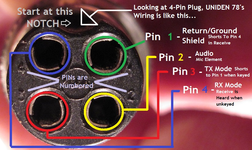
- Pin Configuration: Defines the arrangement and purpose of each pin on the 4-pin connector.
- Grounding: Provides a reference point for electrical signals and protects against interference.
- Power Supply: Delivers electrical power to the microphone for operation.
- Audio Transmission: Carries audio signals from the microphone to the radio.
- PTT Activation: Enables the push-to-talk function, allowing the user to transmit.
- Shielding: Protects the wires from electromagnetic interference, ensuring signal integrity.
- Compatibility: Ensures the diagram matches the specific CB radio and microphone models being used.
- Troubleshooting: Provides guidance for resolving common issues related to wiring and connectivity.
These aspects are interconnected and play vital roles in the proper functioning of a CB communication system. Understanding their significance enables users to make informed decisions when selecting, installing, and maintaining their CB equipment. By adhering to the color wire 4-pin CB mic wiring diagram, users can optimize the performance of their radios, ensuring clear and reliable communication.
Color Codes
The standardization of wire colors for specific functions plays a pivotal role in the effectiveness and widespread adoption of color wire 4-pin CB mic wiring diagrams. By establishing a consistent color-coding scheme, manufacturers can ensure that CB microphones and radios from different brands can be easily interconnected and function seamlessly. This eliminates the confusion and compatibility issues that would arise if each manufacturer used its own unique color scheme, preventing users from mixing and matching components from different sources. For example, in a standardized 4-pin CB mic wiring diagram, the red wire is always designated for audio transmission, the black wire for ground, the blue wire for power, and the yellow wire for PTT activation. This consistency allows users to quickly and confidently connect their equipment without worrying about mismatched wire colors or potential damage due to incorrect wiring.
Furthermore, standardization is critical for maintaining the integrity and reliability of CB communication systems. By adhering to a common color-coding scheme, manufacturers can guarantee that the electrical signals carried by each wire are correctly routed and processed. This ensures clear and uninterrupted audio transmission, reliable power supply to the microphone, and proper activation of the PTT function. Without standardization, there would be a high risk of misconnections, crosstalk, and other interference that could degrade the performance and safety of CB communication systems.
In practical applications, the standardization of wire colors enables technicians and installers to troubleshoot and repair CB equipment more efficiently. By following the color-coded wiring diagram, they can quickly identify and resolve issues related to faulty connections, damaged wires, or incorrect wiring configurations. This reduces downtime and ensures that CB communication systems are operating at optimal levels. Additionally, the use of standardized color codes facilitates the development and production of compatible accessories, such as adapters and extension cables, which further enhances the flexibility and versatility of CB communication systems.
In summary, the standardization of wire colors for specific functions is an essential component of color wire 4-pin CB mic wiring diagrams. It ensures consistency, compatibility, and reliability in the design, installation, and maintenance of CB communication systems. By adhering to established color-coding schemes, manufacturers, installers, and users can confidently connect and operate their equipment, enabling clear and effective communication.
Pin Configuration
In the context of color wire 4-pin CB mic wiring diagrams, pin configuration plays a critical role in establishing the proper connection and functionality of the microphone with the CB radio. The pin configuration defines the arrangement and purpose of each individual pin on the 4-pin connector, ensuring that the electrical signals are transmitted and received correctly.
The pin configuration is closely intertwined with the color wire 4-pin CB mic wiring diagram, as it dictates the specific color code assigned to each pin. For example, in a standard 4-pin configuration, pin 1 is typically designated for ground and is represented by a black wire, pin 2 is for power and is represented by a blue wire, pin 3 is for audio transmission and is represented by a red wire, and pin 4 is for PTT activation and is represented by a yellow wire. This standardized pin configuration ensures that the corresponding color wires are connected to the correct pins, enabling proper signal flow and operation of the microphone.
Understanding the pin configuration is essential for troubleshooting and repairing CB microphone wiring issues. By referring to the wiring diagram and identifying the pin configuration, technicians can quickly determine if a problem is caused by a faulty connection, damaged wire, or incorrect wiring. This knowledge also allows users to modify or extend the microphone wiring if necessary, ensuring compatibility with different types of CB radios or accessories.
In summary, the pin configuration of a 4-pin CB microphone connector is a critical component of the color wire 4-pin CB mic wiring diagram. It establishes the arrangement and purpose of each pin, guiding the assignment of color codes and ensuring proper signal transmission and functionality. Understanding the pin configuration is essential for troubleshooting, repair, and customization of CB microphone wiring, enabling users to maintain and optimize their communication systems.
Grounding
Within the context of “Color Wire 4 Pin Cb Mic Wiring Diagram,” grounding plays a crucial role in ensuring the proper functioning and reliability of the microphone and CB radio system. It establishes a common reference point for electrical signals, preventing interference and ensuring clear and uninterrupted communication.
- Chassis Ground: The metal casing or chassis of the CB radio provides a common ground point for all electrical components. This grounding path helps dissipate static electricity and shields against electromagnetic interference from external sources.
- Microphone Ground: The microphone’s ground wire connects the microphone housing to the chassis ground. This ensures that the microphone’s internal circuitry operates at the same electrical potential as the radio, minimizing noise and interference.
- Antenna Ground: The CB antenna requires a proper ground connection to function effectively. The ground wire provides a low-resistance path for electrical currents to flow, improving the antenna’s performance and reducing the risk of damage from lightning strikes.
- Noise Reduction: Proper grounding helps reduce electrical noise and interference that can degrade audio quality. By providing a dedicated path for stray currents, grounding minimizes hum, buzz, and other unwanted noises.
In summary, grounding in the context of “Color Wire 4 Pin Cb Mic Wiring Diagram” serves the critical purpose of providing a stable reference point for electrical signals and protecting against interference. It ensures that the microphone and CB radio operate at the same electrical potential, minimizing noise and ensuring clear and reliable communication.
Power Supply
In the context of “Color Wire 4 Pin Cb Mic Wiring Diagram,” the power supply plays a pivotal role in ensuring that the microphone has the necessary electrical power to function correctly. The wiring diagram specifies the proper connection of the power supply to the microphone, ensuring that the microphone receives the appropriate voltage and current to operate. Without a reliable power supply, the microphone will not be able to transmit audio signals effectively, resulting in poor communication quality or complete failure.
The color wire 4-pin CB mic wiring diagram clearly outlines the connection between the power supply and the microphone. Typically, the blue wire in the diagram is designated for power, and it must be connected to the positive terminal of the power supply. The black wire is typically designated for ground and must be connected to the negative terminal of the power supply. By following the wiring diagram, users can ensure that the microphone is properly powered and ready for use.
Practical applications of understanding the connection between power supply and color wire 4-pin CB mic wiring diagrams can be seen in various settings. For example, in long-range trucking, CB radios are essential for communication between drivers. Ensuring a reliable power supply to the microphone is critical, especially in remote areas where access to external power sources may be limited. By understanding the wiring diagram and connecting the power supply correctly, drivers can maintain clear and uninterrupted communication, enhancing safety and efficiency on the road.
In summary, the power supply is a critical component of color wire 4-pin CB mic wiring diagrams, providing the necessary electrical power for the microphone to function correctly. Understanding the connection between power supply and wiring diagrams enables users to install and maintain CB communication systems effectively, ensuring clear and reliable communication in various applications.
Audio Transmission
In the context of “Color Wire 4 Pin Cb Mic Wiring Diagram,” audio transmission is a critical component that enables the transfer of voice signals from the microphone to the CB radio. The color wire 4-pin CB mic wiring diagram specifies the proper connection of the microphone’s audio output to the radio’s audio input, ensuring that the microphone’s audio signals are transmitted clearly and effectively.
The audio transmission path plays a pivotal role in the functionality of a CB communication system. Without a proper understanding of the wiring diagram and the connection between the microphone and the radio, users may encounter issues such as poor audio quality, intermittent audio signals, or complete loss of audio. By adhering to the color wire 4-pin CB mic wiring diagram, users can ensure that the audio transmission path is optimized for clear and reliable communication.
Real-life examples of audio transmission in the context of color wire 4-pin CB mic wiring diagrams can be found in various applications. For instance, in the transportation industry, CB radios are widely used for communication between truck drivers. Proper audio transmission is essential for drivers to relay important information, such as road conditions, traffic updates, and emergency situations. By ensuring that the color wire 4-pin CB mic wiring diagram is followed correctly, drivers can maintain clear and effective communication, enhancing safety and efficiency on the roads.
In summary, audio transmission, as defined in the context of “Color Wire 4 Pin Cb Mic Wiring Diagram,” is a fundamental aspect of CB communication systems. Understanding the connection between audio transmission and the wiring diagram empowers users to establish reliable audio transmission paths, ensuring clear and effective communication in various applications. This understanding contributes to the overall functionality and effectiveness of CB communication systems, facilitating seamless information exchange and enhancing safety and coordination in different industries and settings.
PTT Activation
Within the context of “Color Wire 4 Pin Cb Mic Wiring Diagram,” PTT (push-to-talk) activation plays a central role in facilitating communication by enabling the user to transmit audio signals. The color wire 4-pin CB mic wiring diagram specifies the proper connection of the PTT switch to the CB radio, ensuring that the microphone can effectively control the transmission of audio signals when the PTT button is pressed.
- PTT Switch: The PTT switch is a momentary switch typically located on the microphone housing. When pressed, it completes an electrical circuit, allowing current to flow and activating the transmitter in the CB radio.
- Electrical Circuit: The PTT switch is connected to the CB radio via a wire, completing an electrical circuit when the button is pressed. This triggers a series of electronic processes within the radio, preparing it to transmit audio signals.
- Transmitter Activation: Once the PTT switch completes the circuit, the transmitter in the CB radio is activated. The transmitter modulates the audio signals from the microphone, converting them into radio waves that can be transmitted over the air.
- Communication: By pressing the PTT button and activating the transmitter, the user can transmit audio signals to other CB radios within range. This enables real-time communication between individuals or groups using CB radios.
PTT activation is essential for effective communication in various applications, such as long-range trucking, off-roading, and marine communication. By understanding the role of PTT activation in the context of color wire 4-pin CB mic wiring diagrams, users can ensure that their equipment is properly configured for clear and reliable communication.
Shielding
In the realm of “Color Wire 4 Pin Cb Mic Wiring Diagram,” shielding plays a critical role in preserving the integrity of audio signals transmitted between the microphone and the CB radio. Electromagnetic interference (EMI) poses a significant threat to the clarity and reliability of communication, as it can introduce noise, distortion, and other disruptions into the signal path. Shielding provides a protective barrier against EMI, ensuring that the delicate audio signals are transmitted without degradation.
The color wire 4-pin CB mic wiring diagram incorporates shielding as an essential component, specifying the proper connection of shielded wires to minimize the impact of EMI. The shielding material, typically a braided metal mesh or foil wrap, surrounds the inner conductors of the microphone cable, creating a conductive barrier that diverts EMI away from the signal path. By following the color wire 4-pin CB mic wiring diagram and utilizing shielded wires, users can effectively mitigate EMI and maintain the integrity of their audio signals.
Real-life examples of shielding’s significance can be found in various applications where CB radios are employed. In long-range trucking, for instance, CB radios serve as a vital communication tool for drivers navigating vast and often remote areas. Shielded microphone cables are crucial in these scenarios, as they minimize EMI caused by electrical noise from the truck’s engine and other electronic systems, ensuring clear and reliable communication between drivers.
Understanding the connection between shielding and color wire 4-pin CB mic wiring diagrams empowers users to select and install the appropriate cabling for their communication needs. By incorporating shielding into the wiring diagram and using shielded microphone cables, they can effectively minimize EMI, optimize signal integrity, and enhance the overall performance of their CB communication systems.
Compatibility
In the context of “Color Wire 4 Pin Cb Mic Wiring Diagram,” compatibility plays a pivotal role in ensuring seamless communication by matching the wiring diagram to the specific CB radio and microphone models being used. Compatibility encompasses several key aspects that directly impact the effectiveness and reliability of the communication system.
- Connector Compatibility: This aspect ensures that the 4-pin connector on the microphone matches the corresponding connector on the CB radio. Mismatched connectors can lead to incorrect wiring and signal transmission issues.
- Pin Configuration Compatibility: The pin configuration of the microphone and the radio must align precisely. Each pin is responsible for a specific function (e.g., audio, ground, power, PTT), and incorrect pin configuration can result in malfunctioning or even damage to the equipment.
- Electrical Compatibility: The microphone and the radio must be electrically compatible, meaning that they operate at the same voltage and current levels. Using an incompatible microphone or radio can cause electrical problems or poor performance.
- Impedance Matching: The impedance of the microphone and the radio’s microphone input must be matched to prevent signal loss or distortion. Mismatched impedance can affect the audio quality and volume.
Adhering to compatibility guidelines is crucial for successful installation and operation of CB communication systems. By ensuring that the color wire 4-pin CB mic wiring diagram matches the specific CB radio and microphone models being used, users can avoid compatibility issues and achieve optimal performance. Compatibility not only enhances communication clarity and reliability but also extends the lifespan of the equipment by preventing potential damage caused by incorrect wiring or mismatched components.
Troubleshooting
Within the context of “Color Wire 4 Pin Cb Mic Wiring Diagram,” troubleshooting plays a crucial role in maintaining optimal performance and resolving common issues related to wiring and connectivity. The color wire 4-pin CB mic wiring diagram provides a visual representation of the electrical connections between the microphone and the radio, serving as a valuable guide for troubleshooting and repair.
Understanding the color wire 4-pin CB mic wiring diagram empowers users to identify and address common issues that may arise, such as intermittent audio, poor sound quality, or complete loss of communication. The diagram allows users to trace the path of each wire, ensuring proper connections and eliminating potential sources of signal degradation or failure. By following the troubleshooting guidance provided in the diagram, users can effectively diagnose and resolve issues related to loose connections, damaged wires, or incorrect wiring configurations.
Real-life examples of troubleshooting within the context of color wire 4-pin CB mic wiring diagrams are prevalent in various applications where CB communication is essential. For instance, in the trucking industry, CB radios are extensively used for communication among drivers. Troubleshooting skills are crucial in addressing issues that may arise due to constant vibrations, exposure to harsh weather conditions, or accidental damage to the wiring harness. By utilizing the color wire 4-pin CB mic wiring diagram, drivers can efficiently identify and resolve these issues, ensuring uninterrupted and reliable communication on the road.
The practical significance of understanding troubleshooting techniques in the context of color wire 4-pin CB mic wiring diagrams extends to various domains. It empowers users to maintain and repair their CB communication systems independently, minimizing downtime and maximizing efficiency. Additionally, it fosters a deeper understanding of the underlying electrical principles, enabling users to make informed decisions regarding system upgrades or modifications.


![[DIAGRAM] 4 Pin Microphone Wiring Diagrams](https://lh5.googleusercontent.com/proxy/JkFU5wn_uIlK3xkzgwbMExfphYXC51MCzptUOKM3vTUg8qo0DaI_qxL4iKdeIdBjYh51GzTaI9DOdqQh-KbK4XLieSKN8dYUVbQn_q6oUlNW7DrWSvzHnX0HWfYkDILKy_U0oyqAgvLQtwTlCi1KcyMx749dsqeR0-xrHS23Xej1UjPxIkTXWyVlkNGfTP9FZEtKYTyE2-auLgLHW0bc05OufrhJDzL6WQ3R0p0Nb5FOZy-G0ELlm7UHumLVIt5_BfPC8B7Ob6cNkVndNjq8Rw9WcQGgZA=s0-d)

Related Posts


