Color 4 Pin Cb Mic Wiring Diagram is a configuration scheme that specifies the wiring of a 4-pin CB microphone to establish communication in Citizens Band (CB) radio applications. It dictates the connections between the microphone’s four pins (typically assigned ground, power, audio up, and audio down) and the CB radio’s corresponding terminals. For instance, a common wiring scheme for a 4-pin CB microphone might be: Pin 1 (ground) to the radio’s ground terminal, Pin 2 (power) to the radio’s power terminal, Pin 3 (audio up) to the radio’s audio input terminal, and Pin 4 (audio down) to the radio’s audio output terminal.
This wiring diagram plays a crucial role in ensuring proper communication. By adhering to a standard configuration, users can connect their CB microphone to different CB radios without compatibility issues, facilitating seamless audio transmission and reception. Historically, the development of standardized wiring diagrams for CB microphones enabled improved interoperability among various devices, enhancing the overall user experience in CB radio communication.
Next, we will delve into the essential considerations for selecting and wiring a 4-pin CB microphone, examining the compatibility aspects, specific terminal assignments, and potential challenges.
When it comes to “Color 4 Pin Cb Mic Wiring Diagram,” understanding the essential aspects is paramount for successful CB radio communication. These aspects encompass the core elements that define the wiring configuration and its crucial role in establishing proper audio transmission and reception.
- Compatibility: Ensuring compatibility between the microphone and CB radio.
- Pin Configuration: Identifying the specific pin assignments for ground, power, audio up, and audio down.
- Wiring Scheme: Following the standard wiring diagram for 4-pin CB microphones.
- Color Coding: Matching the wire colors to the corresponding pin assignments.
- Soldering Technique: Using proper soldering techniques to create secure connections.
- Testing: Verifying the microphone’s functionality after wiring.
- Troubleshooting: Identifying and resolving any wiring issues that may arise.
- Interoperability: Enabling seamless communication among different CB radios.
These aspects are interconnected and play a vital role in ensuring the effectiveness of a 4-pin CB microphone wiring diagram. Compatibility and pin configuration are crucial for establishing proper connections, while the wiring scheme, color coding, and soldering technique ensure reliable signal transmission. Testing and troubleshooting are essential for verifying the microphone’s functionality and resolving any issues. Ultimately, understanding these aspects enables users to properly wire their microphones, enhancing their CB radio communication experience.
Compatibility
Within the context of “Color 4 Pin Cb Mic Wiring Diagram,” compatibility plays a pivotal role in establishing effective communication. It ensures that the microphone and CB radio are capable of working together seamlessly, allowing for clear and reliable audio transmission and reception. Compatibility encompasses several key facets or components, each of which contributes to the overall success of the wiring configuration.
- Matching Pin Configuration: The microphone’s pin configuration must correspond with the CB radio’s terminal assignments. This includes matching the ground, power, audio up, and audio down pins to ensure proper signal flow.
- Electrical Compatibility: The microphone’s electrical characteristics, such as impedance and voltage requirements, must be compatible with the CB radio. Mismatched electrical specifications can lead to poor audio quality or damage to the equipment.
- Physical Compatibility: The microphone’s physical dimensions and connector type must be compatible with the CB radio’s microphone socket. This ensures a secure connection and proper signal transfer.
- Functionality Testing: After wiring the microphone, it is essential to test its functionality to verify proper operation. This involves checking for clear audio transmission and reception, as well as any potential issues or interference.
Ensuring compatibility between the microphone and CB radio is crucial for achieving optimal performance and communication clarity. By carefully considering the aforementioned facets, users can ensure that their 4-pin CB microphone wiring diagram is properly configured and compatible with their equipment, enabling effective and reliable CB radio communication.
Pin Configuration
Within the realm of “Color 4 Pin Cb Mic Wiring Diagram,” pin configuration holds immense significance, as it dictates the specific pin assignments for ground, power, audio up, and audio down. This intricate arrangement ensures that the microphone and CB radio communicate seamlessly, enabling clear and reliable audio transmission and reception. Understanding the various facets of pin configuration is essential for achieving optimal performance and communication clarity.
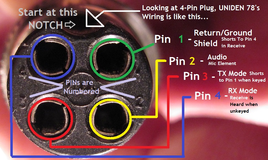
- Pin Identification: Each pin on the 4-pin CB microphone connector serves a specific purpose. The ground pin provides a reference point for electrical signals, the power pin supplies voltage to the microphone, the audio up pin carries the audio signal from the microphone to the radio, and the audio down pin carries the audio signal from the radio to the microphone.
- Color Coding: In many cases, the wires of a 4-pin CB microphone are color-coded to match the pin assignments. This simplifies the wiring process and helps prevent errors. Common color-coding schemes include: white for ground, red for power, blue for audio up, and yellow for audio down.
- Terminal Assignments: The CB radio’s microphone socket also has specific terminal assignments that correspond to the pin assignments on the microphone connector. Matching the pin assignments to the terminal assignments is crucial for proper signal flow and communication.
- Polarity: The polarity of the power and audio connections must be correct. Reversing the polarity can damage the equipment or result in poor audio quality.
Proper pin configuration is essential for establishing a reliable and effective communication channel between the microphone and CB radio. By carefully identifying and matching the pin assignments, users can ensure that the “Color 4 Pin Cb Mic Wiring Diagram” is correctly implemented, leading to clear and intelligible audio transmission and reception.
Wiring Scheme
When considering the “Color 4 Pin Cb Mic Wiring Diagram,” the wiring scheme plays a pivotal role in ensuring the proper functionality and compatibility of the microphone with the CB radio. The wiring scheme dictates the specific arrangement and connection of wires within the microphone cable, matching the pin assignments on the microphone connector to the terminal assignments on the CB radio’s microphone socket.
By adhering to a standard wiring diagram, users can ensure that their 4-pin CB microphone is wired correctly, enabling seamless communication. Deviations from the standard wiring scheme can result in improper signal flow, poor audio quality, or even damage to the equipment. Real-life examples of wiring scheme applications include: connecting a microphone to a handheld CB radio, installing a microphone in a mobile CB radio, or replacing a faulty microphone cable.
Understanding the wiring scheme is crucial for troubleshooting and resolving any issues that may arise with the “Color 4 Pin Cb Mic Wiring Diagram.” By following the standard wiring diagram, users can systematically check the connections, identify any errors or faults, and take appropriate corrective measures. This understanding empowers users to maintain and repair their CB microphone systems effectively.
Color Coding
Within the realm of “Color 4 Pin Cb Mic Wiring Diagram,” color coding plays a vital role in ensuring accurate and efficient wiring. By matching the wire colors to the corresponding pin assignments, users can simplify the wiring process, reduce the risk of errors, and facilitate troubleshooting. This section explores various facets of color coding in the context of 4-pin CB microphone wiring, providing a comprehensive understanding of its significance and practical applications.
- Standardized Color Scheme: The color coding of 4-pin CB microphone wires follows a standardized scheme, typically consisting of white for ground, red for power, blue for audio up, and yellow for audio down. This standardization ensures consistency and ease of identification across different manufacturers and models.
- Simplified Wiring: Color coding simplifies the wiring process by providing a visual cue for matching the wires to the correct pin assignments. This reduces the likelihood of errors, especially for users who are new to CB radio wiring.
- Error Detection: In the event of a wiring error, color coding aids in quick and easy identification. By comparing the wire colors to the pin assignments, users can swiftly locate and correct any discrepancies.
- Compatibility: Color coding promotes compatibility between different 4-pin CB microphones and radios. By adhering to the standardized color scheme, users can ensure that their microphone will work seamlessly with various compatible devices.
Overall, color coding is an integral aspect of “Color 4 Pin Cb Mic Wiring Diagram,” providing a structured approach to wiring and enhancing the overall user experience. By matching the wire colors to the corresponding pin assignments, users can simplify the wiring process, minimize errors, and ensure compatibility, contributing to the effective and reliable operation of their CB radio communication systems.
Soldering Technique
In the context of “Color 4 Pin Cb Mic Wiring Diagram,” soldering technique plays a critical role in ensuring the reliability and longevity of the wired connections. Proper soldering techniques create secure electrical connections between the microphone wires and the CB radio’s microphone socket, enabling uninterrupted signal transmission and clear communication.
Without proper soldering, the connections may become loose or intermittent, resulting in poor audio quality, crackling noises, or complete loss of communication. Moreover, faulty soldering can damage the microphone or CB radio, leading to costly repairs or replacements.
Real-life examples of soldering technique within “Color 4 Pin Cb Mic Wiring Diagram” include:
Soldering the microphone wires to the appropriate terminals on the CB radio’s microphone socket. Soldering the wires of an extension cable to the microphone’s connector. Repairing a broken wire in the microphone cable by soldering the two ends together.
Understanding the importance of proper soldering technique empowers users to create secure and reliable connections in their CB microphone wiring. By following best practices, such as using a high-quality soldering iron, rosin-core solder, and proper flux, users can ensure that their CB microphone wiring diagram functions optimally, delivering clear and consistent communication.
Testing
Within the context of “Color 4 Pin Cb Mic Wiring Diagram,” testing plays a pivotal role in ensuring the proper operation and reliability of the wired connections. By verifying the microphone’s functionality after wiring, users can identify and resolve any potential issues, ensuring clear and uninterrupted communication.
Testing involves checking the microphone’s audio transmission and reception capabilities. This can be done by connecting the microphone to a CB radio and speaking into it, while listening for clear audio output. Alternatively, a multimeter can be used to test the continuity of the microphone’s wires and the electrical connections to the CB radio.
Real-life examples of testing within “Color 4 Pin Cb Mic Wiring Diagram” include:
Testing a newly wired microphone to ensure it is functioning correctly before installing it in a vehicle. Troubleshooting a microphone that is experiencing intermittent audio issues. Verifying the functionality of a microphone after repairing a broken wire.
Understanding the importance of testing empowers users to maintain and troubleshoot their CB microphone wiring, ensuring optimal performance and communication clarity. By incorporating testing into their wiring process, users can proactively identify and resolve any issues, preventing potential communication problems and enhancing the overall user experience.
Troubleshooting
Within the context of “Color 4 Pin Cb Mic Wiring Diagram,” troubleshooting plays a critical role in ensuring the proper functioning and reliability of the wired connections. Troubleshooting involves identifying and resolving any wiring issues that may arise during the installation or usage of the microphone, ensuring clear and uninterrupted communication.
Troubleshooting is a crucial component of “Color 4 Pin Cb Mic Wiring Diagram” because it enables users to proactively identify and address any potential problems with the microphone’s wiring. By understanding the cause-and-effect relationship between different wiring issues and their symptoms, users can effectively troubleshoot and resolve common problems, such as intermittent audio, lack of audio, or distorted audio.
Real-life examples of troubleshooting within “Color 4 Pin Cb Mic Wiring Diagram” include:
Identifying a loose connection between the microphone and the CB radio, resulting in intermittent audio. Troubleshooting a broken wire in the microphone cable, causing a complete loss of audio. Resolving a grounding issue that introduces noise into the audio signal.
Understanding the practical applications of troubleshooting empowers users to maintain and troubleshoot their CB microphone wiring effectively. By incorporating troubleshooting into their wiring process, users can proactively identify and resolve any issues, preventing potential communication problems and enhancing the overall user experience.
Interoperability
Within the context of “Color 4 Pin Cb Mic Wiring Diagram,” interoperability plays a pivotal role in ensuring seamless communication among different CB radios, regardless of their make, model, or manufacturer. By adhering to standardized wiring configurations and pin assignments, users can connect their microphones to various CB radios without compatibility issues, facilitating effective audio transmission and reception.
- Universal Compatibility: The standardized wiring diagram enables microphones to be used with different CB radios, promoting interoperability and ease of use.
- Simplified Installation: By following the standard wiring scheme, users can easily install microphones in different CB radios, reducing the need for complex modifications or adaptations.
- Enhanced Communication: Interoperability allows users to communicate seamlessly with others using different CB radios, expanding the reach and effectiveness of communication.
- Cost-Effective Solution: By eliminating the need for proprietary microphones or adapters, interoperability helps users save costs and simplifies their CB radio setups.
In summary, interoperability serves as a cornerstone of “Color 4 Pin Cb Mic Wiring Diagram,” enabling users to connect their microphones to different CB radios seamlessly. It promotes universal compatibility, simplifies installation, enhances communication, and offers a cost-effective solution, ultimately contributing to a more efficient and enjoyable CB radio experience.


![[DIAGRAM] 4 Pin Microphone Wiring Diagrams](https://lh5.googleusercontent.com/proxy/JkFU5wn_uIlK3xkzgwbMExfphYXC51MCzptUOKM3vTUg8qo0DaI_qxL4iKdeIdBjYh51GzTaI9DOdqQh-KbK4XLieSKN8dYUVbQn_q6oUlNW7DrWSvzHnX0HWfYkDILKy_U0oyqAgvLQtwTlCi1KcyMx749dsqeR0-xrHS23Xej1UjPxIkTXWyVlkNGfTP9FZEtKYTyE2-auLgLHW0bc05OufrhJDzL6WQ3R0p0Nb5FOZy-G0ELlm7UHumLVIt5_BfPC8B7Ob6cNkVndNjq8Rw9WcQGgZA=s0-d)


Related Posts


