Cole Hersee Solenoid Wiring Diagram visually depicts the electrical connections required to operate a Cole Hersee solenoid, an electromagnetic device that converts electrical energy into mechanical motion. It illustrates the proper wiring of the solenoid’s coil to a power source and control switch, ensuring its efficient operation and preventing damage.
Solenoid wiring diagrams are crucial for safe and precise solenoid installation, particularly in industrial and automotive applications. They guide technicians in connecting the solenoid to various components such as batteries, switches, and control systems. Proper wiring ensures that the solenoid operates as intended, delivering the desired mechanical action.
Historically, solenoid wiring diagrams were drawn manually on paper. Today, sophisticated software tools are available that assist in creating accurate and detailed diagrams, eliminating the potential for errors. This technological advancement has contributed to the widespread adoption of solenoids in various industries.
Understanding the essential aspects of “Cole Hersee Solenoid Wiring Diagram” is crucial for effectively conveying information about this topic. As a noun phrase, it encompasses various dimensions that contribute to its significance. Here are ten key aspects to consider:
- Electrical Wiring: Explains the electrical connections and circuits involved in the wiring diagram.
- Solenoid Function: Describes the operation and purpose of a solenoid in converting electrical energy to mechanical motion.
- Circuit Protection: Discusses the safety measures and components used to protect the solenoid and its connected circuitry.
- Wire Gauge and Type: Explores the selection and specifications of electrical wires based on current requirements and application.
- Connector Types: Explains the different types of electrical connectors used to establish secure and reliable connections.
- Testing and Troubleshooting: Covers the methods for testing the solenoid and wiring diagram to ensure proper functionality.
- Industry Standards and Regulations: Highlights the adherence to established guidelines and codes for safe and compliant installations.
- Environmental Considerations: Discusses the impact of environmental factors on the wiring diagram and solenoid operation.
- Maintenance and Inspection: Explains the importance of regular maintenance and inspection to ensure optimal performance and prevent failures.
- Real-World Applications: Provides examples of how Cole Hersee solenoid wiring diagrams are used in various industries and applications.
These key aspects provide a comprehensive understanding of Cole Hersee solenoid wiring diagrams, enabling effective communication and knowledge transfer about this topic. They serve as the building blocks for further exploration of the subject matter.
Electrical Wiring
Delving into the aspect of “Electrical Wiring” is crucial for comprehending the intricacies of “Cole Hersee Solenoid Wiring Diagram.” Electrical wiring forms the backbone of the solenoid’s functionality, enabling the flow of electrical current to generate the necessary magnetic field for mechanical actuation.
- Circuit Components: Solenoid wiring diagrams illustrate the electrical components involved, such as switches, relays, diodes, and resistors. These components work in conjunction to control the flow of current through the solenoid coil, ensuring proper operation.
- Wire Selection: The choice of electrical wire is critical, as it must be able to handle the current draw of the solenoid while minimizing voltage drop. Wiring diagrams specify the appropriate wire gauge and insulation type based on the solenoid’s specifications.
- Circuit Protection: Solenoid wiring diagrams incorporate protective measures such as fuses or circuit breakers to safeguard the circuit from overcurrent conditions. These devices prevent damage to the solenoid and other electrical components.
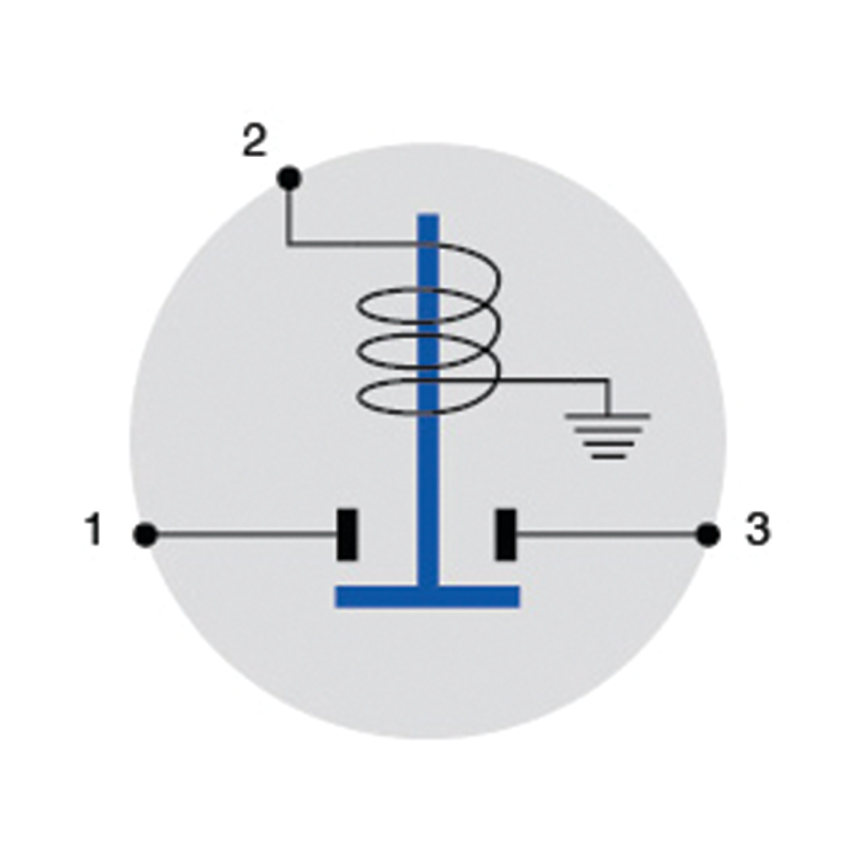
- Grounding: Proper grounding is essential for electrical safety and noise reduction. Wiring diagrams indicate the grounding points to ensure the solenoid is correctly connected to the system ground.
Understanding the electrical wiring aspect of Cole Hersee solenoid wiring diagrams empowers technicians and engineers to design, install, and maintain solenoid-based systems effectively. It ensures the safe and reliable operation of solenoids in various applications, ranging from industrial machinery to automotive systems.
Solenoid Function
Within the context of “Cole Hersee Solenoid Wiring Diagram,” understanding solenoid function is paramount. Solenoids are electromechanical devices that convert electrical energy into mechanical motion, playing a critical role in various industrial and automotive applications. This aspect delves into the inner workings of solenoids, exploring their operation and purpose.
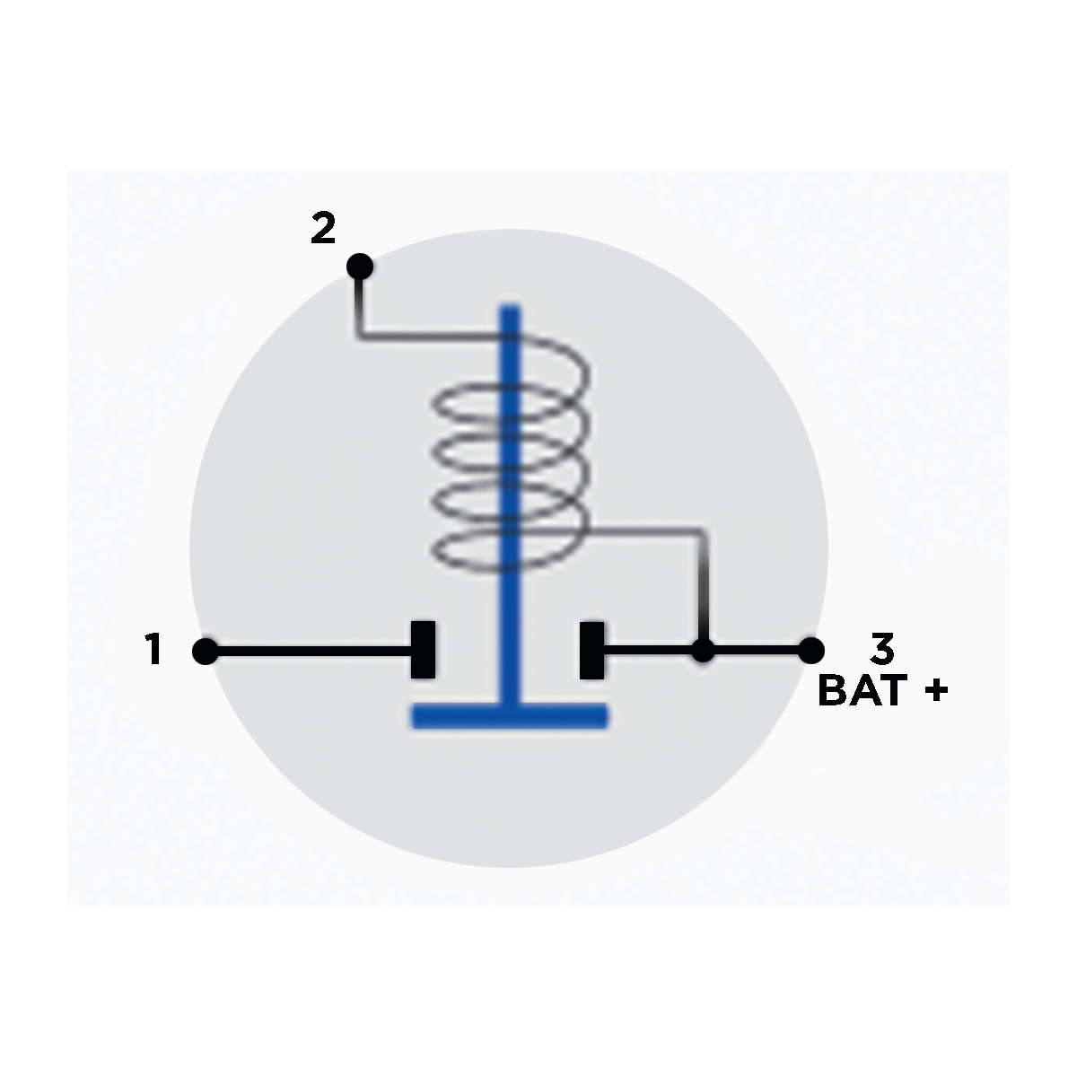
- Electromagnetic Coil: The solenoid comprises an electromagnetic coil, typically made of copper wire wound around a cylindrical or tubular core. When an electric current flows through the coil, it generates a magnetic field.
- Movable Plunger: Inside the coil, a movable plunger made of ferromagnetic material is positioned. When the coil is energized, the magnetic field attracts the plunger, causing it to move linearly or rotate.
- Spring Mechanism: Often, solenoids incorporate a spring mechanism that returns the plunger to its original position when the electrical current is turned off.
- Applications: Solenoids find widespread use in controlling valves, switches, actuators, and other mechanical devices. They are commonly found in automotive starter motors, fuel injection systems, and industrial automation.
Understanding solenoid function is essential for interpreting “Cole Hersee Solenoid Wiring Diagrams.” These diagrams illustrate the electrical connections necessary to activate the solenoid coil, enabling the conversion of electrical energy into mechanical motion. Proper wiring ensures that the solenoid operates as intended, delivering the desired mechanical action.
Circuit Protection
Within the context of “Cole Hersee Solenoid Wiring Diagram,” circuit protection holds paramount importance in ensuring the safe and reliable operation of the solenoid and its associated circuitry. Solenoids, being electromagnetic devices, generate magnetic fields and draw significant electrical current, necessitating protective measures to prevent damage and potential hazards.
- Fuses: Fuses are sacrificial devices designed to interrupt the circuit in the event of excessive current flow. They are placed in series with the solenoid coil and blow when the current exceeds a predetermined threshold, preventing damage to the solenoid and other components.
- Circuit Breakers: Circuit breakers are reusable protective devices that automatically trip and interrupt the circuit when the current exceeds safe limits. They can be reset manually once the fault is cleared, providing convenience and cost-effectiveness compared to fuses.
- Surge Protectors: Surge protectors safeguard the solenoid and circuitry from voltage spikes and transients that can occur during switching or lightning strikes. They divert these harmful surges to ground, protecting sensitive electronic components from damage.
- Grounding: Proper grounding provides a low-resistance path for stray currents and fault currents to safely dissipate into the earth. It helps prevent electrical shocks, equipment damage, and electromagnetic interference.
Understanding and implementing circuit protection measures are crucial when working with “Cole Hersee Solenoid Wiring Diagrams.” These protective components ensure the safe and reliable operation of solenoids in various applications, ranging from industrial machinery to automotive systems.
Wire Gauge and Type
In the context of “Cole Hersee Solenoid Wiring Diagram,” selecting the appropriate wire gauge and type is crucial for ensuring safe and efficient operation of the solenoid. Electrical wires serve as the pathways for current flow, and their characteristics directly impact the performance and reliability of the solenoid system.
- Current Carrying Capacity: The wire gauge, which refers to the cross-sectional area of the wire, determines its current carrying capacity. Solenoid wiring diagrams specify the minimum wire gauge required to handle the solenoid’s current draw under normal operating conditions.
- Voltage Drop: The wire type, typically copper or aluminum, influences the voltage drop along the wire. Longer wires or those with smaller gauges experience greater voltage drop, which can affect the solenoid’s performance. Wiring diagrams account for voltage drop and specify the appropriate wire type to minimize power loss.
- Insulation: The wire’s insulation protects against electrical shocks and short circuits. Solenoid wiring diagrams indicate the insulation type and thickness required to withstand the voltage and environmental conditions of the application.
- Flexibility: In certain applications, flexibility is a key consideration. Wiring diagrams may recommend flexible wires to accommodate movement or tight spaces.
Understanding and adhering to the wire gauge and type specifications provided in “Cole Hersee Solenoid Wiring Diagrams” helps prevent overheating, voltage drop issues, and potential safety hazards. Proper wire selection ensures that the solenoid receives the necessary electrical power to operate reliably and efficiently.
Connector Types
Within the context of “Cole Hersee Solenoid Wiring Diagram,” the selection and use of appropriate connector types are paramount for ensuring reliable and secure electrical connections. Connectors provide the means to join wires, cables, and components, establishing a continuous electrical pathway while maintaining signal integrity and preventing short circuits.
- Screw Terminals: Screw terminals are a common type of connector found in solenoid wiring diagrams. They consist of a screw that tightens down on the wire, creating a secure mechanical and electrical connection. Screw terminals are easy to install and maintain, making them suitable for various applications.
- Crimp Connectors: Crimp connectors are another widely used type of connector. They involve crimping a metal sleeve around the wire using a specialized tool. Crimp connectors provide a gas-tight connection that resists vibration and corrosion, making them ideal for harsh environments.
- Push-In Connectors: Push-in connectors offer a convenient and time-saving method of connecting wires. They feature a spring-loaded mechanism that allows wires to be simply pushed into the connector body, creating a secure and reliable connection without the need for tools.
- PCB Connectors: PCB connectors are designed for printed circuit boards (PCBs). They come in various -, including headers, sockets, and edge connectors. PCB connectors provide a reliable and efficient means of interfacing solenoids with PCBs, ensuring proper signal transmission and power distribution.
Understanding and selecting the appropriate connector types based on the solenoid’s requirements, environmental conditions, and application demands are crucial. Proper connector selection and installation help prevent loose connections, voltage drops, and potential safety hazards, ensuring the reliable operation of solenoids in various industrial and automotive applications.
Testing and Troubleshooting
In the realm of “Cole Hersee Solenoid Wiring Diagram,” testing and troubleshooting play a critical role in ensuring the solenoid’s proper operation and preventing costly downtime. Testing involves applying electrical signals to the solenoid and measuring its response to verify its functionality. Troubleshooting, on the other hand, entails identifying and rectifying any faults within the solenoid or its wiring diagram.
Testing methods encompass continuity checks to verify complete circuits, resistance measurements to assess coil integrity, and voltage checks to confirm proper power supply. Troubleshooting techniques include examining wiring connections for looseness, checking for damaged or frayed wires, and utilizing diagnostic tools such as multimeters and oscilloscopes to pinpoint faults.
For instance, in an automotive application, a faulty solenoid in the starter motor can prevent the engine from cranking. Troubleshooting involves testing the solenoid’s electrical connections, checking for loose or damaged wires, and measuring the voltage supplied to the solenoid. By identifying and resolving the issue, the solenoid and starter motor can be restored to proper working order.
The practical significance of testing and troubleshooting lies in ensuring reliable solenoid operation, preventing equipment damage, and minimizing downtime. Regular testing and maintenance can identify potential issues early on, allowing for timely repairs and preventing catastrophic failures.
Industry Standards and Regulations
Within the context of “Cole Hersee Solenoid Wiring Diagram,” industry standards and regulations play a crucial role in ensuring the safety, reliability, and compliance of solenoid installations. These established guidelines and codes provide a framework for proper design, installation, and maintenance practices, minimizing risks and ensuring optimal performance.
- National Electrical Code (NEC): The NEC is a widely adopted set of regulations in the United States that governs the installation and maintenance of electrical systems, including those involving solenoids. It outlines specific requirements for wire sizing, overcurrent protection, grounding, and other safety measures to prevent electrical fires, shocks, and other hazards.
- Underwriters Laboratories (UL): UL is an independent safety certification organization that develops and publishes standards for various electrical components, including solenoids. UL standards address aspects such as material composition, construction, performance testing, and safety features, ensuring that solenoids meet stringent quality and safety requirements.
- International Electrotechnical Commission (IEC): The IEC is a global organization that develops international standards for electrical and electronic technologies. Its standards for solenoids cover areas such as terminology, testing methods, and performance specifications, facilitating international trade and ensuring a consistent level of quality and safety.
- Industry-Specific Regulations: In addition to general electrical codes and standards, specific industries may have their own regulations governing the use of solenoids. For instance, the automotive industry has standards for solenoid applications in vehicles, addressing factors such as durability, vibration resistance, and electromagnetic compatibility.
Adhering to industry standards and regulations in “Cole Hersee Solenoid Wiring Diagram” is paramount for several reasons. It ensures compliance with legal requirements, minimizes safety risks, enhances system reliability, and facilitates troubleshooting and maintenance. By following established guidelines, engineers and technicians can design and install solenoid-based systems that meet the highest levels of safety, performance, and longevity.
Environmental Considerations
Within the context of “Cole Hersee Solenoid Wiring Diagram,” environmental considerations play a critical role in ensuring the reliable and safe operation of solenoids. Various environmental factors can affect the wiring diagram and solenoid performance, necessitating careful design and installation practices.
- Temperature Extremes: Solenoids and their wiring are susceptible to extreme temperatures. Excessive heat can lead to insulation breakdown, wire damage, and premature solenoid failure. Conversely, extreme cold can stiffen wires, making them more prone to breakage, and hinder solenoid actuation.
- Moisture and Corrosion: Exposure to moisture and corrosive substances can damage electrical connections and solenoid components. Moisture can cause short circuits, while corrosion can increase resistance and lead to solenoid malfunction. Proper sealing and protective measures are crucial in harsh environments.
- Vibration and Shock: Solenoids are often subjected to vibration and shock in industrial and automotive applications. These forces can loosen connections, damage wires, and cause solenoid misalignment. Robust wiring practices, shock-absorbing mounts, and vibration-resistant solenoids are essential to mitigate these effects.
- Electromagnetic Interference (EMI): Solenoids can be sources or victims of EMI, which can disrupt solenoid operation and cause erratic behavior. Proper shielding, grounding, and cable routing techniques are necessary to minimize EMI and ensure reliable solenoid performance.
Understanding and addressing environmental considerations in “Cole Hersee Solenoid Wiring Diagram” is vital for designing and installing solenoid-based systems that can withstand harsh conditions, operate reliably, and meet safety standards. By taking environmental factors into account, engineers and technicians can create robust and durable solenoid systems that perform as intended in real-world applications.
Maintenance and Inspection
In the context of “Cole Hersee Solenoid Wiring Diagram,” maintenance and inspection are crucial aspects that contribute to the long-term reliability and effectiveness of solenoid-based systems. Regular maintenance and inspection practices help identify potential issues early on, enabling timely repairs and preventing catastrophic failures that could lead to costly downtime or safety hazards.
Maintenance tasks may include periodic cleaning of solenoid components to remove dirt, dust, and debris that can interfere with proper operation. Inspection involves visually examining the solenoid, wiring, and connections for signs of wear, damage, or corrosion. By adhering to a regular maintenance and inspection schedule, potential problems can be detected and addressed before they escalate into major issues.
For instance, in an industrial setting, solenoids used in automated machinery require regular maintenance to ensure uninterrupted operation. Failure to perform maintenance can lead to solenoid malfunctions, causing production delays and potential safety risks. Regular inspection and cleaning can identify worn-out components or loose connections, allowing for timely replacement or tightening, preventing sudden failures and maintaining optimal performance.
Understanding the importance of maintenance and inspection is essential for developing effective maintenance strategies for solenoid-based systems. By incorporating these practices into the “Cole Hersee Solenoid Wiring Diagram,” engineers and technicians can design and implement systems that are reliable, safe, and operate at peak efficiency throughout their lifespan.
Real-World Applications
Within the context of “Cole Hersee Solenoid Wiring Diagram,” real-world applications serve as a critical component, showcasing the practical implementation and benefits of solenoid wiring diagrams in diverse industries and applications. These examples illustrate how the technical aspects of solenoid wiring diagrams translate into tangible solutions for real-world problems.
For instance, in the automotive industry, Cole Hersee solenoid wiring diagrams are essential for designing and installing electrical systems in vehicles. Solenoids are used in various automotive applications, such as starter motors, fuel injection systems, and transmission control. The wiring diagrams provide clear instructions on how to connect solenoids to other electrical components, ensuring proper functionality and preventing electrical faults.
Another example is in industrial automation, where solenoids are widely employed in controlling valves, actuators, and other mechanical devices. Cole Hersee solenoid wiring diagrams guide engineers and technicians in designing and installing solenoid-based systems for automated machinery, assembly lines, and robotics. Proper wiring is crucial for ensuring reliable operation, preventing downtime, and enhancing overall efficiency.
Understanding real-world applications of Cole Hersee solenoid wiring diagrams is essential for comprehending their practical significance. These examples demonstrate how solenoid wiring diagrams are used to design and implement electrical systems that control various mechanical functions in a wide range of industries, from automotive to industrial automation. By incorporating real-world applications into the “Cole Hersee Solenoid Wiring Diagram,” readers gain valuable insights into the practical aspects of solenoid technology and its applications in solving real-world challenges.
![[DIAGRAM] Cole Hersee Solenoid Wiring Diagram](https://i0.wp.com/acdcmarineinc.com/wp-content/uploads/2016/02/cole-hersee-smart-isoaltor-800x800.jpg?resize=665%2C665&ssl=1)


Related Posts


