A coil-to-distributor wiring diagram provides a schematic representation of the electrical connections between an ignition coil and a distributor in an internal combustion engine. It illustrates the flow of high-voltage electricity from the coil to the distributor, which then distributes the current to the spark plugs.
Wiring diagrams are crucial for understanding the operation and troubleshooting of ignition systems. They enable technicians to identify and correct electrical faults, ensuring optimal engine performance. The specific wiring pattern varies depending on the vehicle model and ignition system design.
In the context of automotive repair, these diagrams are essential for diagnosing and resolving ignition problems. Historically, the development of electronic ignition systems has reduced the complexity of wiring diagrams, but they remain indispensable tools for understanding and maintaining ignition systems.
Coil-to-distributor wiring diagrams are essential for understanding and troubleshooting ignition systems in internal combustion engines. They provide a schematic representation of the electrical connections between the ignition coil and the distributor, which is crucial for ensuring optimal engine performance.
- Components: Wiring diagrams identify the specific components involved in the ignition system, including the ignition coil, distributor, spark plugs, and associated wiring.
- Connections: Diagrams illustrate the electrical connections between these components, showing how current flows from the coil to the distributor and then to the spark plugs.
- Voltage and Current: Wiring diagrams indicate the voltage and current requirements for the ignition system, ensuring that the proper components are used and that the system operates within specified parameters.
- Troubleshooting: Diagrams aid in troubleshooting ignition problems by providing a visual representation of the system, helping technicians locate faults and identify potential issues.
- Maintenance: Wiring diagrams are essential for performing maintenance on ignition systems, as they provide instructions on how to disconnect, reconnect, and replace components.
- Engine Performance: A properly wired ignition system ensures optimal engine performance by delivering the correct spark to the spark plugs at the appropriate time.
- Safety: Wiring diagrams help ensure the safe operation of ignition systems by providing guidelines for proper installation and maintenance, minimizing the risk of electrical hazards.
- Compatibility: Diagrams are specific to particular vehicle models and ignition system configurations, ensuring that the wiring is compatible with the engine and its electronic components.
In conclusion, coil-to-distributor wiring diagrams are vital for understanding, troubleshooting, maintaining, and ensuring the safe operation of ignition systems. They provide detailed information on components, connections, voltage and current requirements, troubleshooting procedures, and compatibility, enabling technicians and enthusiasts to work effectively on these systems.
Components
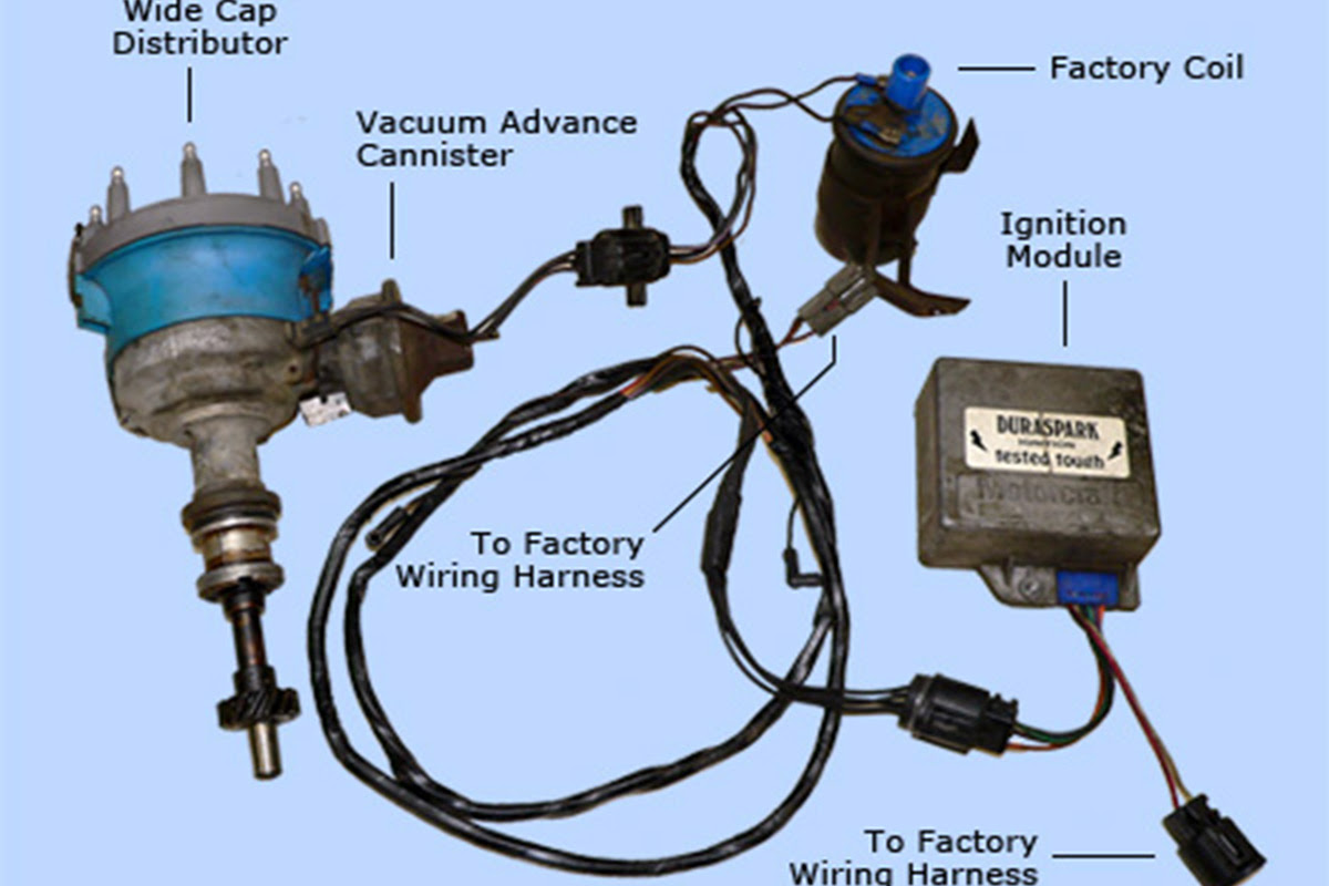
In a coil-to-distributor ignition system, the wiring diagram serves as a blueprint, detailing the connections between the ignition coil and the distributor, as well as the associated components: spark plugs and wiring. Understanding these components and their interconnections is crucial for diagnosing and resolving ignition problems.
The ignition coil is responsible for generating the high voltage required to create a spark at the spark plugs. The distributor then distributes this high voltage to the appropriate spark plug based on the engine’s firing order, ensuring that the spark occurs at the correct time in each cylinder.
Real-life examples of the practical application of coil-to-distributor wiring diagrams include:
- Troubleshooting ignition misfires by identifying faulty connections or components within the ignition system.
- Performing maintenance on the ignition system, such as replacing spark plugs or the distributor cap, by following the wiring diagram to ensure proper component installation.
- Upgrading or modifying the ignition system, such as installing a performance ignition coil or an electronic distributor, by referencing the wiring diagram for compatibility and proper installation.
By understanding the components and connections outlined in a coil-to-distributor wiring diagram, technicians and enthusiasts can effectively diagnose, maintain, and modify ignition systems, ensuring optimal engine performance and reliability.
Connections
Within the context of a coil-to-distributor wiring diagram, the connections between components play a critical role in ensuring the proper functioning of the ignition system. These diagrams illustrate how current flows from the ignition coil, through the distributor, and ultimately to the spark plugs, providing a visual representation of the electrical pathways involved.
Understanding these connections is essential for troubleshooting and diagnosing ignition problems. By tracing the flow of current through the wiring diagram, technicians can identify potential points of failure or incorrect connections that may be causing ignition misfires or other performance issues.
Real-life examples of the practical significance of understanding these connections include:
- Identifying a faulty connection between the ignition coil and the distributor, which can cause intermittent spark or engine stalling.
- Diagnosing a problem with the distributor cap or rotor, which can disrupt the proper distribution of current to the spark plugs.
- Troubleshooting a short circuit in the spark plug wires, which can prevent the spark plugs from receiving the necessary voltage to generate a spark.
By comprehending the connections and current flow depicted in a coil-to-distributor wiring diagram, technicians and enthusiasts can effectively maintain and repair ignition systems, ensuring optimal engine performance and reliability.
Voltage and Current
Within the context of a coil-to-distributor wiring diagram, voltage and current play critical roles in ensuring the proper functioning of the ignition system. These diagrams specify the voltage and current requirements for each component, ensuring that the ignition coil, distributor, and spark plugs operate within their optimal parameters.
Understanding the voltage and current requirements is essential for selecting the appropriate components and ensuring compatibility within the ignition system. For instance, using an ignition coil with insufficient voltage output can result in weak spark or ignition failure, while an oversized coil can damage sensitive electronic components.
Real-life examples of the practical significance of voltage and current in coil-to-distributor wiring diagrams include:
- Selecting the correct spark plugs based on their voltage requirements, ensuring optimal spark generation and engine performance.
- Upgrading the ignition system with a high-performance ignition coil to increase spark energy and improve engine efficiency.
- Troubleshooting ignition problems by measuring voltage and current at various points in the system to identify potential faults.
By comprehending the voltage and current requirements specified in coil-to-distributor wiring diagrams, technicians and enthusiasts can effectively design, maintain, and troubleshoot ignition systems, ensuring optimal engine performance and reliability.
In summary, voltage and current are critical components of coil-to-distributor wiring diagrams, providing essential information for selecting compatible components and ensuring the proper operation of the ignition system. Understanding these requirements enables effective troubleshooting, maintenance, and performance optimization of internal combustion engines.
Troubleshooting
Within the context of coil-to-distributor ignition systems, troubleshooting and diagnosing faults heavily rely on wiring diagrams. These diagrams provide a comprehensive visual representation of the system, enabling technicians to trace electrical connections, identify faulty components, and understand the flow of current.
Consider this real-life example: A vehicle experiences intermittent engine misfires. By referring to the coil-to-distributor wiring diagram, a technician can systematically troubleshoot the system. Starting from the ignition coil, they can check the voltage and continuity of the connections to the distributor and then proceed to inspect the distributor cap, rotor, and spark plug wires. This methodical approach, guided by the wiring diagram, helps isolate the faulty component and identify the root cause of the misfires.
The practical applications of understanding wiring diagrams extend beyond troubleshooting. They also play a vital role in maintenance and performance optimization. For instance, when upgrading an ignition system with a high-performance ignition coil, the wiring diagram ensures proper compatibility and installation. Additionally, during routine maintenance, such as replacing spark plugs or the distributor cap, the diagram serves as a reference for correct component selection and wiring.
In summary, troubleshooting, maintenance, and performance optimization of coil-to-distributor ignition systems heavily depend on wiring diagrams. These diagrams provide a visual representation of the system, enabling technicians to locate faults, select compatible components, and optimize performance. Understanding wiring diagrams is a critical aspect of automotive repair and maintenance, ensuring the reliability and efficiency of internal combustion engines.
Maintenance
In the context of coil-to-distributor ignition systems, maintenance and repair heavily rely on wiring diagrams. These diagrams are critical components of any maintenance procedure, providing step-by-step instructions on how to safely and effectively disconnect, reconnect, and replace various components within the ignition system.
Consider a common maintenance task: replacing the distributor cap. Without a wiring diagram, a technician might struggle to identify the correct wires and their connection points. By referring to the diagram, they can quickly and accurately locate the wires, ensuring proper reinstallation and avoiding any potential damage to the system.
Another example of the practical significance of wiring diagrams in maintenance is troubleshooting ignition problems. When an ignition system malfunctions, the wiring diagram serves as a roadmap, guiding technicians through the process of isolating the faulty component. By systematically checking connections and components based on the diagram, they can pinpoint the root cause of the problem and perform the necessary repairs.
In summary, maintenance and repair of coil-to-distributor ignition systems are heavily dependent on wiring diagrams. These diagrams provide clear instructions for disconnecting, reconnecting, and replacing components, enabling technicians to perform maintenance tasks efficiently and accurately. Understanding wiring diagrams is essential for ensuring the reliability and performance of internal combustion engines.
Engine Performance
Within the context of internal combustion engines, the coil-to-distributor wiring diagram plays a critical role in ensuring optimal engine performance. The wiring diagram provides a detailed schematic of the electrical connections between the ignition coil and the distributor, which are responsible for delivering the correct spark to the spark plugs at the appropriate time during the engine cycle.
A properly wired ignition system is essential for optimal engine performance because it ensures that the spark plugs receive the necessary voltage and current to generate a strong and timely spark. This spark ignites the air-fuel mixture in the engine’s cylinders, leading to efficient combustion and power generation.
Real-life examples of the significance of a properly wired ignition system in engine performance include:
- Improved engine starting, especially in cold or humid conditions, due to a stronger and more reliable spark.
- Smoother engine idling and reduced engine knocking or detonation, resulting from precise spark timing and consistent combustion.
- Increased fuel efficiency and reduced emissions, as a properly timed spark ensures complete combustion of the air-fuel mixture.
Understanding the connection between a coil-to-distributor wiring diagram and engine performance enables technicians and enthusiasts to diagnose and resolve ignition problems, optimize ignition timing, and ultimately improve the overall performance and efficiency of internal combustion engines.
Safety
Wiring diagrams are essential for the safe operation of coil-to-distributor ignition systems, providing clear instructions and guidelines for proper installation and maintenance. By adhering to these guidelines, technicians and enthusiasts can minimize the risk of electrical hazards, ensuring the safety of both individuals and the ignition system itself.
- Electrical Short Circuits: Wiring diagrams help prevent electrical short circuits by providing a clear roadmap for wiring connections. Following the diagram ensures that wires are routed correctly, preventing accidental contact and potential short circuits that could lead to fires or damage to the ignition system.
- Overheating and Damage: Proper wiring ensures that the ignition coil and distributor operate within their specified temperature ranges. Wiring diagrams provide guidance on wire gauge, insulation, and connection methods, preventing overheating and damage to components due to excessive current or voltage.
- Grounding and Shielding: Wiring diagrams specify proper grounding and shielding techniques, which are crucial for minimizing electromagnetic interference (EMI) and ensuring stable ignition system operation. Grounding provides a low-resistance path for electrical current to flow, preventing voltage spikes and EMI, while shielding protects sensitive components from external electrical noise.
- Compatibility and Safety Features: Wiring diagrams ensure compatibility between different ignition system components, such as the ignition coil, distributor, and spark plugs. They also incorporate safety features, such as fuse placement and wire color-coding, to facilitate troubleshooting and prevent incorrect connections.
In summary, wiring diagrams play a vital role in the safe operation of coil-to-distributor ignition systems. By providing guidelines for proper installation and maintenance, they minimize the risk of electrical hazards, ensuring the safety and reliability of the ignition system and the overall performance of the engine.
Compatibility
Within the context of “Coil To Distributor Wiring Diagram”, compatibility plays a crucial role in ensuring the proper functioning and performance of the ignition system. Wiring diagrams are specific to particular vehicle models and ignition system configurations, guaranteeing that the electrical connections and components are compatible with the engine and its electronic components.
- Engine Specifications: Diagrams account for the specific engine specifications, such as the number of cylinders, firing order, and ignition timing requirements. This ensures that the ignition system operates in sync with the engine’s mechanical components.
- Electronic Components: Wiring diagrams consider the compatibility of the ignition coil, distributor, and other electronic components. They specify the correct voltage, current, and resistance values to prevent damage to sensitive components and ensure optimal performance.
- Vehicle-Specific Features: Diagrams incorporate vehicle-specific features, such as immobilizer systems, anti-theft devices, and engine management systems. This ensures that the ignition system integrates seamlessly with the vehicle’s electronic architecture.
- Real-Life Implications: Using a compatible wiring diagram is crucial to avoid ignition problems, engine damage, and potential safety hazards. Incorrect wiring can lead to misfires, poor engine performance, and even electrical fires.
In conclusion, compatibility is a critical aspect of coil-to-distributor wiring diagrams. By ensuring compatibility with the specific vehicle model and ignition system configuration, these diagrams facilitate the proper installation, operation, and maintenance of the ignition system, contributing to the overall performance, reliability, and safety of the engine.


Related Posts


