A Chevy Turn Signal Switch Wiring Diagram provides a visual representation of the electrical connections associated with the turn signal switch in a Chevrolet vehicle. It illustrates the specific sequence and location of wires, connectors, and other components involved in the operation of the turn signals, including both the left and right indicators.
Understanding this wiring diagram is crucial for various reasons. Primarily, it ensures safe and proper functioning of the turn signals, enabling the driver to effectively communicate their intended direction to other vehicles on the road. Furthermore, it assists mechanics and auto enthusiasts in troubleshooting any electrical issues related to the turn signal system.
Reflecting on the historical development of automobiles, the introduction of turn signals represents a significant advancement in driving safety. The ability to clearly indicate the vehicle’s intended direction has reduced accidents and enhanced overall traffic flow.
The key aspects of a Chevy Turn Signal Switch Wiring Diagram are indispensable for comprehending the electrical connections and functionality of the turn signal system in a Chevrolet vehicle. These aspects provide a comprehensive understanding of the various components and their interrelationships, enabling effective troubleshooting and maintenance.
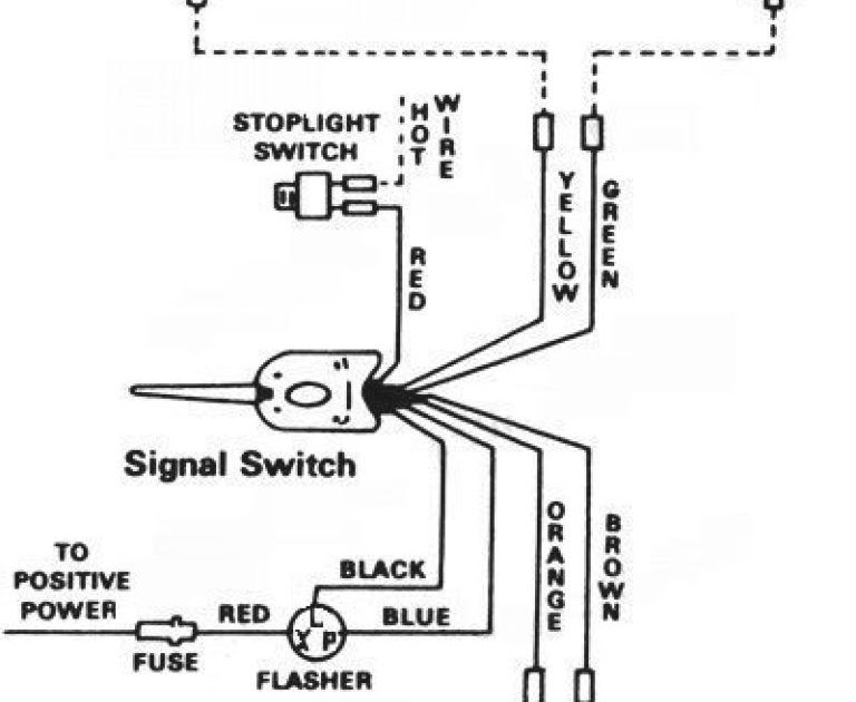
- Circuitry: The diagram illustrates the electrical pathways and connections associated with the turn signal switch, including the power source, ground, and signal wires.
- Components: It identifies the specific components involved in the turn signal system, such as the switch itself, flasher relay, and turn signal bulbs.
- Color-coding: The diagram utilizes color-coding to differentiate between wires, making it easier to trace and identify connections.
- Connector types: It specifies the types of electrical connectors used in the system, such as spade connectors, bullet connectors, or pigtails.
- Switch operation: The diagram explains the mechanical operation of the turn signal switch, including the positions for left, right, and hazard signals.
- Flasher relay: It illustrates the role of the flasher relay in generating the intermittent flashing of the turn signals.
- Troubleshooting: The diagram serves as a valuable guide for troubleshooting electrical issues related to the turn signal system.
- Compatibility: It indicates the specific Chevrolet models and years to which the wiring diagram applies.
These aspects collectively provide a comprehensive understanding of the Chevy Turn Signal Switch Wiring Diagram, enabling mechanics, auto enthusiasts, and vehicle owners to diagnose and resolve electrical issues effectively, ensuring the proper functioning of turn signals for enhanced driving safety.
Circuitry
Circuitry forms the backbone of any electrical system, including the turn signal system in a Chevrolet vehicle. The Chevy Turn Signal Switch Wiring Diagram meticulously outlines these electrical pathways, enabling a comprehensive understanding of how power flows through the system and how the turn signals operate.
Without a clear understanding of the circuitry, troubleshooting electrical issues related to the turn signal system would be extremely challenging. The diagram provides a visual representation of the connections between the turn signal switch, flasher relay, turn signal bulbs, and other components, allowing mechanics and auto enthusiasts to trace and identify faults efficiently.
For instance, if the left turn signal is not functioning, the diagram guides the inspection of the power source, ground connection, and signal wire associated with the left turn signal circuit. This systematic approach to troubleshooting ensures a targeted diagnosis and repair, preventing unnecessary part replacements and saving time and resources.
Furthermore, the circuitry aspect of the Chevy Turn Signal Switch Wiring Diagram plays a crucial role in understanding the behavior and functionality of the turn signal system. The diagram explains how the switch controls the flow of current to the left or right turn signal circuit, activating the corresponding bulbs.
In summary, the circuitry aspect of the Chevy Turn Signal Switch Wiring Diagram is a critical component for comprehending the electrical connections and operation of the turn signal system. It empowers mechanics and vehicle owners to diagnose and resolve electrical issues effectively, ensuring the proper functioning of turn signals for enhanced driving safety.
Components
The Chevy Turn Signal Switch Wiring Diagram plays a pivotal role in identifying and understanding the various components that constitute the turn signal system in Chevrolet vehicles. These components work in unison to ensure the proper functioning of turn signals, a crucial safety feature for effective communication on the road.
- Turn Signal Switch: The heart of the turn signal system, this switch controls the activation and deactivation of turn signals. It typically includes a lever or stalk that the driver moves to indicate the intended direction.
- Flasher Relay: This electronic device regulates the blinking pattern of the turn signals. It generates intermittent electrical pulses that cause the turn signal bulbs to flash at a specific rate.
- Turn Signal Bulbs: Positioned in the front and rear of the vehicle, these bulbs illuminate when the turn signals are activated, providing visual indication of the intended direction.
- Electrical Connectors: Various electrical connectors, such as spade connectors and bullet connectors, are utilized to establish secure electrical connections between the turn signal switch, flasher relay, turn signal bulbs, and wiring harness.
Understanding the components of the turn signal system through the Chevy Turn Signal Switch Wiring Diagram is essential for troubleshooting and maintenance purposes. By identifying faulty components or loose connections, mechanics and vehicle owners can efficiently restore the proper functioning of the turn signals, ensuring safety on the road.
Color-coding
Within the comprehensive Chevy Turn Signal Switch Wiring Diagram, color-coding plays a crucial role in simplifying the identification and tracing of numerous wires involved in the turn signal system. This color-coding scheme offers several distinct advantages:
- Simplified Identification: Each wire is assigned a specific color, enabling mechanics and vehicle owners to quickly identify its function and purpose. This eliminates the need for memorizing complex wire labels or tracing wires throughout the vehicle’s electrical system.
- Enhanced Troubleshooting: Color-coding aids in efficient troubleshooting by allowing easy isolation of faulty wires. When a turn signal malfunction occurs, the color-coded diagram guides the inspection of specific wires, reducing the time and effort required to locate the source of the issue.
- Reduced Wiring Errors: The use of color-coding minimizes the likelihood of wiring errors during installation or repair. By matching the colors of the wires to the corresponding terminals, the chances of incorrect connections are significantly reduced, ensuring proper functionality of the turn signal system.
- Compatibility across Models: Chevrolet often employs consistent color-coding schemes across different vehicle models. This commonality allows mechanics and enthusiasts to leverage their knowledge and experience when working on various Chevrolet vehicles, promoting efficient repairs.
In summary, color-coding within the Chevy Turn Signal Switch Wiring Diagram serves as an invaluable tool for simplified identification, enhanced troubleshooting, reduced wiring errors, and improved compatibility across vehicle models. It empowers mechanics and vehicle owners to confidently navigate the intricacies of the turn signal system, ensuring its proper operation and contributing to safer driving conditions.
Connector types
Within the context of the Chevy Turn Signal Switch Wiring Diagram, the specification of connector types plays a critical role in understanding the physical connections between electrical components of the turn signal system. These connectors ensure secure and reliable electrical connections, facilitating the proper functioning of the turn signals.
The Chevy Turn Signal Switch Wiring Diagram meticulously identifies the types of connectors used, such as spade connectors, bullet connectors, or pigtails. Spade connectors, characterized by their U-shaped terminals, are commonly employed for quick and secure connections. Bullet connectors, featuring a male and female bullet-shaped terminal, provide a simple and robust connection. Pigtails, short lengths of wire with pre-crimped connectors at both ends, offer convenience and flexibility in wiring.
Understanding the connector types specified in the Chevy Turn Signal Switch Wiring Diagram is essential for several reasons. Firstly, it guides the selection of appropriate connectors during repairs or modifications, ensuring compatibility and proper electrical contact. Secondly, it aids in troubleshooting electrical issues. By identifying the specific connector type, mechanics can efficiently inspect connections for loose wires, corrosion, or damage, allowing for targeted repairs.
In summary, the specification of connector types in the Chevy Turn Signal Switch Wiring Diagram is a critical component for comprehending the physical connections within the turn signal system. It enables informed decision-making during repairs, facilitates troubleshooting, and contributes to the overall reliability and safety of the vehicle’s electrical system.
Switch operation
Within the context of the Chevy Turn Signal Switch Wiring Diagram, a comprehensive understanding of the turn signal switch’s mechanical operation is crucial. This aspect of the diagram sheds light on the physical mechanism behind the switch’s functionality, enabling a deeper comprehension of the turn signal system.
- Switch Positions: The diagram illustrates the different positions of the turn signal switch, including left, right, and hazard. Each position corresponds to a specific electrical circuit that activates the corresponding turn signal bulbs.
- Lever Movement: The diagram explains the mechanical action of the turn signal lever or stalk. When moved to the left or right position, the lever completes the circuit for the respective turn signal, causing the corresponding bulbs to illuminate.
- Return Mechanism: The diagram details the mechanism that returns the turn signal lever to its neutral position after completing a turn. This mechanism ensures that the turn signals automatically disengage, preventing confusion and potential accidents.
- Hazard Signal Activation: The diagram depicts the operation of the hazard signal switch, which activates both left and right turn signals simultaneously. This position is typically used in emergency situations to indicate the vehicle’s presence.
In summary, the “Switch operation” aspect of the Chevy Turn Signal Switch Wiring Diagram provides a critical understanding of the mechanical operation of the turn signal switch. This knowledge enables mechanics and vehicle owners to troubleshoot and repair turn signal issues effectively, ensuring the proper functioning of this essential safety feature.
Flasher relay
Within the context of the Chevy Turn Signal Switch Wiring Diagram, the flasher relay serves as a critical component responsible for generating the intermittent flashing of the turn signals. This aspect of the diagram provides insights into the electrical mechanism behind the rhythmic blinking of turn signals, which is essential for effective communication with other vehicles on the road.
The Chevy Turn Signal Switch Wiring Diagram meticulously depicts the connection between the turn signal switch and the flasher relay. When the turn signal lever is engaged, it completes the circuit that powers the flasher relay. The relay then generates electrical pulses that are sent to the turn signal bulbs, causing them to flash on and off at a specific rate. This intermittent flashing pattern ensures that the turn signal is visible to other drivers, clearly indicating the vehicle’s intended direction.
A real-life example of the flasher relay’s function can be observed in situations where the turn signals begin to flash rapidly. This often indicates a faulty flasher relay that is unable to regulate the flashing rate properly. By replacing the flasher relay, the normal flashing pattern can be restored, ensuring the turn signals operate as intended.
Understanding the operation of the flasher relay through the Chevy Turn Signal Switch Wiring Diagram is crucial for troubleshooting and maintaining the turn signal system. Mechanics and vehicle owners can use this knowledge to diagnose and resolve issues related to turn signal functionality, ensuring the vehicle meets safety standards and communicates effectively on the road.
In summary, the flasher relay plays a vital role in the Chevy Turn Signal Switch Wiring Diagram, providing the electrical mechanism for the intermittent flashing of turn signals. This understanding enables effective troubleshooting and maintenance, contributing to the overall safety and reliability of the vehicle’s signaling system.
Troubleshooting
Within the context of the Chevy Turn Signal Switch Wiring Diagram, troubleshooting plays a pivotal role in diagnosing and resolving electrical issues that may arise within the turn signal system. This aspect of the diagram empowers s, auto enthusiasts, and vehicle owners to identify and rectify faults, ensuring the proper functioning of turn signals for enhanced driving safety.
- Component Inspection: The diagram guides the systematic inspection of various components within the turn signal system, including the turn signal switch, flasher relay, turn signal bulbs, and electrical connectors. By examining the condition and connections of these components, potential issues such as loose connections, faulty switches, or burned-out bulbs can be identified.
- Electrical Testing: The diagram facilitates electrical testing to pinpoint the source of electrical problems. Using a multimeter or test light, the continuity of circuits, voltage levels, and ground connections can be verified. This process helps isolate faulty components or wiring, enabling targeted repairs.
- Real-life Examples: The diagram serves as a practical guide for troubleshooting common turn signal issues. For instance, if one turn signal is not functioning, the diagram aids in tracing the circuit and identifying potential causes such as a blown fuse, faulty wiring, or a defective bulb.
- Implications for Vehicle Safety: Troubleshooting the turn signal system using the wiring diagram is crucial for ensuring vehicle safety. Properly functioning turn signals are essential for effective communication with other vehicles on the road, reducing the risk of accidents and enhancing overall driving safety.
In summary, the “Troubleshooting: The diagram serves as a valuable guide for troubleshooting electrical issues related to the turn signal system.” aspect of the Chevy Turn Signal Switch Wiring Diagram provides a systematic approach to diagnosing and resolving electrical faults within the turn signal system. It empowers individuals to maintain the proper functioning of turn signals, contributing to safer driving conditions.
Compatibility
Within the context of “Chevy Turn Signal Switch Wiring Diagram”, the aspect of “Compatibility” plays a crucial role in ensuring the accurate and effective use of the wiring diagram for specific Chevrolet models and years. Understanding the compatibility of the wiring diagram is essential for several reasons:
- Specific Vehicle Models: The wiring diagram is designed to match the electrical system configuration of specific Chevrolet models. Using the correct wiring diagram for the intended vehicle ensures compatibility with the turn signal switch, flasher relay, and other electrical components.
- Year-Specific Variations: Different model years may have variations in the electrical system, including the turn signal switch wiring. The compatibility information specifies the range of years to which the wiring diagram applies, ensuring that it aligns with the vehicle’s electrical system.
- Electrical Component Compatibility: The wiring diagram provides a blueprint for connecting the turn signal switch to other electrical components, such as the turn signal bulbs and flasher relay. Compatibility ensures that the electrical connections are correct and functional for the specific Chevrolet model and year in question.
- Troubleshooting and Repair: Using the correct wiring diagram for a particular Chevrolet model and year is critical for accurate troubleshooting and repair of the turn signal system. The compatibility information helps identify the appropriate wiring diagram, enabling mechanics and vehicle owners to diagnose and resolve electrical issues effectively.
In summary, the “Compatibility: It indicates the specific Chevrolet models and years to which the wiring diagram applies” aspect of the “Chevy Turn Signal Switch Wiring Diagram” is essential for ensuring the proper functioning of the turn signal system. By matching the wiring diagram to the specific vehicle model and year, users can ensure accurate electrical connections, effective troubleshooting, and reliable operation of the turn signals for enhanced driving safety.


Related Posts


