A CDI kick start pit bike wiring diagram without a battery outlines the electrical connections for a pit bike that uses a Capacitor Discharge Ignition (CDI) system and kick start mechanism, without utilizing a battery. It serves as a blueprint for wiring the ignition system, lighting, and other electrical components.
This diagram allows for simple and efficient wiring, eliminating the need for a battery, which reduces weight and maintenance. It is commonly used in pit bikes designed for racing or off-road use, where saving weight and reliability are critical. One significant historical development in these diagrams was the introduction of digital CDIs, which offer improved ignition timing and engine performance.
This article will delve deeper into the specific connections and components involved in a CDI kick start pit bike wiring diagram without a battery, providing detailed instructions and insights into its significance.
Understanding the essential aspects of a CDI Kick Start Pit Bike Wiring Diagram Without Battery is crucial for designing and maintaining a functional electrical system. These key aspects encompass the core elements and principles involved in this type of wiring diagram.
- Component Identification: Identifying the various electrical components, such as the CDI unit, ignition coil, stator, and lighting system.
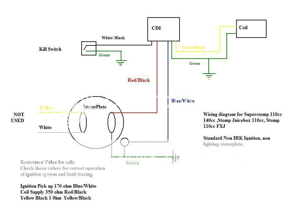
- Wiring Connections: Understanding the proper connections between components, including wire colors and terminal locations.
- Grounding: Establishing a proper grounding system to ensure electrical stability and prevent malfunctions.
- Ignition Timing: Setting the correct ignition timing for optimal engine performance and fuel efficiency.
- Lighting System: Wiring and connecting the lighting system, including headlights, taillights, and turn signals.
- Kill Switch: Installing and wiring the kill switch to safely stop the engine.
- Troubleshooting: Identifying and resolving common electrical issues using the wiring diagram.
- Safety Precautions: Following proper safety procedures while working with electrical systems.
- Customization: Understanding how to modify or customize the wiring diagram for specific needs or preferences.
These aspects collectively provide a comprehensive understanding of a CDI Kick Start Pit Bike Wiring Diagram Without Battery, enabling users to confidently design, troubleshoot, and maintain their electrical systems. By mastering these aspects, individuals can ensure the reliable and efficient operation of their pit bikes.
Component Identification
In the context of a CDI Kick Start Pit Bike Wiring Diagram Without Battery, component identification is of utmost importance. The accurate identification of electrical components forms the foundation for a properly functioning electrical system. Each component plays a specific and critical role in the overall operation of the pit bike.
The CDI unit, for instance, is responsible for generating the high-voltage spark that ignites the air-fuel mixture in the engine. The ignition coil amplifies the electrical current from the CDI unit to create the spark. The stator generates electricity that powers the CDI unit and other electrical components. The lighting system, including headlights, taillights, and turn signals, enhances visibility and safety during operation.
Precise identification of these components is crucial to ensure proper connections and functionality. Incorrect identification can lead to electrical malfunctions, poor performance, and even safety hazards. Therefore, it is essential to have a thorough understanding of the specific components involved in a CDI Kick Start Pit Bike Wiring Diagram Without Battery and their respective functions.
Wiring Connections
Wiring connections are critical in a CDI Kick Start Pit Bike Wiring Diagram Without Battery, ensuring the proper flow of electrical current between components. Mismatched wire colors or incorrect terminal connections can lead to electrical malfunctions, poor performance, and even safety hazards.
- Color Coding: Wires in a pit bike wiring diagram are typically color-coded to simplify identification and prevent errors. Each color represents a specific function or component, such as black for ground, red for power, and yellow for lighting.
- Terminal Types: Terminals vary in size, shape, and function, and must match the corresponding connectors on components. Common terminal types include bullet connectors, spade connectors, and ring terminals.
- Grounding: Establishing a proper ground connection is essential for electrical stability. The negative terminal of the battery or a designated grounding point on the frame provides a path for electrical current to flow back to the source.
- Ignition Timing: The CDI unit relies on precise ignition timing to generate the spark at the correct moment in the engine cycle. Incorrect wiring connections can affect ignition timing, impacting engine performance and fuel efficiency.
Understanding and adhering to proper wiring connections are paramount for a functional and reliable electrical system in a CDI Kick Start Pit Bike Without Battery. By meticulously following the wiring diagram and ensuring accurate connections, enthusiasts can maintain optimal performance, safety, and longevity of their pit bikes.
Grounding
In the context of a CDI Kick Start Pit Bike Wiring Diagram Without Battery, grounding plays a crucial role in ensuring electrical stability and preventing malfunctions. A proper grounding system provides a path for electrical current to flow back to the source, completing the electrical circuit and preventing voltage fluctuations and other issues.
- Frame Grounding: The frame of the pit bike typically serves as the main grounding point. A dedicated grounding wire connects the negative terminal of the CDI unit or battery (if present) to a clean, unpainted surface on the frame, ensuring a reliable electrical connection.
- Engine Grounding: The engine block or cylinder head may also require a separate grounding wire to prevent electrical interference and ensure proper operation of sensors and other electrical components.
- Battery Grounding: If a battery is used in the electrical system, it must be properly grounded to the frame or engine to provide a stable reference voltage and prevent electrical imbalances.
- Troubleshooting: Grounding issues can manifest in various ways, such as intermittent electrical problems, poor engine performance, or even electrical fires. Troubleshooting grounding involves checking the integrity of grounding connections, inspecting wires for damage or corrosion, and ensuring proper contact between metal surfaces.
Establishing a proper grounding system is essential for the reliable and safe operation of a CDI Kick Start Pit Bike Without Battery. By understanding the importance of grounding and following proper wiring practices, enthusiasts can minimize electrical issues, improve performance, and extend the lifespan of their pit bikes.
Ignition Timing
In the context of a CDI Kick Start Pit Bike Wiring Diagram Without Battery, ignition timing plays a critical role in determining the performance and efficiency of the engine. The CDI unit relies on precise timing to generate the spark at the optimal moment in the engine cycle, ensuring proper combustion and maximizing power output.
When ignition timing is set correctly, the air-fuel mixture in the combustion chamber ignites at the ideal time, leading to efficient combustion and optimal engine performance. This translates into increased power, improved throttle response, and reduced fuel consumption.
Conversely, incorrect ignition timing can have detrimental effects on engine operation. Advanced ignition timing can cause engine knocking, overheating, and reduced power, while retarded ignition timing can lead to poor starting, incomplete combustion, and increased emissions.
In a CDI Kick Start Pit Bike Without Battery, the ignition timing is typically set using a dedicated timing adjustment screw or dial on the CDI unit. By carefully adjusting the timing according to the manufacturer’s specifications or using a timing light, enthusiasts can optimize engine performance and fuel efficiency.
Understanding the importance of ignition timing and setting it correctly is essential for getting the most out of a CDI Kick Start Pit Bike Without Battery. Proper ignition timing ensures smooth operation, maximizes power, and prolongs engine life.
Lighting System
In the context of a CDI Kick Start Pit Bike Wiring Diagram Without Battery, the lighting system plays a crucial role in enhancing visibility and safety during operation, particularly in low-light conditions or at night. Wiring and connecting the lighting system involves understanding the proper connections between components, ensuring optimal functionality and compliance with legal requirements.
- Headlights: Headlights provide forward illumination, allowing riders to see the road ahead clearly. They are typically powered by a dedicated circuit and require proper wiring to the battery or CDI unit.
- Taillights: Taillights serve as safety devices, making the pit bike visible from behind. They are usually wired to the same circuit as the brake light and are essential for signaling braking intentions.
- Turn Signals: Turn signals indicate the rider’s intention to change direction and enhance safety by alerting other vehicles. They require proper wiring to a dedicated flasher unit.
- Wiring Harness: In many pit bikes, a pre-assembled wiring harness is used to simplify the installation and connection of the lighting system. This harness typically includes color-coded wires and connectors, making it easier to follow the wiring diagram.
Understanding the lighting system and its proper wiring is crucial for ensuring safe and legal operation of a CDI Kick Start Pit Bike Without Battery. By carefully following the wiring diagram and adhering to recommended practices, enthusiasts can enhance visibility, improve safety, and ensure compliance with regulations.
Kill Switch
In the context of a CDI Kick Start Pit Bike Wiring Diagram Without Battery, the kill switch serves as a critical safety component, enabling riders to quickly and effectively stop the engine in emergency situations or when necessary.
The kill switch works by interrupting the electrical circuit that powers the ignition system. When the kill switch is activated, the flow of electricity to the CDI unit is cut off, causing the engine to stop running immediately. This feature is essential for preventing uncontrolled movement of the pit bike and ensuring the safety of the rider and others.
Installing and wiring the kill switch properly is crucial for its reliable operation. The kill switch is typically mounted on the handlebars within easy reach of the rider’s thumb or fingers. The wiring involves connecting the kill switch to the CDI unit and the ground circuit. By following the wiring diagram and using appropriate connectors, enthusiasts can ensure that the kill switch functions as intended.
Real-life examples of the kill switch in action include scenarios where the rider needs to stop the engine quickly, such as when encountering obstacles, losing control, or experiencing mechanical issues. The kill switch allows the rider to respond promptly, minimizing the risk of accidents or further damage.
Understanding the importance of the kill switch and its proper installation and wiring empowers riders with an essential safety feature. It provides peace of mind and enhances the overall riding experience, making CDI Kick Start Pit Bikes Without Batteries safer and more enjoyable to operate.
Troubleshooting
In the realm of CDI Kick Start Pit Bike Wiring Diagrams Without Battery, troubleshooting plays a pivotal role in identifying and resolving electrical issues, ensuring optimal performance and safe operation. Understanding the wiring diagram empowers enthusiasts to diagnose and rectify common electrical problems, minimizing downtime and enhancing the overall riding experience.
- Electrical Component Inspection: Thoroughly inspecting electrical components, such as the CDI unit, ignition coil, and stator, for any signs of damage or loose connections can help identify potential issues. Visual inspection and testing with a multimeter can reveal faulty components that need replacement.
- Wire Continuity Testing: Using a multimeter to test the continuity of wires ensures that there are no breaks or damage in the electrical circuits. This process involves checking for continuity between different points in the wiring harness, identifying any sections with no electrical flow that may require repair or replacement.
- Ground Circuit Verification: Establishing a proper ground connection is crucial for electrical stability. Inspecting the grounding points, including the frame and engine block, for corrosion or loose connections can prevent intermittent electrical issues and ensure reliable operation.
- Ignition Timing Adjustment: Incorrect ignition timing can lead to poor engine performance and difficulty starting. Using a timing light or following the manufacturer’s specifications, enthusiasts can adjust the ignition timing to optimize engine operation and maximize power output.
Troubleshooting common electrical issues using the wiring diagram empowers riders to maintain their CDI Kick Start Pit Bikes Without Battery in optimal condition. By understanding the function of each component and the flow of electricity through the system, they can identify and resolve problems efficiently, ensuring a safe and enjoyable riding experience.
Safety Precautions
When working with electrical systems, particularly in the context of a CDI Kick Start Pit Bike Wiring Diagram Without Battery, adhering to proper safety procedures is of paramount importance. These precautions serve as a critical foundation for ensuring the safety of individuals and preventing potential hazards associated with electrical work.
Electrical systems, if not handled with due care, can pose significant risks, including electrical shocks, fires, and explosions. Safety precautions provide a structured framework to mitigate these risks by outlining specific guidelines and practices that must be followed while working with electrical components and circuits.
In the realm of CDI Kick Start Pit Bike Wiring Diagrams Without Battery, safety precautions are an integral part of the overall wiring process. Negligence in adhering to these precautions can lead to incorrect wiring, faulty connections, and potential electrical hazards. By following proper safety procedures, enthusiasts can minimize the likelihood of accidents and ensure the safe and reliable operation of their pit bikes.
Some common safety precautions include:
- Disconnecting the battery or power source before performing any electrical work.
- Using insulated tools and wearing appropriate personal protective equipment (PPE).
- Inspecting wires and components for damage or wear before making connections.
- Following the wiring diagram carefully and double-checking connections.
- Testing the circuit for proper functionality before energizing it.
By incorporating these safety precautions into their electrical work, individuals can effectively reduce the risks associated with CDI Kick Start Pit Bike Wiring Diagrams Without Battery and ensure a safe and enjoyable riding experience.
Customization
In the realm of “Cdi Kick Start Pit Bike Wiring Diagram Without Battery”, customization plays a significant role in tailoring the electrical system to specific requirements or preferences. It empowers enthusiasts to modify the wiring diagram to suit their unique needs, enhance performance, or incorporate additional features.
- Component Selection: Understanding the electrical components available and their compatibility with the existing wiring diagram allows for the integration of custom components, such as upgraded lighting systems, performance ignition coils, or specialized sensors.
- Circuit Modifications: Customizing the wiring diagram involves modifying existing circuits or adding new ones. This may include altering wire routing, adding relays or switches, or incorporating additional safety features to meet specific operational requirements.
- Performance Enhancement: Customization can be leveraged to optimize engine performance by adjusting ignition timing, modifying the charging system, or installing a custom exhaust system. These modifications require careful planning and execution to ensure optimal results.
- Accessory Integration: The wiring diagram can be customized to accommodate various accessories, such as GPS devices, heated grips, or auxiliary lighting. This involves adding dedicated circuits, switches, and connectors to seamlessly integrate these accessories into the electrical system.
Customizing a “Cdi Kick Start Pit Bike Wiring Diagram Without Battery” requires a thorough understanding of electrical principles, careful planning, and meticulous execution. By incorporating these modifications, enthusiasts can tailor their pit bikes to meet their specific needs, enhance performance, and create a truly unique riding experience.


![[DIAGRAM] Pit Bike Wiring Diagram Electric Start](https://i0.wp.com/i106.photobucket.com/albums/m260/mattisbatman/wiring.gif?w=665&ssl=1)

Related Posts


