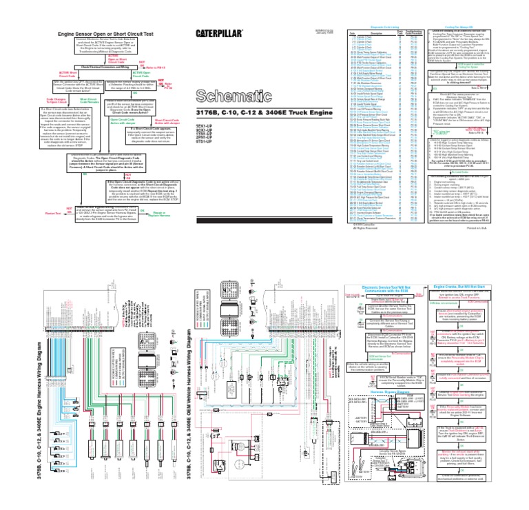
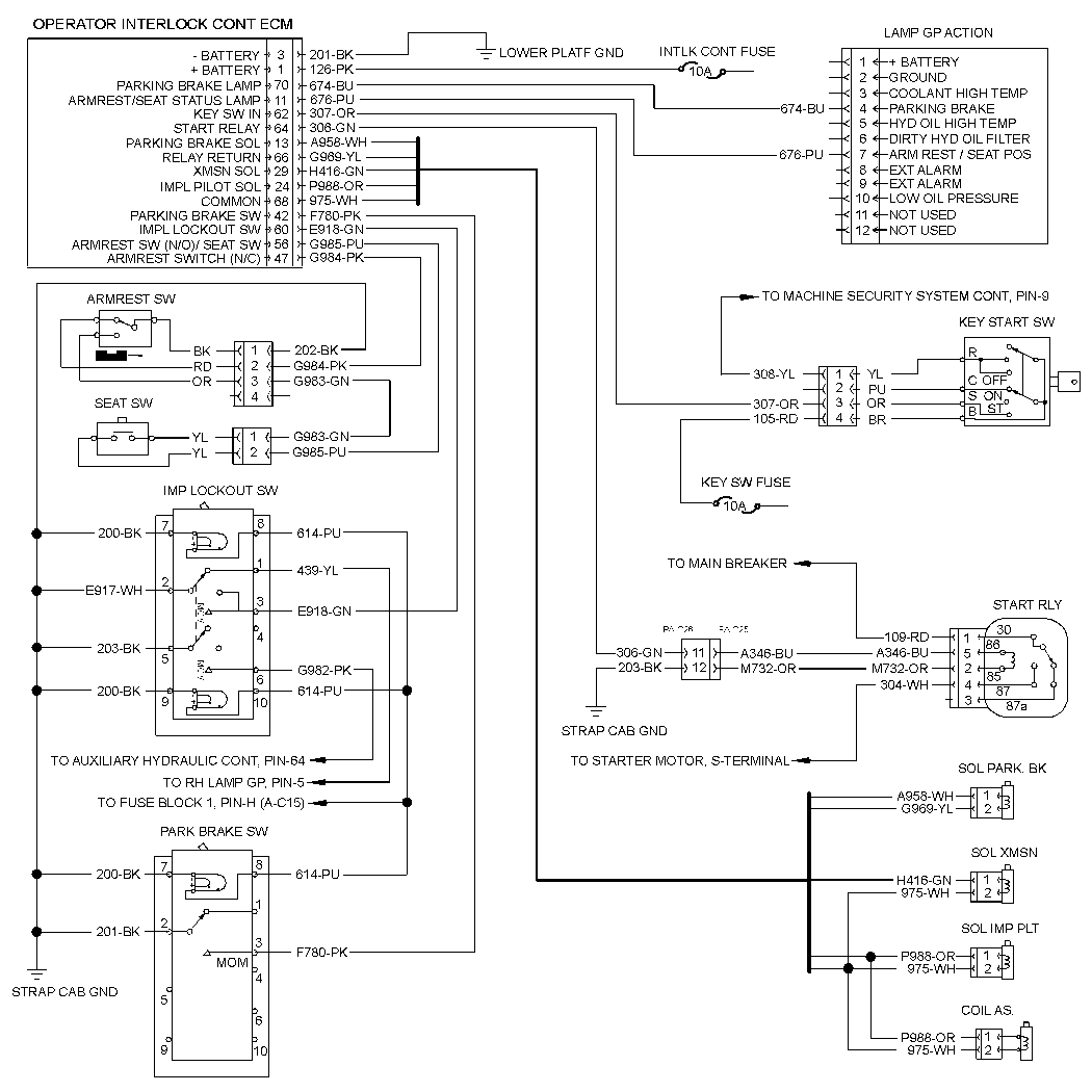
A Cat 40 Pin ECM Wiring Diagram is a detailed schematic that outlines the electrical connections between the engine control module (ECM) and various sensors, actuators, and other components within a CAT (Caterpillar) engine system. It provides a visual representation of the wiring harness layout, allowing technicians to troubleshoot electrical issues, diagnose faults, and perform repairs.
The Cat 40 Pin ECM Wiring Diagram is essential for maintaining and servicing CAT engines, ensuring optimal performance and reliability. It enables technicians to identify and locate specific wiring connections, trace signal paths, and verify proper electrical continuity. Additionally, the diagram serves as a valuable reference for modifications and upgrades to the engine system.
The development of standardized wiring diagrams, such as the Cat 40 Pin ECM Wiring Diagram, has been a critical advancement in the field of engine diagnostics and repair. It has simplified the troubleshooting process, reduced downtime, and improved the overall efficiency of engine maintenance and repair operations.
The Cat 40 Pin ECM Wiring Diagram, a detailed schematic outlining the electrical connections within a CAT engine system, plays a pivotal role in maintaining and repairing such engines. Understanding the essential aspects of this diagram is crucial for effective troubleshooting and servicing.
- Schematic Representation: It provides a visual representation of the wiring harness layout, enabling technicians to trace signal paths and identify specific connections.
- Troubleshooting Guide: The diagram aids in diagnosing electrical faults by pinpointing potential issues and guiding repair processes.
- Maintenance Reference: It serves as a valuable reference for routine maintenance tasks, such as sensor replacement and wire harness inspection.
- Modification and Upgrade Guide: The diagram assists in implementing modifications and upgrades to the engine system, ensuring compatibility and proper functionality.
- Engine Performance Optimization: By ensuring accurate wiring connections, the diagram contributes to optimal engine performance and reliability.
- Reduced Downtime: It facilitates efficient troubleshooting and repair, minimizing engine downtime and maximizing productivity.
- Improved Safety: Proper wiring ensures electrical safety, preventing potential hazards and accidents.
- Standardized Documentation: The Cat 40 Pin ECM Wiring Diagram conforms to standardized industry practices, ensuring consistency and ease of use across different engine models.
These aspects collectively underscore the importance of the Cat 40 Pin ECM Wiring Diagram in the maintenance, repair, and operation of CAT engine systems. It empowers technicians with the knowledge and guidance necessary to keep these engines running smoothly and efficiently, ultimately contributing to the success of various industrial and commercial applications.
Schematic Representation
The schematic representation in the Cat 40 Pin ECM Wiring Diagram is a critical component for effective engine diagnostics and repair. It provides a visual representation of the wiring harness layout, enabling technicians to trace signal paths and identify specific connections, which is essential for troubleshooting electrical faults and ensuring proper engine operation.
Without a schematic representation, technicians would have to rely solely on physical inspection of the wiring harness, which can be time-consuming and error-prone. The schematic provides a clear and concise overview of the electrical connections, allowing technicians to quickly identify potential issues and make informed decisions about repairs.
For example, if a sensor is malfunctioning, the technician can use the schematic to trace the signal path from the sensor to the ECM, checking for any breaks or shorts in the wiring. This systematic approach significantly reduces troubleshooting time and helps ensure accurate repairs.
Additionally, the schematic representation is crucial for modifications and upgrades to the engine system. By providing a visual representation of the existing wiring harness, technicians can plan and implement changes efficiently, ensuring compatibility and proper functionality.
In summary, the schematic representation in the Cat 40 Pin ECM Wiring Diagram is a vital tool for engine diagnostics, repair, and modification. It enables technicians to trace signal paths, identify specific connections, and make informed decisions about electrical issues, ultimately contributing to the optimal performance and reliability of CAT engine systems.
Troubleshooting Guide
Within the comprehensive Cat 40 Pin ECM Wiring Diagram, the troubleshooting guide stands as a crucial component, empowering technicians to diagnose electrical faults with precision and efficiency. It serves as a systematic roadmap, pinpointing potential issues and guiding repair processes to ensure optimal engine performance.
- Rapid Fault Identification: The diagram enables technicians to quickly identify potential electrical faults by providing a visual representation of the wiring harness layout. By tracing signal paths and examining connections, they can pinpoint the source of issues, reducing troubleshooting time.
- Targeted Repair Solutions: Based on the identified fault, the diagram guides technicians through targeted repair processes. It provides insights into the specific components and connections that require attention, ensuring efficient and effective repairs.
- Real-World Examples: Consider a scenario where an engine sensor malfunctions. The troubleshooting guide in the Cat 40 Pin ECM Wiring Diagram allows technicians to trace the signal path from the sensor to the ECM, identifying any breaks or shorts in the wiring. This targeted approach facilitates accurate repairs, minimizing downtime.
- Implications for Engine Performance: Accurate troubleshooting and repairs guided by the diagram contribute directly to optimal engine performance. By resolving electrical faults promptly, technicians can prevent potential engine damage, enhance reliability, and maintain peak efficiency.
In summary, the troubleshooting guide within the Cat 40 Pin ECM Wiring Diagram is an invaluable asset for engine diagnostics and repair. It enables technicians to pinpoint electrical faults swiftly and guide targeted repair processes, ultimately ensuring the reliable and efficient operation of CAT engine systems.
Maintenance Reference
Within the comprehensive Cat 40 Pin ECM Wiring Diagram, the maintenance reference aspect emerges as a crucial component, providing invaluable guidance for routine maintenance tasks. It serves as a comprehensive resource for technicians, ensuring the optimal performance and reliability of CAT engine systems.
- Sensor Replacement: The diagram provides detailed instructions for sensor replacement, including the identification of specific sensors, their locations, and the proper procedures for removal and installation. This information is critical for maintaining accurate sensor data and ensuring optimal engine operation.
- Wire Harness Inspection: The diagram serves as a valuable reference for wire harness inspection, guiding technicians in identifying potential damage, corrosion, or loose connections. Regular inspection and maintenance of the wire harness prevent electrical faults, ensuring reliable signal transmission and overall engine performance.
- Maintenance Intervals: The maintenance reference section within the Cat 40 Pin ECM Wiring Diagram often includes recommended maintenance intervals for various components, such as sensors and wire harnesses. Adhering to these intervals helps prevent premature failures and extends the lifespan of engine systems.
- Real-World Examples: Consider a scenario where a temperature sensor malfunctions, leading to inaccurate readings. The maintenance reference in the Cat 40 Pin ECM Wiring Diagram provides step-by-step instructions for identifying the faulty sensor, its location, and the correct replacement procedure. This information empowers technicians to perform efficient repairs, minimizing downtime and ensuring accurate engine operation.
In summary, the maintenance reference aspect of the Cat 40 Pin ECM Wiring Diagram is a comprehensive resource for routine maintenance tasks, providing detailed instructions, recommended intervals, and real-world examples. By leveraging this information, technicians can effectively maintain and repair CAT engine systems, ensuring optimal performance and reliability.
Modification and Upgrade Guide
The Cat 40 Pin ECM Wiring Diagram serves as a critical component for implementing modifications and upgrades to CAT engine systems. It provides a comprehensive guide, ensuring compatibility and proper functionality throughout the modification process.
The diagram acts as a roadmap, outlining the electrical connections and signal paths within the engine system. When modifications or upgrades are necessary, technicians rely on this guide to understand the impact on the existing wiring harness. It helps them identify potential conflicts, plan the integration of new components, and ensure seamless operation.
For instance, consider the scenario of upgrading the fuel injection system. The Cat 40 Pin ECM Wiring Diagram provides insights into the electrical connections of the existing system, allowing technicians to determine the compatibility of the new components. It guides them in modifying the wiring harness to accommodate the upgraded fuel injectors and sensors, ensuring optimal performance and reliability.
Furthermore, the diagram is crucial for maintaining proper functionality after modifications or upgrades. It enables technicians to verify the accuracy of the new electrical connections, troubleshoot any issues that may arise, and ensure that the engine system operates as intended.
In summary, the Modification and Upgrade Guide within the Cat 40 Pin ECM Wiring Diagram is a vital resource for implementing modifications and upgrades to CAT engine systems. It provides a comprehensive guide, ensuring compatibility, proper functionality, and optimal performance throughout the process.
Engine Performance Optimization
Within the comprehensive Cat 40 Pin ECM Wiring Diagram, the aspect of engine performance optimization stands as a cornerstone, ensuring the seamless operation and reliability of CAT engine systems. By providing accurate wiring connections, the diagram contributes to optimal engine performance in several critical ways:
- Optimized Fuel Efficiency: Accurate wiring connections ensure the precise delivery of fuel to the engine’s cylinders, optimizing combustion and minimizing fuel wastage. This contributes directly to improved fuel efficiency, reducing operational costs and environmental impact.
- Reduced Emissions: Accurate wiring connections enable efficient communication between sensors and the ECM, ensuring optimal air-fuel ratios and minimizing harmful emissions. This contributes to cleaner engine operation and compliance with environmental regulations.
- Enhanced Power Output: The diagram ensures proper electrical connections to ignition components, such as spark plugs and injectors, maximizing spark energy and fuel delivery. This results in enhanced power output, improved acceleration, and overall engine performance.
- Increased Durability: Accurate wiring connections prevent electrical faults and ensure stable power supply to critical engine components. This reduces wear and tear on components, prolongs engine life, and minimizes the need for costly repairs.
In conclusion, the Cat 40 Pin ECM Wiring Diagram plays a pivotal role in optimizing engine performance and reliability by ensuring accurate wiring connections. These connections contribute to improved fuel efficiency, reduced emissions, enhanced power output, and increased durability, ultimately maximizing the performance and lifespan of CAT engine systems.
Reduced Downtime
Within the comprehensive Cat 40 Pin ECM Wiring Diagram, the aspect of reduced downtime stands as a critical factor, contributing to the overall efficiency and productivity of engine systems. By facilitating efficient troubleshooting and repair, the diagram minimizes engine downtime, ensuring optimal performance and maximizing productivity.
- Rapid Troubleshooting: The diagram provides a clear visual representation of the wiring harness layout, enabling technicians to quickly identify and locate potential issues. This rapid troubleshooting process minimizes downtime by reducing the time spent on diagnostics and fault isolation.
- Targeted Repairs: The diagram guides technicians through targeted repair processes, ensuring that only the necessary components are replaced or repaired. This focused approach reduces downtime by eliminating unnecessary work and ensuring that the engine is restored to optimal operating condition promptly.
- Real-World Example: Consider a scenario where an engine experiences a sudden loss of power. The Cat 40 Pin ECM Wiring Diagram allows technicians to quickly trace the electrical connections from the ECM to the affected components, identifying a faulty sensor as the root cause. This targeted troubleshooting and repair minimize downtime and restore engine performance.
- Implications for Productivity: Reduced downtime directly translates to increased productivity. By minimizing the time spent on repairs and maintenance, the Cat 40 Pin ECM Wiring Diagram contributes to the overall efficiency and productivity of engine systems, maximizing uptime and optimizing operational output.
In conclusion, the Reduced Downtime aspect of the Cat 40 Pin ECM Wiring Diagram is crucial for maintaining optimal engine performance and maximizing productivity. Through efficient troubleshooting and targeted repairs, the diagram minimizes downtime, allowing engine systems to operate at peak efficiency and contribute to the overall success of various industrial and commercial applications.
Improved Safety
Within the comprehensive Cat 40 Pin ECM Wiring Diagram, the aspect of improved safety holds paramount importance, ensuring the reliable and hazard-free operation of engine systems. Proper wiring plays a pivotal role in preventing potential electrical hazards and accidents, contributing to a safe and efficient work environment.
- Hazard Mitigation: Proper wiring connections eliminate loose or exposed wires, reducing the risk of electrical shocks and fires. This proactive approach ensures the safety of operators and personnel working around engine systems.
- Short Circuit Prevention: The diagram guides technicians in avoiding short circuits by ensuring proper insulation and segregation of electrical wires. Short circuits can lead to overheating, component damage, and even fires, posing significant safety risks. By preventing these incidents, the diagram contributes to a safer operating environment.
- Ground Fault Protection: The Cat 40 Pin ECM Wiring Diagram provides insights into proper grounding techniques, ensuring that electrical faults are safely discharged to the ground. This prevents the buildup of dangerous voltages on equipment frames or other surfaces, minimizing the risk of electrical shocks.
- Compliance with Safety Standards: The diagram adheres to industry-recognized safety standards and regulations, ensuring that engine systems meet the required safety criteria. This compliance helps organizations maintain a safe and compliant work environment, reducing the likelihood of accidents and liabilities.
In conclusion, the Cat 40 Pin ECM Wiring Diagram plays a crucial role in improving safety by providing guidelines for proper wiring practices. These practices eliminate electrical hazards, prevent accidents, and ensure the safe and reliable operation of engine systems. By prioritizing safety, the diagram contributes to a work environment where operators and personnel can perform their duties with confidence, reducing downtime and maximizing productivity.
Standardized Documentation
Within the realm of engine diagnostics and maintenance, standardized documentation stands as a cornerstone for effective communication and efficient troubleshooting. The Cat 40 Pin ECM Wiring Diagram exemplifies this principle, adhering to established industry practices to ensure consistency and ease of use across a wide range of engine models.
This standardized documentation serves as a common language, enabling technicians and engineers to seamlessly navigate the complexities of various engine systems. By adhering to industry-recognized conventions for wire colors, connector types, and signal protocols, the Cat 40 Pin ECM Wiring Diagram facilitates rapid identification of components and accurate interpretation of electrical signals.
For instance, in a scenario where a technician encounters an electrical fault in a Cat engine, the standardized wiring diagram provides a systematic roadmap for troubleshooting. The consistent use of color-coding and logical organization allows technicians to quickly trace signal paths, identify potential issues, and implement targeted repairs.
Moreover, standardized documentation promotes knowledge transfer and collaboration within the industry. Technicians from different backgrounds can readily understand and apply the Cat 40 Pin ECM Wiring Diagram, fostering a shared understanding of engine systems and enabling efficient problem-solving.
In summary, the standardized documentation of the Cat 40 Pin ECM Wiring Diagram is a critical component, ensuring consistency, ease of use, and effective communication across different engine models. It empowers technicians with a common language for troubleshooting, facilitates knowledge transfer, and ultimately contributes to the reliable and efficient operation of Cat engine systems.


Related Posts


