A Brainpower Motor Controller Wiring Diagram represents a detailed plan for connecting individual components within a motor controller system manufactured by Brainpower. These diagrams guide electrical installations to ensure proper operation, safety, and performance of the motor controller.
Understanding and utilizing motor controller wiring diagrams are crucial during system setup and maintenance. They benefit engineers, technicians, and hobbyists who need to install, troubleshoot, or modify motor control systems effectively. A key historical development in motor controller wiring diagrams was the advent of standardized color codes for wire connections, enhancing ease of identification and reducing installation errors.
In this article, we will delve deeper into the essential components of a Brainpower Motor Controller Wiring Diagram, its practical applications, and vital safety considerations.
Understanding the key aspects of a Brainpower Motor Controller Wiring Diagram is crucial for ensuring proper installation, operation, and maintenance of motor control systems.
- Components: Essential elements of the wiring diagram, including power supply, motor, controller, sensors, and other devices.
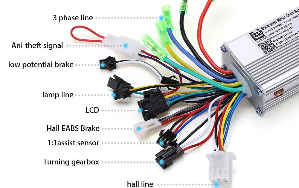
- Connections: Depiction of electrical connections between components, indicating wire colors, gauges, and terminals.
- Layout: Physical arrangement of components and wiring within the system.
- Color Codes: Standardized colors assigned to wires for easy identification and reduced errors.
- Symbols: Graphical representations of components and connections, following industry standards.
- Ratings: Specifications of voltage, current, and power handling capacities for each component.
- Safety Features: Protective measures incorporated in the diagram, such as fuses, circuit breakers, and grounding.
- Troubleshooting: Guidance for diagnosing and resolving common issues based on the wiring diagram.
- Customization: Flexibility to modify the diagram to meet specific application requirements.
These aspects are interconnected and essential for understanding the functionality, safety, and efficiency of the motor controller system. Proper interpretation of the wiring diagram allows engineers and technicians to make informed decisions during installation, maintenance, and troubleshooting.
Components
Within the context of a Brainpower Motor Controller Wiring Diagram, the components section holds utmost importance as it outlines the essential building blocks of the motor control system. Understanding the different components, their interconnections, and their functions is crucial for successful implementation, operation, and troubleshooting.
- Power Supply: The lifeline of the system, providing electrical energy to the motor controller and connected devices. It can be a battery, power adapter, or other voltage source.
- Motor: The electromechanical device that converts electrical energy into mechanical motion. Its specifications, such as voltage, power, and speed, must align with the controller’s capabilities.
- Controller: The brain of the system, receiving input signals and generating output commands to control the motor’s operation. Various types of controllers exist, including PID, PWM, and servo controllers.
- Sensors: Devices that monitor and provide feedback on system parameters, such as motor speed, position, and temperature. They enable closed-loop control and protection mechanisms.
These components, along with other auxiliary devices like switches, relays, and connectors, work in harmony to achieve the desired motor control functionality. The wiring diagram serves as a roadmap, guiding the proper connection and integration of these components, ensuring efficient and reliable system operation.
Connections
In the context of a Brainpower Motor Controller Wiring Diagram, the connections section plays a pivotal role as it meticulously outlines the electrical interconnections between various components within the motor control system. Each connection is carefully defined, including details such as wire colors, gauges, and terminals, ensuring precise and reliable system operation. Without a clear understanding of these connections, the wiring diagram would be rendered ineffective.
Wire colors, in particular, adhere to standardized color codes, providing a universal language for electrical installations. This color-coding system simplifies the identification of wires, reduces the risk of errors during installation and maintenance, and facilitates troubleshooting. Furthermore, the specified wire gauges ensure that the appropriate wire size is used for the given current and voltage requirements, preventing overheating and ensuring system safety.
Practically speaking, accurate connections are essential for the proper functioning of the motor controller system. Incorrect wiring can lead to malfunctions, damage to components, or even safety hazards. For instance, reversing the polarity of the motor connections can cause the motor to run in the wrong direction or even overheat. Therefore, adhering strictly to the wiring diagram is paramount to avoid such issues.
In summary, the connections section of a Brainpower Motor Controller Wiring Diagram is not merely a collection of lines and symbols; it is a critical blueprint for establishing a functional and safe motor control system. Understanding and meticulously following these connections is crucial for engineers, technicians, and hobbyists alike, ensuring that the system operates as intended and meets the desired performance and safety standards.
Layout
Within the context of a Brainpower Motor Controller Wiring Diagram, the layout section holds great significance as it defines the physical arrangement of components and wiring within the motor control system. This layout is not merely a matter of aesthetics but rather a critical aspect influencing the system’s functionality, safety, and maintainability.
The layout of components and wiring directly impacts factors such as signal integrity, heat dissipation, and accessibility for maintenance. Proper spacing between components ensures minimal electromagnetic interference, preventing signal distortion and maintaining reliable communication. Adequate heat dissipation is crucial to prevent overheating and potential damage to components, and the layout should allow for proper airflow and heat transfer. Strategic placement of components also considers ease of access for maintenance, troubleshooting, and future modifications.
Real-life examples abound where careful attention to layout has resulted in improved system performance and reliability. In industrial settings, motor controllers are often installed in enclosed cabinets or panels where space is limited. A well-planned layout optimizes the use of available space, allowing for efficient heat dissipation and ease of maintenance. In automotive applications, motor controllers are subjected to vibrations and harsh environmental conditions. A robust layout ensures that components are securely mounted and wiring is protected from damage, enhancing the system’s durability and reliability.
Understanding the importance of layout in Brainpower Motor Controller Wiring Diagrams empowers engineers and technicians to design and implement systems that meet specific requirements and constraints. By considering factors such as signal integrity, heat dissipation, and accessibility, they can create systems that operate reliably, efficiently, and safely over their intended lifespan.
Color Codes
Within the context of Brainpower Motor Controller Wiring Diagrams, color codes play a pivotal role in simplifying the identification and connection of wires, leading to reduced errors and enhanced system reliability. The use of standardized color codes is a critical component of these diagrams, ensuring consistency across different systems and promoting industry-wide best practices.
The assignment of specific colors to different wire functions has been meticulously established, providing a universal language for electrical installations. This color-coding scheme enables engineers and technicians to quickly identify the purpose of each wire, even in complex systems with numerous connections. By adhering to these color codes, they can minimize the risk of misconnections, which can lead to malfunctions, damage to equipment, or safety hazards.
Practical applications of color codes in Brainpower Motor Controller Wiring Diagrams abound in various industries. In industrial automation systems, color codes allow for efficient and accurate wiring of motors, sensors, and other devices. This is particularly important in large-scale systems where numerous wires are bundled together, making it challenging to distinguish between them. Color-coded wires simplify the installation and maintenance processes, reducing downtime and increasing productivity.
In summary, the use of standardized color codes in Brainpower Motor Controller Wiring Diagrams is a critical factor contributing to the reliability, safety, and maintainability of electrical systems. By employing these color codes, engineers and technicians can ensure accurate connections, minimize errors, and enhance the overall efficiency of motor control systems.
Symbols
Within the context of Brainpower Motor Controller Wiring Diagrams, symbols play a critical role in conveying complex electrical information in a simplified and standardized manner. These graphical representations of components and connections adhere to industry-established norms, ensuring universal understanding and reducing the risk of misinterpretation.
- Component Representation: Symbols provide graphical representations of various components used in motor controller systems, such as motors, sensors, controllers, and power sources. These symbols are universally recognized, enabling engineers and technicians to quickly identify and understand the system’s architecture.
- Connection Types: Symbols also depict different types of connections between components, such as power connections, signal connections, and grounding connections. Clear and consistent symbols for these connections simplify the wiring process and enhance system reliability.
- Signal Flow: In complex systems with multiple signal paths, symbols can effectively illustrate the flow of signals and data. This visual representation aids in troubleshooting and maintenance, allowing engineers to trace signal paths and identify potential issues.
- Standardization Benefits: By adhering to industry-standard symbols, Brainpower Motor Controller Wiring Diagrams promote consistency and clarity across different systems and projects. This standardization facilitates collaboration, reduces errors, and ensures that all stakeholders have a common understanding of the system’s design and functionality.
In summary, the use of graphical symbols in Brainpower Motor Controller Wiring Diagrams is essential for effective communication, error reduction, and simplified system design. By leveraging standardized symbols, engineers and technicians can create and interpret wiring diagrams with confidence, ensuring the proper installation, operation, and maintenance of motor control systems.
Ratings
Within the context of a Brainpower Motor Controller Wiring Diagram, ratings hold critical importance as they define the electrical specifications and limitations of each component within the motor control system. These ratings directly influence the wiring design, component selection, and overall system performance.
Voltage, current, and power ratings determine the maximum electrical parameters that each component can safely handle without compromising its functionality or causing damage. By adhering to these ratings, engineers and technicians can ensure that the system operates within its intended operating range, preventing failures, accidents, and costly repairs.
Practical examples abound where ignoring component ratings in Brainpower Motor Controller Wiring Diagrams has led to disastrous consequences. Oversizing or undersizing wires based on current ratings can result in overheating, insulation breakdown, or even fire hazards. Similarly, exceeding voltage or power ratings of components can lead to premature failure, reduced lifespan, or catastrophic damage.
Understanding and applying component ratings in Brainpower Motor Controller Wiring Diagrams is not only essential for safety but also for optimizing system performance. By selecting components with appropriate ratings, engineers can ensure that the system operates efficiently, reliably, and within its design constraints. This understanding also enables informed decision-making regarding system upgrades, maintenance intervals, and troubleshooting procedures.
Safety Features
In the realm of Brainpower Motor Controller Wiring Diagrams, safety features play a paramount role in safeguarding the integrity of the system and preventing potential hazards. These protective measures are meticulously incorporated into the diagram to ensure the safety of personnel, equipment, and the environment.
- Fuses: Essential components designed to interrupt excessive current flow, protecting against short circuits and electrical faults. Fuses are rated for specific amperage and voltage thresholds, ensuring that they blow before damage occurs to other components.
- Circuit Breakers: Similar to fuses, circuit breakers provide overcurrent protection but can be manually reset after tripping, eliminating the need for fuse replacement. They offer adjustable trip settings, allowing for customization based on system requirements.
- Grounding: A crucial safety measure that establishes a low-resistance path to the ground, preventing dangerous voltage buildup on equipment enclosures. Proper grounding minimizes the risk of electrical shock and ensures that fault currents are safely discharged.
- Emergency Stop Switches: In the event of an emergency, these switches provide a quick and convenient way to disconnect power to the motor controller, halting all motor operation. They are typically large, red buttons prominently placed for easy access.
By incorporating these safety features into Brainpower Motor Controller Wiring Diagrams, engineers can create systems that comply with industry regulations, minimize downtime, and ensure the well-being of those interacting with the equipment. These measures serve as a testament to the importance of safety in electrical design and provide a solid foundation for reliable and hazard-free operation.
Troubleshooting
Within the context of Brainpower Motor Controller Wiring Diagrams, the troubleshooting section holds immense importance as it provides invaluable guidance for diagnosing and resolving common issues that may arise during system installation, operation, and maintenance. This section is an indispensable component of the overall wiring diagram, empowering engineers, technicians, and end-users to effectively identify and address potential problems.
The troubleshooting section typically includes a systematic approach to fault-finding, often presented in a step-by-step format. It may include specific instructions for checking wire connections, testing components, and analyzing error codes. By following these steps, users can isolate the root cause of the issue and implement appropriate corrective actions.
Real-life examples abound where the troubleshooting section of Brainpower Motor Controller Wiring Diagrams has proven invaluable. Consider a scenario where a motor is not responding as expected. By referring to the wiring diagram and following the troubleshooting steps, a technician can quickly check the power supply, wire connections, and motor terminals. This systematic approach helps pinpoint the issue, whether it’s a loose connection, a faulty component, or a programming error.
The practical significance of understanding the troubleshooting section in Brainpower Motor Controller Wiring Diagrams cannot be overstated. It empowers individuals to:
- Reduce downtime by quickly identifying and resolving issues.
- Minimize the risk of damage to equipment and components.
- Enhance system reliability and performance.
- Ensure safe and efficient operation of motor control systems.
In conclusion, the troubleshooting section of Brainpower Motor Controller Wiring Diagrams is a critical resource for maintaining optimal system performance and resolving common issues. By providing a systematic approach to fault-finding and repair, this section empowers users to diagnose and address problems effectively, minimizing downtime and ensuring the safety and reliability of motor control systems.
Customization
Within the context of Brainpower Motor Controller Wiring Diagrams, the aspect of customization holds paramount importance as it empowers users to tailor the diagram to meet the unique requirements of their specific application. This flexibility allows for modifications that optimize system performance, enhance functionality, and ensure compatibility with a wide range of scenarios.
- Component Selection: The ability to select and incorporate specific components, such as sensors, relays, and resistors, enables the customization of the motor controller system to meet specific functional needs and performance requirements.
- Wiring Modifications: The flexibility to modify wire connections, routing, and termination points allows for adaptation to different motor types, control algorithms, and physical constraints, ensuring optimal system operation.
- Signal Conditioning: Customization of signal conditioning circuits, such as filtering, amplification, and isolation, enables the integration of sensors and other devices with varying signal characteristics, ensuring accurate and reliable data acquisition.
- Expansion and Integration: The ability to expand and integrate the wiring diagram with additional modules, such as communication interfaces, data loggers, and external control devices, allows for enhanced functionality and seamless integration into larger systems.
The customization capabilities of Brainpower Motor Controller Wiring Diagrams empower engineers and technicians to create tailored solutions that meet the demands of diverse applications. From industrial automation to robotics and renewable energy systems, the flexibility to modify the diagram ensures optimal performance, reliability, and compatibility, ultimately contributing to successful system implementation and operation.

![[7+] Brainpower Motor Controller , Tutorial1 Elektronik](https://i0.wp.com/images-na.ssl-images-amazon.com/images/I/61FsASM9niL._AC_SX679_.jpg?w=665&ssl=1)


Related Posts


