A Bosch 4 Wire O2 Sensor Wiring Diagram is a schematic representation of the electrical connections between a Bosch 4-wire oxygen sensor and other engine components. It provides a clear and concise way to understand and troubleshoot the sensor’s operation.
Bosch 4 Wire O2 Sensor Wiring Diagrams are important because they ensure that the sensor is properly installed and functioning correctly. A faulty O2 sensor can lead to poor engine performance, increased emissions, and decreased fuel economy. The diagram also provides information about the sensor’s ground, heater, and signal wires, which can be helpful for diagnostic purposes.
One key historical development in the field of oxygen sensors was the introduction of the Bosch 4-wire O2 sensor in the early 1990s. This sensor was a significant improvement over previous designs because it provided a more accurate and reliable signal. The 4-wire design also allowed for the incorporation of a heater element, which reduced the sensor’s warm-up time and improved its performance at low temperatures.
The information provided in this article will help you to understand the Bosch 4 Wire O2 Sensor Wiring Diagram and its importance. It will also provide you with tips on how to troubleshoot the sensor if you are experiencing problems.
The Bosch 4 Wire O2 Sensor Wiring Diagram is a crucial component of any engine management system. It provides a clear and concise way to understand and troubleshoot the sensor’s operation. Some of the most important aspects of the wiring diagram include:
- Sensor type: The type of oxygen sensor being used.
- Wiring harness: The specific wiring harness that is used to connect the sensor to the engine management system.
- Connector type: The type of connector that is used to connect the sensor to the wiring harness.
- Wire colors: The colors of the wires that are used to connect the sensor to the engine management system.
- Pin assignments: The specific pins on the connector that are used to connect the sensor to the engine management system.
- Ground connection: The location of the ground connection for the sensor.
- Heater circuit: The specific circuit that is used to heat the sensor.
- Signal circuit: The specific circuit that is used to send the sensor’s signal to the engine management system.
- Calibration data: The specific calibration data that is used to calibrate the sensor.
- Diagnostic procedures: The specific diagnostic procedures that can be used to troubleshoot the sensor.
These aspects are all essential for ensuring that the Bosch 4 Wire O2 Sensor Wiring Diagram is properly installed and functioning correctly. If any of these aspects are not correct, the sensor may not be able to provide accurate readings to the engine management system. This can lead to poor engine performance, increased emissions, and decreased fuel economy.
Sensor type
The type of oxygen sensor being used is a critical component of the Bosch 4 Wire O2 Sensor Wiring Diagram. This is because the type of sensor will determine the specific wiring and calibration data that is required. There are two main types of oxygen sensors: zirconia and titania. Zirconia sensors are the most common type and are used in a wide variety of applications. Titania sensors are less common and are typically used in high-performance applications.
The Bosch 4 Wire O2 Sensor Wiring Diagram is designed to work with either type of sensor. However, it is important to use the correct wiring and calibration data for the specific type of sensor that is being used. If the incorrect wiring or calibration data is used, the sensor may not be able to provide accurate readings to the engine management system. This can lead to poor engine performance, increased emissions, and decreased fuel economy.
Real-world examples of the Bosch 4 Wire O2 Sensor Wiring Diagram can be found in a wide variety of vehicles. Some of the most common applications include:
- Passenger cars
- Light trucks
- SUVs
- Motorcycles
- Marine engines
The practical applications of understanding the relationship between the sensor type and the wiring diagram are numerous. For example, this understanding can be used to:
- Troubleshoot problems with the oxygen sensor
- Install an oxygen sensor in a new vehicle
- Upgrade the oxygen sensor in an existing vehicle
Overall, the type of oxygen sensor being used is a critical component of the Bosch 4 Wire O2 Sensor Wiring Diagram. By understanding the relationship between the sensor type and the wiring diagram, you can ensure that the sensor is properly installed and functioning correctly.
Wiring harness
The wiring harness is a critical component of the Bosch 4 Wire O2 Sensor Wiring Diagram. It provides the electrical connection between the sensor and the engine management system. The wiring harness must be properly installed and maintained in order to ensure that the sensor is functioning correctly.
- Connector type: The type of connector that is used to connect the wiring harness to the sensor.
- Wire colors: The colors of the wires that are used in the wiring harness.
- Pin assignments: The specific pins on the connector that are used to connect the wires in the wiring harness.
- Length: The length of the wiring harness.
The wiring harness is a critical component of the Bosch 4 Wire O2 Sensor Wiring Diagram. It is important to understand the different aspects of the wiring harness in order to ensure that the sensor is functioning correctly. By understanding the different aspects of the wiring harness, you can also troubleshoot problems with the sensor and the engine management system.
Connector type
The connector type is a critical component of the Bosch 4 Wire O2 Sensor Wiring Diagram. It is the electrical interface between the sensor and the wiring harness. The connector type must be compatible with the sensor and the wiring harness in order to ensure a proper connection.
There are a variety of connector types that can be used with the Bosch 4 Wire O2 Sensor. Some of the most common types include:
- Deutsch connectors
- Molex connectors
- AMP connectors
- JST connectors
The type of connector that is used will depend on the specific application. Factors to consider include the size, shape, and environmental conditions of the application.
It is important to use the correct connector type for the specific application. If the incorrect connector type is used, it may not be possible to make a proper connection between the sensor and the wiring harness. This can lead to problems with the sensor’s operation.
Real-life examples of the Bosch 4 Wire O2 Sensor Wiring Diagram can be found in a wide variety of vehicles. Some of the most common applications include:
- Passenger cars
- Light trucks
- SUVs
- Motorcycles
- Marine engines
The practical applications of understanding the relationship between the connector type and the Bosch 4 Wire O2 Sensor Wiring Diagram are numerous. For example, this understanding can be used to:
- Troubleshoot problems with the oxygen sensor
- Install an oxygen sensor in a new vehicle
- Upgrade the oxygen sensor in an existing vehicle
Overall, the connector type is a critical component of the Bosch 4 Wire O2 Sensor Wiring Diagram. By understanding the relationship between the connector type and the wiring diagram, you can ensure that the sensor is properly installed and functioning correctly.
Wire colors
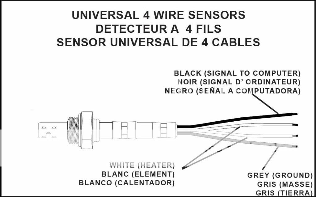
The wire colors used in the Bosch 4 Wire O2 Sensor Wiring Diagram are critical for ensuring that the sensor is properly connected to the engine management system. Each wire has a specific function, and the colors are used to identify the wires and ensure that they are connected correctly. The wire colors are typically standardized across different manufacturers, making it easier to identify and connect the wires.
For example, in the Bosch 4 Wire O2 Sensor Wiring Diagram, the black wire is typically used for ground, the white wire is typically used for signal, the gray wire is typically used for heater power, and the blue wire is typically used for heater ground. By following the wire colors, it is possible to ensure that the sensor is connected correctly and that it is functioning properly.
Real-life examples of the Bosch 4 Wire O2 Sensor Wiring Diagram can be found in a wide variety of vehicles. Some of the most common applications include:
- Passenger cars
- Light trucks
- SUVs
- Motorcycles
- Marine engines
The practical applications of understanding the relationship between the wire colors and the Bosch 4 Wire O2 Sensor Wiring Diagram are numerous. For example, this understanding can be used to:
- Troubleshoot problems with the oxygen sensor
- Install an oxygen sensor in a new vehicle
- Upgrade the oxygen sensor in an existing vehicle
Overall, the wire colors are a critical component of the Bosch 4 Wire O2 Sensor Wiring Diagram. By understanding the relationship between the wire colors and the wiring diagram, you can ensure that the sensor is properly installed and functioning correctly.
Pin assignments
Pin assignments are a critical component of the Bosch 4 Wire O2 Sensor Wiring Diagram. They determine which wires are connected to which pins on the connector, and this in turn determines how the sensor is connected to the engine management system. If the pin assignments are incorrect, the sensor will not be able to function properly.
For example, in the Bosch 4 Wire O2 Sensor Wiring Diagram, the black wire is typically connected to pin 1, the white wire is typically connected to pin 2, the gray wire is typically connected to pin 3, and the blue wire is typically connected to pin 4. This is the standard pin assignment for Bosch 4-wire oxygen sensors, and it is important to follow this standard when connecting the sensor to the engine management system.
Real-life examples of the Bosch 4 Wire O2 Sensor Wiring Diagram can be found in a wide variety of vehicles. Some of the most common applications include:
- Passenger cars
- Light trucks
- SUVs
- Motorcycles
- Marine engines
The practical applications of understanding the relationship between pin assignments and the Bosch 4 Wire O2 Sensor Wiring Diagram are numerous. For example, this understanding can be used to:
- Troubleshoot problems with the oxygen sensor
- Install an oxygen sensor in a new vehicle
- Upgrade the oxygen sensor in an existing vehicle
Overall, pin assignments are a critical component of the Bosch 4 Wire O2 Sensor Wiring Diagram. By understanding the relationship between pin assignments and the wiring diagram, you can ensure that the sensor is properly installed and functioning correctly.
Ground connection
In the Bosch 4 Wire O2 Sensor Wiring Diagram, the ground connection is a critical component that provides a reference point for the sensor’s electrical circuit. Without a proper ground connection, the sensor will not be able to function correctly and may provide inaccurate readings to the engine management system. The ground connection is typically made to the chassis of the vehicle or to a dedicated ground point on the engine.
The location of the ground connection is important because it affects the accuracy and stability of the sensor’s readings. If the ground connection is made to a point on the chassis that is subject to corrosion or vibration, the sensor’s readings may be erratic or unreliable. It is therefore important to choose a ground connection point that is clean, secure, and free from corrosion.
Real-life examples of the ground connection in the Bosch 4 Wire O2 Sensor Wiring Diagram can be found in a wide variety of vehicles. Some of the most common applications include:
- Passenger cars
- Light trucks
- SUVs
- Motorcycles
- Marine engines
The practical applications of understanding the relationship between the ground connection and the Bosch 4 Wire O2 Sensor Wiring Diagram are numerous. For example, this understanding can be used to:
- Troubleshoot problems with the oxygen sensor
- Install an oxygen sensor in a new vehicle
- Upgrade the oxygen sensor in an existing vehicle
In summary, the ground connection is a critical component of the Bosch 4 Wire O2 Sensor Wiring Diagram. It provides a reference point for the sensor’s electrical circuit and ensures that the sensor is able to provide accurate and stable readings to the engine management system. By understanding the importance of the ground connection and choosing a suitable location for it, you can ensure that the oxygen sensor is functioning correctly and providing accurate readings to the engine management system.
Heater circuit
In the Bosch 4 Wire O2 Sensor Wiring Diagram, the heater circuit is a critical component that provides power to the sensor’s heating element. The heating element is responsible for raising the sensor’s temperature to its optimal operating range, which is typically between 300C and 400C. Without a properly functioning heater circuit, the sensor will not be able to reach its optimal operating temperature and may provide inaccurate readings to the engine management system.
The heater circuit is typically powered by a 12-volt battery and is controlled by the engine management system. The engine management system will turn on the heater circuit when the engine is started and will turn it off when the engine is turned off. The heater circuit is also typically equipped with a fuse to protect it from damage in the event of a short circuit.
Real-life examples of the heater circuit in the Bosch 4 Wire O2 Sensor Wiring Diagram can be found in a wide variety of vehicles. Some of the most common applications include:
- Passenger cars
- Light trucks
- SUVs
- Motorcycles
- Marine engines
The practical applications of understanding the relationship between the heater circuit and the Bosch 4 Wire O2 Sensor Wiring Diagram are numerous. For example, this understanding can be used to:
- Troubleshoot problems with the oxygen sensor
- Install an oxygen sensor in a new vehicle
- Upgrade the oxygen sensor in an existing vehicle
In summary, the heater circuit is a critical component of the Bosch 4 Wire O2 Sensor Wiring Diagram. It provides power to the sensor’s heating element and ensures that the sensor is able to reach its optimal operating temperature. By understanding the importance of the heater circuit and how it works, you can ensure that the oxygen sensor is functioning correctly and providing accurate readings to the engine management system.
Signal circuit
In the Bosch 4 Wire O2 Sensor Wiring Diagram, the signal circuit is a critical component that carries the sensor’s output signal to the engine management system. This signal is used by the engine management system to determine the air-fuel ratio and to adjust the fuel injection accordingly. A properly functioning signal circuit is therefore essential for the proper operation of the engine.
- Signal wire: The signal wire is the wire that carries the sensor’s output signal to the engine management system. It is typically a shielded wire to protect the signal from interference.
- Signal conditioning circuit: The signal conditioning circuit is a circuit that prepares the sensor’s output signal for use by the engine management system. It may include components such as amplifiers, filters, and voltage regulators.
- Analog-to-digital converter (ADC): The ADC is a circuit that converts the sensor’s analog output signal into a digital signal that can be processed by the engine management system.
- Engine management system: The engine management system is the computer that controls the engine’s operation. It uses the sensor’s signal to determine the air-fuel ratio and to adjust the fuel injection accordingly.
The signal circuit is a critical component of the Bosch 4 Wire O2 Sensor Wiring Diagram. It ensures that the sensor’s output signal is accurately transmitted to the engine management system, which is essential for the proper operation of the engine. A malfunctioning signal circuit can lead to a variety of problems, including poor engine performance, increased emissions, and decreased fuel economy.
Calibration data
Calibration data is a critical component of the Bosch 4 Wire O2 Sensor Wiring Diagram. It is the data that is used to calibrate the sensor so that it can accurately measure the oxygen content of the exhaust gas. Without calibration data, the sensor would not be able to provide accurate readings to the engine management system. This could lead to a variety of problems, including poor engine performance, increased emissions, and decreased fuel economy.
The calibration data is typically stored in the sensor’s memory. When the sensor is connected to the engine management system, the engine management system will read the calibration data and use it to calibrate the sensor. The calibration data may also be stored in the engine management system itself. In this case, the engine management system will use the calibration data to calibrate the sensor when it is first connected to the vehicle.
Real-life examples of calibration data in the Bosch 4 Wire O2 Sensor Wiring Diagram can be found in a wide variety of vehicles. Some of the most common applications include:
- Passenger cars
- Light trucks
- SUVs
- Motorcycles
- Marine engines
The practical applications of understanding the relationship between calibration data and the Bosch 4 Wire O2 Sensor Wiring Diagram are numerous. For example, this understanding can be used to:
- Troubleshoot problems with the oxygen sensor
- Install an oxygen sensor in a new vehicle
- Upgrade the oxygen sensor in an existing vehicle
In summary, calibration data is a critical component of the Bosch 4 Wire O2 Sensor Wiring Diagram. It is the data that is used to calibrate the sensor so that it can accurately measure the oxygen content of the exhaust gas. By understanding the importance of calibration data and how it is used, you can ensure that the oxygen sensor is functioning correctly and providing accurate readings to the engine management system.
Diagnostic procedures
Diagnostic procedures are an essential component of the Bosch 4 Wire O2 Sensor Wiring Diagram as they provide a systematic approach to identifying and resolving issues with the sensor. These procedures involve using specialized tools and techniques to assess the sensor’s performance and identify any potential malfunctions. By understanding the diagnostic procedures and their relationship with the wiring diagram, technicians can effectively troubleshoot and repair the sensor, ensuring accurate readings and optimal engine performance.
Real-life examples of diagnostic procedures within the Bosch 4 Wire O2 Sensor Wiring Diagram include using a multimeter to measure voltage and resistance values at specific points in the circuit. By comparing the measured values to known specifications, technicians can identify any deviations that may indicate a faulty sensor or wiring issue. Additionally, using a scan tool to retrieve diagnostic trouble codes (DTCs) can provide valuable insights into the sensor’s operation and potential problems.
The practical applications of understanding the relationship between diagnostic procedures and the Bosch 4 Wire O2 Sensor Wiring Diagram are numerous. For instance, it enables technicians to:
- Quickly identify and resolve sensor malfunctions, reducing downtime and repair costs.
- Ensure accurate sensor readings, which are critical for maintaining optimal air-fuel ratios and engine performance.
- Prevent costly engine damage that may result from prolonged operation with a faulty oxygen sensor.


![[DIAGRAM] Bosch O2 Sensor Wiring Diagram](https://i0.wp.com/wikilec.com/images/9/94/EMJ4_Code_13_-_O2_sensor.gif?w=665&ssl=1)
![[DIAGRAM] Bosch 4 Wire 02 Sensor Diagram](https://i0.wp.com/repairguide.autozone.com/znetrgs/repair_guide_content/en_us/images/0996b43f/80/22/0d/0b/medium/0996b43f80220d0b.gif?w=665&ssl=1)


Related Posts


