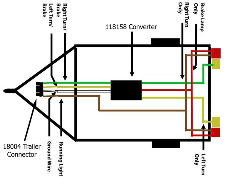
A Boat Trailer Wiring Diagram 4 Pin is a schematic representation of the electrical connections for a boat trailer that utilizes a 4-pin connector. It provides a standardized layout for wiring the trailer’s lighting system, ensuring proper functioning and safety during towing.
This wiring diagram outlines the specific wire colors and terminals designated for each function: ground, left turn signal, taillights, and right turn signal. By adhering to this standard, boat owners can confidently connect their trailer’s lights to the towing vehicle, facilitating clear communication between the two.
Understanding and utilizing this wiring diagram is crucial for safe and compliant towing practices. It ensures proper lighting for the trailer, preventing accidents and maintaining visibility on the road. Historically, the development of standardized wiring diagrams for boat trailers has significantly improved the ease and reliability of towing, enhancing safety and convenience.
Boat Trailer Wiring Diagram 4 Pin: Essential Aspects
- Standardization: A uniform framework for wiring boat trailers, ensuring compatibility and safety.
- Electrical Connections: Outlines the specific wire colors and terminals for ground, turn signals, and taillights.
- Lighting Functionality: Guides the proper wiring to ensure clear and visible lighting for the trailer.
- Safety and Compliance: Adhering to the diagram meets legal requirements and promotes safe towing practices.
- Color Coding: Facilitates quick and accurate identification of wire functions, simplifying installation.
- Grounding: Establishes a proper electrical path to prevent electrical issues and hazards.
- Turn Signal Synchronization: Ensures coordinated turn signal operation between the towing vehicle and trailer.
- Taillight Brightness: Specifies the wiring for optimal taillight visibility, enhancing safety on the road.
- Compatibility: Designed to be compatible with various towing vehicles and boat trailers, ensuring versatility.
These aspects are crucial for understanding and utilizing Boat Trailer Wiring Diagrams 4 Pin effectively. By considering these elements, boat owners can ensure proper lighting, electrical safety, and compliance with towing regulations. Furthermore, the standardization provided by these diagrams simplifies the installation and maintenance of boat trailer wiring systems, contributing to a safe and enjoyable towing experience.
Standardization
Within the context of “Boat Trailer Wiring Diagram 4 Pin”, standardization plays a pivotal role in establishing a uniform framework for wiring boat trailers, thereby ensuring compatibility and safety. This standardization encompasses various aspects, each contributing to the overall effectiveness and reliability of boat trailer wiring systems.
- Universal Compatibility: Standardized wiring diagrams guarantee seamless compatibility between boat trailers and towing vehicles, regardless of their respective manufacturers. This interchangeability simplifies the towing process and eliminates the need for custom wiring solutions.
- Simplified Installation: Adhering to standardized diagrams simplifies the installation process, making it accessible to individuals with varying levels of electrical expertise. Clear instructions and color-coded wires facilitate quick and accurate connections.
- Enhanced Safety: Standardization ensures that all boat trailers are wired consistently, promoting uniformity in lighting functions. This consistency enhances safety on the road, as other drivers can easily recognize and anticipate the actions of a towing vehicle and its trailer.
- Legal Compliance: Many regions have specific regulations governing the wiring of boat trailers. Standardized diagrams help ensure compliance with these regulations, mitigating legal liabilities and promoting safe towing practices.
Overall, the standardization of boat trailer wiring diagrams through the “Boat Trailer Wiring Diagram 4 Pin” system is a critical factor in ensuring compatibility, safety, and ease of installation. By adhering to these standards, boat owners can confidently tow their trailers, knowing that their lighting systems are functioning properly and meeting regulatory requirements.
Electrical Connections
Within the context of “Boat Trailer Wiring Diagram 4 Pin”, the aspect of “Electrical Connections: Outlines the specific wire colors and terminals for ground, turn signals, and taillights” holds immense significance. It establishes a standardized framework for wiring these essential components, ensuring proper functionality, safety, and compliance with regulations.
- Color-Coded Wires: Standardized wiring diagrams assign specific colors to different functions, simplifying identification and installation. For instance, brown wires typically denote taillights, green wires represent right turn signals, and yellow wires indicate left turn signals.
- Terminal Designations: Diagrams clearly indicate the designated terminals for each wire, ensuring proper connections. This eliminates guesswork and reduces the risk of incorrect wiring, which could lead to electrical issues or malfunctioning lights.
- Grounding: Proper grounding is crucial for electrical safety. Diagrams specify the terminal and wire color designated for grounding, ensuring a secure connection to the trailer’s frame.
- Compatibility: Standardized electrical connections facilitate compatibility between boat trailers and various towing vehicles. By adhering to these standards, boat owners can confidently connect their trailers to different vehicles without compatibility concerns.
Overall, the “Electrical Connections: Outlines the specific wire colors and terminals for ground, turn signals, and taillights” aspect of “Boat Trailer Wiring Diagram 4 Pin” ensures that boat trailers are wired correctly and safely. It promotes standardized practices, simplifies installation and maintenance, and enhances the reliability and longevity of trailer lighting systems.
Lighting Functionality
Within the context of “Boat Trailer Wiring Diagram 4 Pin”, the aspect of “Lighting Functionality: Guides the proper wiring to ensure clear and visible lighting for the trailer” stands as a cornerstone for safe and compliant towing. It encompasses the specific wiring configurations and components necessary to ensure that the trailer’s lighting system operates effectively, enabling clear visibility and communication on the road.
- Taillight Brightness: The wiring diagram specifies the proper gauge and length of wires to ensure adequate power supply to the taillights, guaranteeing their visibility even in adverse weather conditions.
- Turn Signal Synchronization: Clear and synchronized turn signals are crucial for safe towing. The diagram outlines the wiring connections for both left and right turn signals, ensuring that they flash in unison with the towing vehicle.
- Reflective Components: The diagram may include recommendations for incorporating reflective elements into the trailer’s lighting system. These reflective surfaces enhance visibility, making the trailer more noticeable to other vehicles, especially at night.
- Compatibility with LED Lights: Modern boat trailers often utilize LED lighting systems. The wiring diagram provides guidance on the appropriate wiring modifications and considerations for compatibility with LED lights, ensuring optimal performance and longevity.
Overall, the “Lighting Functionality: Guides the proper wiring to ensure clear and visible lighting for the trailer” aspect of “Boat Trailer Wiring Diagram 4 Pin” plays a pivotal role in ensuring the safety and visibility of boat trailers on the road. By adhering to these guidelines, boat owners can confidently tow their trailers, knowing that their lighting systems are functioning properly, meeting regulatory requirements, and enhancing the visibility of their trailers to other motorists.
Safety and Compliance
Within the context of “Boat Trailer Wiring Diagram 4 Pin”, the aspect of “Safety and Compliance: Adhering to the diagram meets legal requirements and promotes safe towing practices” takes center stage, underscoring the paramount importance of following standardized wiring guidelines to ensure the safety and legality of boat trailer operations. This encompasses various facets, each contributing to the overall well-being of boaters, other motorists, and the environment.
- Legal Compliance: Adhering to the wiring diagram ensures compliance with local and national regulations governing the electrical systems of boat trailers. This compliance mitigates legal liabilities and fines, fostering a culture of responsible trailering practices.
- Safe Lighting: The diagram guides the proper wiring of lighting components, including taillights, turn signals, and brake lights. Properly functioning lights enhance visibility, enabling other drivers to clearly see the trailer’s movements and intentions, thereby reducing the risk of accidents.
- Electrical Safety: The diagram specifies the appropriate wire gauges and connections to prevent electrical hazards. By following these guidelines, boat owners can minimize the risk of electrical fires, shorts, or malfunctions, ensuring the safety of the trailer and its occupants.
- Environmental Protection: Correct wiring practices help prevent electrical issues that could lead to fluid leaks or battery damage. This proactive approach safeguards the environment from potential contamination, promoting sustainable trailering practices.
In conclusion, the “Safety and Compliance: Adhering to the diagram meets legal requirements and promotes safe towing practices” aspect of “Boat Trailer Wiring Diagram 4 Pin” serves as a cornerstone for responsible and safe trailering. By adhering to these guidelines, boat owners can confidently tow their trailers, knowing that their lighting systems are compliant, visible, and electrically sound, contributing to the safety and well-being of all road users and the environment.
Color Coding
Within the context of “Boat Trailer Wiring Diagram 4 Pin”, the utilization of color coding plays a pivotal role in streamlining the installation and maintenance processes, making it a critical component of the overall wiring system.
Color coding involves assigning specific colors to different wire functions, enabling quick and accurate identification during installation. This standardized approach eliminates guesswork and reduces the likelihood of incorrect connections, which could lead to electrical issues or malfunctioning lights.
For instance, in a typical “Boat Trailer Wiring Diagram 4 Pin”, the brown wire is designated for taillights, the green wire represents the right turn signal, and the yellow wire indicates the left turn signal. This color coding corresponds with the color coding typically found on the towing vehicle, ensuring seamless and intuitive connections.
The practical significance of color coding extends beyond simplified installation. It also facilitates troubleshooting and maintenance. By easily identifying the function of each wire based on its color, boat owners can quickly diagnose and resolve any electrical issues that may arise.
Moreover, color coding promotes consistency and standardization across different boat trailer models and manufacturers. This consistency enables boat owners and technicians to work on unfamiliar trailers with greater ease and confidence, knowing that the color coding will be consistent.
In conclusion, the use of color coding in “Boat Trailer Wiring Diagram 4 Pin” is a critical factor in ensuring efficient installation, simplified maintenance, and enhanced safety. By adhering to standardized color-coding practices, boat owners can confidently wire their trailers, ensuring proper functionality and compliance with regulations.
Grounding
Within the context of “Boat Trailer Wiring Diagram 4 Pin”, grounding plays a pivotal role in ensuring the safety and reliability of the electrical system. Grounding establishes a proper electrical path, providing a safe and controlled pathway for the flow of electrical current, thereby preventing electrical issues and hazards.
The absence of proper grounding can lead to a range of electrical problems, including short circuits, electrical fires, and equipment damage. In the context of boat trailer wiring, grounding serves as the foundation for a stable and functional electrical system.
A real-life example of grounding in “Boat Trailer Wiring Diagram 4 Pin” is the connection of the trailer’s frame to the negative terminal of the battery. This connection provides a low-resistance path for electrical current to return to the power source, ensuring the proper functioning of lights, turn signals, and other electrical components.
Practically, understanding the importance of grounding in “Boat Trailer Wiring Diagram 4 Pin” enables boat owners and technicians to troubleshoot and resolve electrical issues more effectively. By ensuring proper grounding, they can prevent electrical hazards, extend the lifespan of electrical components, and maintain the safety and reliability of their boat trailers.
In summary, grounding is a critical component of “Boat Trailer Wiring Diagram 4 Pin” as it establishes a safe electrical path, preventing electrical issues and hazards. Understanding the significance of grounding empowers boat owners and technicians to maintain and operate their boat trailers safely and efficiently.
Turn Signal Synchronization
Within the context of “Boat Trailer Wiring Diagram 4 Pin,” turn signal synchronization is a critical component that ensures the coordinated operation of turn signals between the towing vehicle and the trailer. This synchronization is vital for safe and effective communication on the road.
The “Boat Trailer Wiring Diagram 4 Pin” provides the framework for connecting the electrical systems of the towing vehicle and the trailer, including the turn signals. By following the diagram and utilizing the designated wire colors, boat owners can establish a reliable electrical connection that enables synchronized turn signal operation.
A real-life example of turn signal synchronization in “Boat Trailer Wiring Diagram 4 Pin” is the connection of the green wire from the towing vehicle to the green wire on the trailer. This connection ensures that when the turn signal is activated on the towing vehicle, the corresponding turn signal on the trailer will illuminate simultaneously.
Practically, understanding turn signal synchronization in “Boat Trailer Wiring Diagram 4 Pin” empowers boat owners with the knowledge to troubleshoot and resolve electrical issues related to turn signals. By ensuring proper synchronization, they can enhance the safety and visibility of their boat trailers on the road.
In summary, turn signal synchronization in “Boat Trailer Wiring Diagram 4 Pin” is crucial for safe and effective towing practices. It enables coordinated turn signal operation, enhances communication on the road, and empowers boat owners to maintain and operate their boat trailers with confidence.
Taillight Brightness
Within the context of “Boat Trailer Wiring Diagram 4 Pin,” taillight brightness holds paramount importance in ensuring the safety and visibility of boat trailers on the road. The diagram specifies the proper wiring configurations and components to achieve optimal taillight brightness, enabling clear communication and reducing the risk of rear-end collisions.
- Adequate Wiring Gauge: The diagram specifies the appropriate wire gauge for the taillights, ensuring sufficient current flow to maintain optimal brightness. Insufficient wire gauge can lead to voltage drop and dim taillights, compromising visibility.
- Proper Grounding: A secure electrical ground connection is crucial for proper taillight brightness. The diagram outlines the designated grounding point, ensuring a complete circuit and preventing potential voltage fluctuations that could affect taillight output.
- Reflective Surfaces: The diagram may include recommendations for incorporating reflective surfaces around the taillights. These reflective surfaces enhance the visibility of the trailer, especially at night or in low-light conditions, further increasing safety.
- LED Lighting Compatibility: Modern boat trailers often utilize LED taillights. The wiring diagram provides guidance on the appropriate wiring modifications and considerations for compatibility with LED lights, ensuring optimal brightness and longevity.
By adhering to the “Taillight Brightness: Specifies the wiring for optimal taillight visibility, enhancing safety on the road” aspect of “Boat Trailer Wiring Diagram 4 Pin,” boat owners can confidently tow their trailers, knowing that their taillights are functioning at maximum brightness. This contributes to enhanced visibility, safer nighttime towing, and reduced risk of accidents on the road.
Compatibility
Within the context of “Boat Trailer Wiring Diagram 4 Pin,” compatibility plays a crucial role in ensuring that boat trailers can be safely and effectively towed by a wide range of towing vehicles. The “Compatibility: Designed to be compatible with various towing vehicles and boat trailers, ensuring versatility” aspect of the diagram addresses this need, providing guidelines and specifications to achieve seamless connectivity and functionality.
- Universal Connectors: The diagram employs standardized connectors that are compatible with most towing vehicles and boat trailers. These connectors feature a universal design that allows for easy and secure connections, regardless of the specific makes and models involved.
- Wire Gauge and Length: The diagram specifies the appropriate wire gauge and length for each connection, ensuring that the electrical system can handle the required current and voltage. This compatibility ensures optimal performance and prevents potential issues such as overheating or voltage drop.
- LED Compatibility: Modern boat trailers often utilize LED lighting systems. The wiring diagram provides guidance on the appropriate wiring modifications and considerations for compatibility with LED lights, ensuring that these energy-efficient and long-lasting lights can be integrated seamlessly.
- Grounding Compatibility: Proper grounding is essential for electrical safety and functionality. The diagram outlines the designated grounding points and ensures compatibility with various boat trailer frames and towing vehicle grounding systems, promoting safe and reliable electrical connections.
By adhering to the “Compatibility: Designed to be compatible with various towing vehicles and boat trailers, ensuring versatility” aspect of “Boat Trailer Wiring Diagram 4 Pin,” boat owners can confidently tow their trailers, knowing that their electrical systems are compatible, functional, and compliant with industry standards. This compatibility ensures safe and reliable towing experiences, regardless of the specific equipment being used.


Related Posts


