A boat fuel gauge wiring diagram is a schematic representation of the electrical wiring involved in connecting a fuel gauge to a boat’s fuel tank. It outlines the connections between the gauge, the fuel tank, the power source, and any additional components such as resistors or switches.
A wiring diagram is crucial for ensuring the accurate and reliable operation of the fuel gauge. It minimizes the risk of electrical faults or misconnections, which can lead to incorrect readings or even safety hazards. The availability of the diagram makes it easier to troubleshoot and maintain the fuel gauge system, saving time and reducing the chance of costly repairs.
Historically, boat fuel gauge wiring diagrams have been drawn by hand or created using basic software. With technological advancements, computer-aided design (CAD) software is increasingly used to create detailed and accurate diagrams that simplify the installation and maintenance process.
In the following sections, we will further explore the uses and benefits of boat fuel gauge wiring diagrams as well as delve into the components and connections they typically include.
Understanding the essential aspects of a boat fuel gauge wiring diagram is crucial for ensuring the accurate and reliable operation of the fuel gauge system. These aspects encompass various dimensions, ranging from the components involved to the connections and the overall functionality of the diagram.
- Components
- Connections
- Functionality
- Accuracy
- Reliability
- Troubleshooting
- Maintenance
- Safety
- Compliance
- Customization
These aspects are interconnected and contribute to the overall effectiveness of the fuel gauge wiring diagram. For instance, the accuracy and reliability of the diagram depend on the quality of the components used and the correctness of the connections. Proper troubleshooting and maintenance procedures ensure that the diagram continues to function as intended, while compliance with industry standards and regulations enhances safety and reliability. Additionally, customization options allow boat owners to tailor the diagram to their specific needs and preferences.
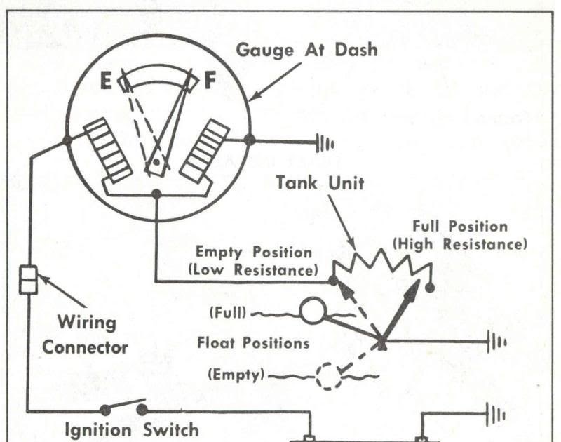
Components
In the context of boat fuel gauge wiring diagrams, components refer to the individual electrical and electronic elements that constitute the system. These components play critical roles in ensuring the accurate and reliable operation of the fuel gauge, providing essential functions such as sensing, transmitting, and displaying fuel level information.
The selection and arrangement of components in a boat fuel gauge wiring diagram depend on the specific design and requirements of the system. Common components include:
- Fuel tank sender: A sensor installed inside the fuel tank that measures the fuel level and transmits the information as an electrical signal.
- Fuel gauge: A display unit that receives the electrical signal from the fuel tank sender and translates it into a visual representation of the fuel level.
- Wiring: Electrical wires and connectors that establish the electrical connections between the fuel tank sender, fuel gauge, and other components.
- Resistors: Electrical components that regulate the flow of current in the circuit, ensuring accurate readings from the fuel tank sender.
- Power source: Typically the boat’s electrical system, which provides the necessary power to operate the fuel gauge and its components.
Understanding the relationship between components and boat fuel gauge wiring diagrams is crucial for several reasons. First, it enables technicians and boat owners to troubleshoot and repair fuel gauge systems effectively. By identifying and understanding the function of each component, they can pinpoint the source of any problems and implement appropriate solutions.
Additionally, this understanding allows for customization and optimization of fuel gauge systems. By selecting and arranging components carefully, boat owners can tailor their systems to specific needs, such as integrating digital displays, alarms, or remote monitoring capabilities.
Connections
In the context of boat fuel gauge wiring diagrams, connections refer to the electrical pathways established between the various components of the fuel gauge system. These connections serve as the foundation for the accurate and reliable transmission of information about fuel levels.
- Electrical Wires: The backbone of connections, electrical wires are responsible for carrying electrical signals between components. Proper insulation and gauge selection are crucial for ensuring signal integrity and minimizing voltage drop.
- Connectors: Connectors provide a secure and reliable means of joining electrical wires. They prevent accidental disconnections and ensure a consistent electrical connection over time.
- Terminal Blocks: Terminal blocks provide a convenient and organized way to connect multiple wires. They allow for easy troubleshooting and maintenance of the wiring system.
- Grounding: Proper grounding is essential for the safety and accuracy of the fuel gauge system. It provides a reference point for electrical signals and prevents electrical noise and interference.
Understanding the types, functions, and implications of connections is crucial for the effective installation, troubleshooting, and maintenance of boat fuel gauge wiring diagrams. By paying attention to the quality and reliability of connections, boat owners and technicians can ensure that the fuel gauge system operates accurately and reliably, providing critical information about fuel levels at all times.
Functionality
In the context of boat fuel gauge wiring diagrams, functionality refers to the ability of the system to accurately measure and display fuel levels. This functionality is critical for ensuring that boat operators have the necessary information to make informed decisions regarding fuel management and navigation. A properly functioning fuel gauge system provides peace of mind, allowing boaters to confidently plan their trips and avoid running out of fuel.
The functionality of a boat fuel gauge wiring diagram is dependent on the proper installation, configuration, and maintenance of its components. This includes selecting the correct components for the specific fuel tank and gauge, ensuring secure and reliable connections, and following manufacturer guidelines for installation and calibration. A well-designed and executed wiring diagram will result in a fuel gauge system that provides accurate and consistent readings.
Understanding the relationship between functionality and boat fuel gauge wiring diagrams is essential for boat owners and technicians alike. By paying attention to the details of the wiring diagram and ensuring proper installation and maintenance, boaters can ensure that their fuel gauge systems are functioning optimally. This understanding also allows for troubleshooting and repair in the event of any issues, ensuring that the system continues to provide reliable fuel level information.
Accuracy
Within the context of boat fuel gauge wiring diagrams, accuracy refers to the extent to which the fuel gauge readings correspond to the actual fuel level in the tank. A highly accurate fuel gauge system provides boaters with a reliable indication of their fuel status, enabling them to make informed decisions about refueling and trip planning.
- Calibration: The process of adjusting the fuel gauge to accurately reflect the fuel tank’s capacity and shape. Proper calibration ensures that the gauge readings are consistent and reliable across the entire fuel level range.
- Component Quality: The quality of the components used in the fuel gauge system, including the fuel tank sender, fuel gauge, and wiring, directly impacts accuracy. High-quality components are less prone to failure and provide more consistent readings over time.
- Electrical Interference: Electrical noise and interference from other devices on the boat can affect the accuracy of the fuel gauge readings. Proper grounding and shielding techniques are crucial to minimize interference and ensure reliable operation.
- Environmental Conditions: Factors such as temperature, vibration, and humidity can influence the accuracy of the fuel gauge system. Ensuring that the components are rated for the specific environmental conditions on the boat is essential for maintaining accuracy.
Accuracy in boat fuel gauge wiring diagrams is critical for several reasons. It allows boaters to accurately gauge their fuel consumption, plan their trips accordingly, and avoid running out of fuel unexpectedly. Additionally, accurate fuel gauge readings are important for monitoring fuel usage and detecting potential fuel leaks or discrepancies. By understanding the factors that affect accuracy and implementing appropriate measures, boat owners can ensure that their fuel gauge systems provide reliable and accurate information.
Reliability
In the context of boat fuel gauge wiring diagrams, reliability refers to the ability of the system to consistently provide accurate and dependable fuel level readings. A reliable fuel gauge system is crucial for ensuring the safety and peace of mind of boaters, as it allows them to make informed decisions about refueling and trip planning.
- Component Quality: High-quality components, such as a durable fuel tank sender and a robust fuel gauge, are less prone to failure and provide more consistent readings over an extended period. This reduces the likelihood of sudden or unexpected malfunctions.
- Electrical Stability: A stable electrical system on the boat minimizes the risk of voltage fluctuations or electrical interference, which can affect the accuracy of the fuel gauge readings. Proper grounding and shielding techniques help ensure a reliable electrical environment for the fuel gauge system.
- Environmental Resilience: Fuel gauge components should be rated for the specific environmental conditions on the boat, including exposure to moisture, vibration, and temperature extremes. This ensures that the system continues to function reliably even in harsh marine environments.
- Redundancy: Incorporating redundancy into the fuel gauge system, such as having a backup fuel gauge or a manual fuel level indicator, can enhance reliability. Redundant components provide a failsafe mechanism in case of a primary component failure, ensuring that boaters have access to critical fuel level information.
Reliability in boat fuel gauge wiring diagrams is paramount for safe and enjoyable boating experiences. By understanding and addressing the factors that contribute to reliability, boat owners and technicians can implement measures to minimize the risk of fuel gauge malfunctions and ensure that their systems provide accurate and dependable information at all times.
Troubleshooting
Troubleshooting is a critical aspect of boat fuel gauge wiring diagrams, as it enables boat owners and technicians to identify and resolve issues that may affect the accuracy or reliability of the fuel gauge system. Without proper troubleshooting procedures, it can be challenging to pinpoint the root cause of a malfunctioning fuel gauge, leading to frustration and potential safety concerns.
The relationship between troubleshooting and boat fuel gauge wiring diagrams is bidirectional. On the one hand, a well-designed wiring diagram provides a structured framework for troubleshooting, as it outlines the connections and components of the fuel gauge system. This allows technicians to systematically check each component and connection, identifying potential points of failure or incorrect wiring.
On the other hand, effective troubleshooting can uncover errors or inconsistencies in the wiring diagram itself. For instance, if the troubleshooting process reveals that the fuel gauge is not receiving power, the wiring diagram may need to be revised to include a missing power connection. By iteratively troubleshooting and refining the wiring diagram, boat owners and technicians can ensure that it accurately reflects the actual system and facilitates future troubleshooting efforts.
In practical terms, troubleshooting a boat fuel gauge wiring diagram involves using a multimeter to measure voltage and continuity at various points in the circuit. This allows technicians to identify open circuits, short circuits, or faulty components. Additionally, visual inspection of the wiring and connections can reveal loose or damaged wires, corrosion, or other issues that may affect the system’s performance.
Maintenance
Maintenance plays a pivotal role in the accuracy, reliability, and longevity of boat fuel gauge wiring diagrams. Regular maintenance helps prevent issues, identify potential problems early on, and ensure the system continues to function as intended.
One of the critical aspects of maintenance is periodic inspection of the wiring and connections. Loose or damaged wires, corrosion, and other issues can affect the accuracy of the fuel gauge readings. By visually inspecting the system and addressing any issues promptly, boat owners can minimize the risk of malfunctions and ensure the wiring diagram remains accurate and reliable.
Another essential maintenance task is regular calibration of the fuel gauge. Over time, the fuel tank may change shape or the fuel gauge itself may become less accurate. Calibration involves adjusting the fuel gauge to ensure that it accurately reflects the actual fuel level in the tank. Proper calibration is crucial for ensuring that boaters have accurate information about their fuel status, allowing them to make informed decisions about refueling and trip planning.
Understanding the connection between maintenance and boat fuel gauge wiring diagrams empowers boat owners and technicians to maintain the accuracy and reliability of their fuel gauge systems. By implementing regular maintenance procedures and addressing issues promptly, they can prevent costly repairs or even dangerous situations that could arise from incorrect fuel level readings.
Safety
Within the context of boat fuel gauge wiring diagrams, safety takes paramount importance, encompassing various aspects that ensure the well-being of boaters and the integrity of the vessel. Understanding and adhering to safety guidelines when working with these diagrams is crucial to prevent electrical hazards, fires, and other potential risks.
-
Proper Grounding:
Ensuring a proper electrical ground for the fuel gauge system is essential to prevent electrical shocks and fires. Grounding provides a safe path for electrical current to flow, reducing the risk of accidents.
-
Adequate Wiring:
Using wires with appropriate gauge and insulation is crucial for handling the electrical current safely. Undersized wires can overheat and pose fire hazards, while inadequate insulation can lead to electrical shorts.
-
Secure Connections:
All electrical connections should be properly secured using appropriate connectors and terminals. Loose connections can cause arcing, sparking, and potential fires.
-
Protection from Elements:
The wiring and components of the fuel gauge system should be protected from exposure to water, moisture, and harsh marine conditions. Corrosion or damage to electrical components can compromise safety and accuracy.
By considering these safety aspects and following industry-recommended practices when working with boat fuel gauge wiring diagrams, boat owners and technicians can minimize risks, ensure reliable operation, and contribute to the overall safety of their vessels.
Compliance
Compliance, in the context of boat fuel gauge wiring diagrams, plays a critical role in ensuring the safety, accuracy, and reliability of fuel gauge systems on boats. By adhering to industry standards and regulations, boat owners and technicians can minimize risks, prevent accidents, and maintain the integrity of their vessels.
One of the primary reasons for compliance is to ensure the accuracy of fuel gauge readings. Accurate fuel gauges are essential for boaters to make informed decisions about refueling and trip planning. Non-compliant wiring diagrams or improper installation can lead to inaccurate readings, which can have serious consequences, such as running out of fuel or overloading the fuel tank.
Compliance also encompasses the use of appropriate materials and components. For example, using marine-grade wiring and connectors ensures that the wiring diagram is resistant to corrosion and harsh marine environments. Non-compliant materials may deteriorate over time, leading to electrical faults or even fires.
Understanding the importance of compliance empowers boat owners and technicians to make informed decisions when working with boat fuel gauge wiring diagrams. By adhering to industry standards and best practices, they can contribute to the overall safety and reliability of their vessels, ensuring enjoyable and worry-free boating experiences.
Customization
Customization plays a significant role in tailoring boat fuel gauge wiring diagrams to specific needs and preferences, enhancing the functionality and user experience of the fuel gauge system. It involves modifying or adapting various components of the wiring diagram to suit different boat types, fuel tank configurations, and desired features.
-
Component Selection:
Boat owners can choose from a range of fuel tank senders, fuel gauges, and wiring components to match the specific characteristics of their boat and fuel tank. This includes selecting the appropriate sender unit for the fuel tank’s shape and capacity, and choosing a fuel gauge with the desired display and features. -
Circuit Modifications:
Customization allows for modifications to the wiring circuit to accommodate additional components or features. For instance, boat owners can incorporate a fuel management system to monitor fuel consumption and track fuel usage over time, or add an alarm system to warn of low fuel levels. -
Integration with Other Systems:
Wiring diagrams can be customized to integrate the fuel gauge system with other onboard systems. This includes connecting the fuel gauge to the boat’s navigation system to display fuel level information on the chartplotter or interfacing with engine control systems to adjust engine performance based on fuel availability. -
Aesthetic Customization:
In addition to functional modifications, customization can also extend to the aesthetic aspects of the wiring diagram. Boat owners can choose fuel gauges with different styles, colors, and display options to match the overall design and interior of their boat.
Customization of boat fuel gauge wiring diagrams empowers boat owners and technicians to create tailored systems that meet their unique requirements. By carefully considering the various facets of customization and implementing appropriate modifications, they can enhance the accuracy, reliability, and user-friendliness of their fuel gauge systems, ultimately contributing to a more enjoyable and safe boating experience.


Related Posts


