A Basic Car Battery Wiring Diagram illustrates the electrical connections between the battery, electrical components, and ground in a vehicle. It serves as a roadmap for understanding the electrical system, troubleshooting issues, and performing repairs or modifications.
The diagram is essential for understanding how electrical current flows through the vehicle, powering various systems such as lights, ignition, and sensors. It helps identify the proper connection points, wire types, and fuse ratings required for a safe and functional electrical system. Wiring diagrams have evolved over time, from simple sketches to complex computer-aided designs, aiding in the maintenance and advancement of automotive technology.
In this article, we willbasic car battery wiring diagrams, examining their components, symbols, and applications in greater detail, providing a comprehensive understanding of their role in vehicle electrical systems.
Understanding the essential aspects of a Basic Car Battery Wiring Diagram is crucial for comprehending the electrical system of a vehicle. These aspects encompass the diagram’s components, symbols, applications, and historical context, among others.
- Components: Battery, electrical components, ground connections, wires, and fuses.
- Symbols: Standardized graphical representations of electrical components and connections.
- Applications: Troubleshooting electrical issues, performing repairs and modifications, understanding electrical system operation.
- Historical Context: Evolution from simple sketches to computer-aided designs, reflecting advancements in automotive technology.
- Safety: Ensures proper connections, wire types, and fuse ratings for a safe electrical system.
- Circuit Protection: Identifies fuse locations and ratings, protecting electrical components from overcurrent.
- Grounding: Illustrates the connections between electrical components and the vehicle’s chassis, ensuring proper current flow.
- Power Distribution: Shows how electrical power is distributed from the battery to various vehicle systems.
- Troubleshooting: Guides the identification and resolution of electrical problems by tracing current flow and component connections.
These aspects collectively contribute to the comprehension and application of Basic Car Battery Wiring Diagrams. They provide a systematic framework for understanding the electrical system, enabling efficient troubleshooting, repairs, and modifications. Furthermore, they reflect the evolution and importance of electrical diagrams in the automotive industry.
Components
Delving into the fundamental components of a Basic Car Battery Wiring Diagram unveils the building blocks of a vehicle’s electrical system. These essential elements ensure the efficient flow of electrical current, powering various systems and enabling seamless operation.
- Battery: The heart of the electrical system, the battery stores chemical energy and converts it into electrical energy, providing power to start the engine and operate electrical components.
- Electrical components: Encompassing a wide range of devices such as lights, sensors, actuators, and control modules, electrical components consume electrical power to perform their designated functions, from illuminating the road to managing engine performance.
- Ground connections: Establishing a complete electrical circuit, ground connections provide a path for electrical current to return to the battery, completing the circuit and enabling proper functioning of electrical components.
- Wires: Acting as the pathways for electrical current flow, wires connect various electrical components and distribute power throughout the vehicle’s electrical system.
- Fuses: Serving as safety devices, fuses protect electrical components and wiring from damage caused by overcurrent, preventing electrical fires and ensuring system reliability.
Understanding the interplay between these components is crucial for comprehending the operation and maintenance of a vehicle’s electrical system. A Basic Car Battery Wiring Diagram serves as a visual representation of these components and their connections, providing a roadmap for troubleshooting, repairs, and modifications.
Symbols
Within the context of a Basic Car Battery Wiring Diagram, symbols play a critical role in conveying complex electrical information in a clear and concise manner. These standardized graphical representations serve as a universal language, enabling technicians and enthusiasts alike to decipher the intricacies of automotive electrical systems.
Electrical components, such as batteries, fuses, switches, and sensors, are denoted by unique symbols that accurately reflect their function and appearance. Wires, the pathways for electrical current flow, are represented by lines connecting these symbols. Ground connections, essential for completing electrical circuits, are indicated by specific symbols as well.
The use of standardized symbols in Basic Car Battery Wiring Diagrams offers several advantages. Firstly, it ensures consistency and clarity in electrical schematics, facilitating easy understanding and interpretation. Secondly, symbols transcend language barriers, allowing diagrams to be universally understood by individuals from different linguistic backgrounds.
To illustrate the practical significance of symbols in a Basic Car Battery Wiring Diagram, consider the following real-life example. A technician troubleshooting a faulty electrical component can refer to the diagram to identify the component’s symbol, trace its connections, and pinpoint the source of the issue. This systematic approach, guided by standardized symbols, significantly reduces diagnostic time and effort.
Furthermore, the understanding of symbols empowers individuals to perform basic electrical repairs and modifications on their vehicles. By deciphering the wiring diagram, they can identify faulty components, replace fuses, and even install additional electrical accessories.
In summary, symbols in Basic Car Battery Wiring Diagrams are indispensable for comprehending, troubleshooting, and modifying automotive electrical systems. Their standardized nature promotes clarity, transcends language barriers, and empowers individuals to maintain and enhance their vehicles’ electrical infrastructure.
Applications
Basic Car Battery Wiring Diagrams transcend their role as mere representations of electrical connections; they serve as practical tools with wide-ranging applications in the maintenance and enhancement of automotive electrical systems. These applications encompass troubleshooting electrical issues, performing repairs and modifications, and gaining a comprehensive understanding of the electrical system’s operation.
- Troubleshooting Electrical Issues: Wiring diagrams empower individuals to systematically diagnose electrical faults. By tracing the flow of current through the diagram, they can identify malfunctioning components, loose connections, or breaks in the wiring, leading to efficient problem resolution.
- Performing Repairs and Modifications: Diagrams provide a roadmap for performing electrical repairs, guiding the replacement of faulty components and the installation of additional electrical accessories. This enables enthusiasts to customize their vehicles’ electrical systems, enhancing functionality and aesthetics.
- Understanding Electrical System Operation: Wiring diagrams offer a comprehensive overview of the electrical system’s architecture and functionality. By studying the diagram, individuals can trace the power distribution from the battery to various electrical components, gaining insights into the system’s design and operation.
- Safety and Reliability: Accurate wiring diagrams promote electrical safety by ensuring proper connections and component ratings. They help avoid electrical fires, malfunctions, and other hazards, contributing to the overall reliability and longevity of the vehicle’s electrical system.
In conclusion, Basic Car Battery Wiring Diagrams are indispensable tools for troubleshooting, repairs, modifications, and understanding the electrical system. Their applications extend beyond mere visual representations, empowering individuals to maintain, enhance, and optimize their vehicles’ electrical infrastructure.
Historical Context
The evolution of Basic Car Battery Wiring Diagrams from simple sketches to computer-aided designs (CAD) is inextricably linked to the advancements in automotive technology. This historical context is a critical component in understanding the sophistication and accuracy of modern wiring diagrams.
In the early days of automobiles, electrical systems were relatively simple, with hand-drawn sketches serving as basic wiring diagrams. These sketches provided a rudimentary representation of the electrical connections, but their accuracy and detail were often limited. As automotive electrical systems grew more complex, the need for more precise and comprehensive wiring diagrams became apparent.
The advent of CAD revolutionized the creation of wiring diagrams. CAD software allows engineers to create highly detailed and accurate diagrams that precisely represent the electrical connections in a vehicle. These diagrams incorporate standardized symbols, color-coding, and other visual cues to enhance clarity and ease of understanding.
Modern Basic Car Battery Wiring Diagrams are essential tools for troubleshooting electrical issues, performing repairs and modifications, and understanding the operation of the electrical system. They provide a comprehensive overview of the electrical connections, enabling technicians and enthusiasts alike to diagnose problems, identify faulty components, and make informed decisions about electrical modifications.
The historical evolution of wiring diagrams from simple sketches to CAD reflects the increasing complexity and sophistication of automotive electrical systems. Modern wiring diagrams are indispensable tools that contribute to the safety, reliability, and performance of modern vehicles.
Safety
Within the context of a Basic Car Battery Wiring Diagram, safety takes paramount importance. The diagram ensures proper connections, appropriate wire types, and correct fuse ratings, all of which contribute to a safe and reliable electrical system. This aspect of the wiring diagram plays a pivotal role in preventing electrical fires, malfunctions, and other hazards.
-
Proper Connections:
Proper connections are vital for maintaining electrical integrity and preventing short circuits. The wiring diagram specifies the correct connection points and techniques, ensuring that components are securely fastened and insulated to avoid loose connections and arcing. -
Appropriate Wire Types:
Selecting the appropriate wire types is crucial for handling the electrical load and ensuring safe operation. The wiring diagram specifies the wire gauge, insulation type, and temperature rating for each circuit, ensuring that wires can carry the current without overheating or insulation breakdown. -
Correct Fuse Ratings:
Fuses are essential safety devices that protect electrical components and wiring from overcurrent conditions. The wiring diagram specifies the correct fuse rating for each circuit, ensuring that fuses will blow in the event of a fault, preventing damage to sensitive components. -
Grounding:
Proper grounding is essential for completing electrical circuits and preventing voltage spikes. The wiring diagram indicates the grounding points for various components, ensuring that electrical current has a safe path to return to the battery, minimizing the risk of electrical shock or damage.
In conclusion, the safety aspect of a Basic Car Battery Wiring Diagram is indispensable for maintaining a safe and reliable electrical system. By ensuring proper connections, appropriate wire types, correct fuse ratings, and proper grounding, the diagram contributes to the prevention of electrical hazards and ensures the longevity of the vehicle’s electrical components.
Circuit Protection
Within the context of a Basic Car Battery Wiring Diagram, circuit protection plays a crucial role in safeguarding electrical components from damage caused by overcurrent conditions. The wiring diagram serves as a roadmap, identifying fuse locations and ratings, ensuring that appropriate protective measures are in place.
-
Fuse Types and Functions:
Fuses come in various types, each designed for specific current ratings and applications. The wiring diagram specifies the type of fuse required for each circuit, ensuring that the fuse will blow in the event of an overcurrent, interrupting the circuit and protecting sensitive components. -
Fuse Locations:
The wiring diagram clearly indicates the location of each fuse in the electrical system. This information is critical for quick and easy access to fuses during troubleshooting or replacement, minimizing downtime and ensuring prompt restoration of electrical functionality. -
Fuse Ratings:
Fuse ratings are carefully calculated to match the maximum current capacity of each circuit. The wiring diagram specifies the correct fuse rating for each fuse location, ensuring that the fuse will blow before the current exceeds a safe level, preventing damage to electrical components. -
Ground Fault Protection:
In addition to overcurrent protection, the wiring diagram may also include information on ground fault protection devices. These devices monitor electrical circuits for imbalances between the current flowing in the conductor and the current returning through the ground path, providing an additional layer of protection against electrical faults.
In conclusion, the circuit protection aspect of a Basic Car Battery Wiring Diagram is essential for maintaining a safe and reliable electrical system. By identifying fuse locations and ratings, the diagram ensures that appropriate protective measures are in place to safeguard electrical components from damage caused by overcurrent conditions, preventing electrical fires, malfunctions, and costly repairs.
Grounding
Within the context of a Basic Car Battery Wiring Diagram, grounding plays a pivotal role in ensuring the proper functioning and safety of the electrical system. It involves establishing a conductive path between electrical components and the vehicle’s chassis, which acts as a common reference point for electrical circuits. This path provides a safe and reliable return path for electrical current, completing circuits and preventing voltage imbalances.
-
Chassis Ground:
The vehicle’s chassis serves as the primary ground reference point, providing a common electrical connection for all components. The wiring diagram indicates the points where electrical components are connected to the chassis, ensuring a secure and low-resistance grounding path. -
Ground Wires:
Ground wires are specifically designed to connect electrical components to the chassis ground. The wiring diagram specifies the gauge, type, and routing of ground wires, ensuring that they can carry the required current and withstand the operating environment. -
Grounding Points:
The wiring diagram identifies designated grounding points on the chassis where multiple components are connected to a common ground. These grounding points facilitate efficient current flow and prevent ground loops that can cause interference or malfunctions. -
Battery Ground:
A dedicated ground connection from the battery’s negative terminal to the chassis is crucial for completing the electrical circuit. The wiring diagram specifies the location and type of connection, ensuring a reliable path for current to return to the battery.
Proper grounding is essential for maintaining a stable electrical system, preventing voltage spikes, and ensuring the reliable operation of electrical components. The Basic Car Battery Wiring Diagram serves as a roadmap for understanding and maintaining the grounding system, enabling technicians and enthusiasts alike to troubleshoot issues, perform repairs, and make modifications.
Power Distribution
Within the context of a Basic Car Battery Wiring Diagram, power distribution holds paramount importance. It illustrates the pathways through which electrical power flows from the battery to various vehicle systems, ensuring that each component receives the necessary voltage and current to function properly. This aspect of the wiring diagram is crucial for understanding the overall electrical architecture and for troubleshooting issues related to power supply.
- Battery Terminal Connections: The wiring diagram specifies the connections between the battery terminals and the main electrical distribution points, such as the fuse box and the starter solenoid. These connections provide the initial path for electrical power to enter the vehicle’s electrical system.
- Fuse Box Distribution: The fuse box acts as a central hub for power distribution. The wiring diagram shows how power from the battery is distributed to individual fuses, each protecting a specific circuit or component. This arrangement allows for isolation of electrical faults and prevents damage to sensitive components in the event of a short circuit or overload.
- Relay Actuation: Relays are electromagnetic switches that control the flow of power to high-power devices, such as the starter motor or headlights. The wiring diagram indicates the triggering conditions and power flow paths for relays, ensuring that these devices operate at the appropriate times and with the necessary current.
- Grounding Points: Proper grounding is essential for completing electrical circuits and preventing voltage imbalances. The wiring diagram identifies the grounding points where electrical components are connected to the vehicle’s chassis, which acts as a common reference point for electrical potential.
In summary, the power distribution aspect of a Basic Car Battery Wiring Diagram provides a roadmap for understanding the flow of electrical power throughout the vehicle. It encompasses battery terminal connections, fuse box distribution, relay actuation, and grounding points, all of which contribute to the reliable and efficient operation of the vehicle’s electrical systems.
Troubleshooting
Within the context of a Basic Car Battery Wiring Diagram, troubleshooting plays a crucial role in diagnosing and resolving electrical issues. By tracing the flow of current and analyzing component connections, technicians can pinpoint the source of problems and implement effective repair strategies. This aspect of the wiring diagram empowers individuals with the knowledge and tools to maintain and repair their vehicles’ electrical systems.
-
Electrical Component Testing:
Troubleshooting often involves testing individual electrical components, such as switches, sensors, and actuators, to determine their functionality. The wiring diagram provides insights into the expected voltage and resistance values at various test points, enabling technicians to identify faulty components and replace them as necessary.
-
Circuit Continuity Verification:
Verifying circuit continuity is essential for ensuring that current flows properly through the electrical system. The wiring diagram guides technicians in tracing circuits, identifying open connections, and repairing or replacing damaged wires to restore circuit integrity.
-
Ground Fault Tracing:
Ground faults occur when electrical current flows unintentionally through the vehicle’s chassis instead of the designated circuit path. The wiring diagram aids in tracing these faults by identifying potential grounding points and providing insights into the proper grounding connections.
-
Power Supply Analysis:
Troubleshooting may involve analyzing the power supply to electrical components. The wiring diagram indicates the voltage and current requirements for each component, enabling technicians to verify that adequate power is available and to identify potential issues with the battery, alternator, or other power sources.
In conclusion, the troubleshooting aspect of a Basic Car Battery Wiring Diagram provides a systematic approach to diagnosing and resolving electrical problems. By tracing current flow and analyzing component connections, technicians can effectively identify and repair electrical faults, ensuring the proper functioning and reliability of the vehicle’s electrical systems.


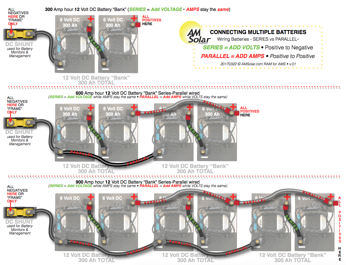
![[DIAGRAM] 4 6 Volt Battery Wiring Diagrams](https://i0.wp.com/www.etrailer.com/static/images/pics/q/u/qu124049_800.jpg?w=665&ssl=1)
Related Posts


