A backup camera wiring schematic is a diagram that outlines the electrical connections between a backup camera and the vehicle’s display system. It provides a clear visual guide for professionals installing the camera, ensuring proper functionality and avoiding potential electrical issues. An example of a backup camera wiring schematic is the one for a 2017 Honda Civic, which details the connections between the camera, the display unit, and the vehicle’s electrical system.
Backup camera wiring schematics are crucial for ensuring the correct installation of backup cameras. By following the schematic, installers can avoid miswiring, which can lead to malfunctions or safety hazards. The schematics also provide valuable information for troubleshooting any issues that may arise during or after installation. Additionally, backup camera wiring schematics have evolved over time, with modern systems utilizing digital communication protocols and wireless connectivity. These advancements have simplified installation and improved the overall functionality of backup cameras.
This article will explore the components of a backup camera wiring schematic, discuss the importance of following the schematic during installation, and provide insights into the historical development of backup camera technology. We will also delve into the benefits of using backup cameras and the legal considerations surrounding their use.
Backup camera wiring schematics are crucial for the proper installation and operation of backup cameras. They provide a clear visual guide for installers, ensuring that the camera is connected correctly to the vehicle’s display system and electrical system. Understanding the key aspects of backup camera wiring schematics is essential for professionals and enthusiasts alike.
- Components: Camera, display unit, wiring harness, connectors
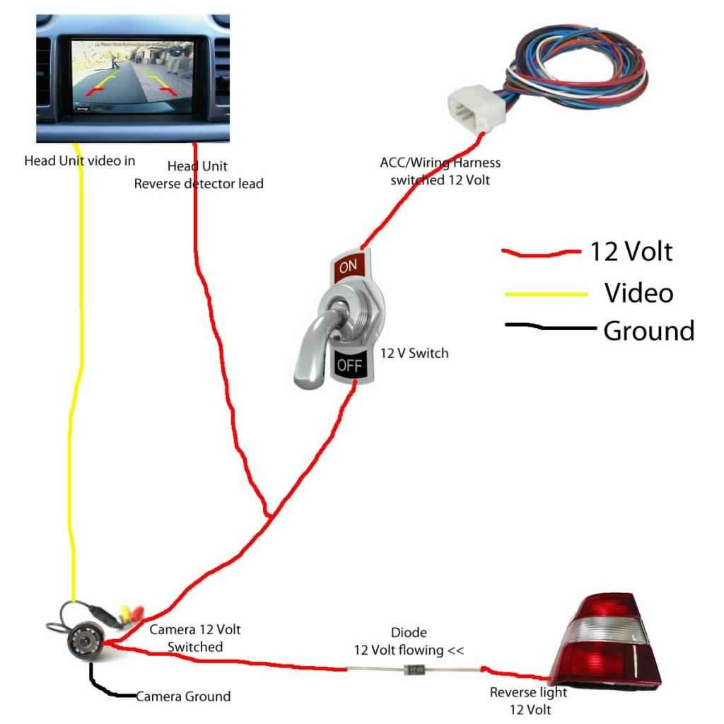
- Connections: Power, ground, video signal, trigger wire
- Installation: Following the schematic ensures proper connections
- Troubleshooting: Schematics aid in diagnosing and resolving issues
- Digital Communication: Modern systems use digital protocols for data transmission
- Wireless Connectivity: Some systems utilize wireless technology for video transmission
- Safety: Correct wiring is essential for camera functionality and safety
- Legal Considerations: Backup cameras may be required by law in some jurisdictions
- Vehicle Compatibility: Schematics are specific to each vehicle model
In conclusion, backup camera wiring schematics play a vital role in the effective installation and operation of backup cameras. By understanding the components, connections, and other key aspects of these schematics, installers can ensure that backup cameras function properly, enhancing safety and convenience for drivers. Additionally, an understanding of backup camera wiring schematics is essential for troubleshooting any issues that may arise during or after installation.
Components
In the context of backup camera wiring schematics, the components play a crucial role in establishing the connections necessary for the system to function effectively. The camera captures the rear-facing video, the display unit provides a visual representation of the camera’s feed, the wiring harness facilitates the transmission of power and signals between components, and the connectors ensure secure and reliable electrical connections. These components are interconnected and interdependent, forming the backbone of a functional backup camera system.
The backup camera wiring schematic serves as a blueprint for assembling these components and establishing the proper connections. It outlines the specific wiring configurations, pin assignments, and other technical details required for the system to operate seamlessly. Without a clear understanding of the components and their relationships as defined in the schematic, installers may encounter difficulties or introduce errors during installation, potentially compromising the functionality and safety of the backup camera system.
For instance, incorrect wiring of the camera’s power supply can lead to insufficient power reaching the camera, resulting in poor image quality or intermittent operation. Similarly, improper connections between the display unit and the wiring harness can cause video signal interference or complete loss of display. By adhering to the backup camera wiring schematic and ensuring the correct installation of each component, installers can avoid these potential issues and guarantee optimal performance of the backup camera system.
In conclusion, the components of a backup camera system, including the camera, display unit, wiring harness, and connectors, are critical elements that must be interconnected and configured according to the backup camera wiring schematic. Understanding the relationships between these components and the schematic is essential for successful installation, troubleshooting, and maintenance of the backup camera system.
Connections
In the context of backup camera wiring schematics, the connections between power, ground, video signal, and trigger wire are crucial for establishing a functional and reliable backup camera system. These connections provide the necessary electrical pathways for the camera to receive power, transmit video signals, and integrate with the vehicle’s electrical system.
The power connection supplies electrical power to the camera, enabling it to capture and process video footage. The ground connection provides a reference point for the electrical circuit, ensuring that the camera operates at the correct voltage level. The video signal connection transmits the video data captured by the camera to the display unit, allowing the driver to view the rear-facing surroundings. Finally, the trigger wire connection activates the backup camera when the vehicle is shifted into reverse, ensuring that the camera is only active when necessary.
Without these essential connections, the backup camera would be unable to function properly. Incorrect wiring or loose connections can lead to a variety of issues, such as poor image quality, intermittent operation, or complete system failure. Therefore, it is critical that installers follow the backup camera wiring schematic carefully and ensure that all connections are made securely.
For instance, in the backup camera wiring schematic for a 2017 Honda Accord, the power connection is made to the vehicle’s reverse light circuit, ensuring that the camera only receives power when the vehicle is in reverse gear. The ground connection is made to a metal chassis point, providing a stable reference for the electrical circuit. The video signal connection is made using a composite video cable, which transmits the video data from the camera to the display unit. Finally, the trigger wire connection is made to the vehicle’s reverse gear switch, activating the camera when the vehicle is shifted into reverse.
Understanding the connections between power, ground, video signal, and trigger wire is essential for successful installation, troubleshooting, and maintenance of backup camera systems. By adhering to the backup camera wiring schematic and ensuring that all connections are made correctly, installers can guarantee optimal performance and reliability of the backup camera system, enhancing safety and convenience for drivers.
Installation
Within the context of backup camera wiring schematics, the proper installation of connections is paramount for ensuring the functionality and reliability of the backup camera system. Following the schematic during installation serves as a crucial guide, providing detailed instructions on how to establish the necessary electrical connections between the camera, display unit, and vehicle’s electrical system. By adhering to the schematic, installers can avoid potential errors and ensure that the backup camera system operates as intended.
- Accurate Wiring: The schematic specifies the correct wire gauges and types to be used for each connection, ensuring that the electrical current is delivered safely and efficiently. Proper wiring prevents voltage drops, signal interference, and potential damage to the camera or other components.
- Secure Connections: The schematic provides guidance on how to securely connect wires using crimping tools, solder, or other methods. Loose or improperly connected wires can lead to intermittent operation, poor image quality, or complete system failure.
- Grounding: The schematic indicates the appropriate grounding points for the camera and display unit. Proper grounding provides a stable electrical reference and minimizes the risk of electrical noise or interference.
- Trigger Wire Activation: The schematic specifies how to connect the trigger wire to the vehicle’s reverse gear switch or other activation source. This ensures that the backup camera is only activated when the vehicle is in reverse, preventing unnecessary power consumption and potential distractions for the driver.
In conclusion, following the backup camera wiring schematic during installation is essential for establishing proper connections and ensuring the optimal performance of the backup camera system. By understanding the specific requirements outlined in the schematic, installers can avoid common pitfalls and ensure that the camera is integrated seamlessly into the vehicle’s electrical system. This not only enhances the safety and convenience of the backup camera system but also contributes to the overall reliability and longevity of the vehicle’s electrical components.
Troubleshooting
Troubleshooting backup camera issues requires a systematic approach, and the backup camera wiring schematic plays a critical role in guiding technicians through this process. By understanding the connections and components outlined in the schematic, technicians can identify potential failure points and isolate the root cause of the problem. For instance, if the backup camera display shows a blank screen, the schematic can help determine whether the issue lies with the camera itself, the wiring harness, or the display unit. The schematic provides a roadmap for tracing the electrical connections and identifying any breaks, shorts, or loose connections that may be causing the malfunction.
Real-life examples further illustrate the practical significance of backup camera wiring schematics in troubleshooting. In a case where the backup camera image is distorted or exhibits color issues, the schematic can guide the technician to check the video signal connection between the camera and the display unit. By identifying the specific wires responsible for transmitting the video signal, the technician can isolate the problem and determine whether the issue is caused by a faulty cable, a poor connection, or a problem with the camera or display unit itself. Similarly, if the backup camera fails to activate when the vehicle is shifted into reverse, the schematic can help troubleshoot the trigger wire connection, ensuring that the camera is receiving the necessary signal to turn on.
The understanding gained from backup camera wiring schematics empowers technicians to resolve issues efficiently and effectively. By pinpointing the exact location of the problem, they can avoid unnecessary guesswork and time-consuming trial-and-error methods. The schematic also serves as a valuable reference for future maintenance and repairs, ensuring that the backup camera system continues to function properly and provide drivers with enhanced visibility and safety.
Digital Communication
In the realm of backup camera wiring schematics, digital communication has revolutionized the way data is transmitted between the camera and the display unit. Modern backup camera systems leverage digital protocols to enhance image quality, reduce noise, and enable advanced features that improve the driver’s visibility and safety.
- Uncompressed Video Transmission: Digital communication allows for the transmission of uncompressed video data, resulting in higher-resolution images with minimal loss of detail.
- Noise Reduction: Digital protocols incorporate error-correction algorithms that effectively remove noise and interference from the video signal, ensuring a clear and stable image.
- Integration with Advanced Features: Digital communication enables the integration of advanced features such as lane departure warnings, blind-spot monitoring, and object detection, enhancing the driver’s awareness of their surroundings.
The adoption of digital communication in backup camera wiring schematics has significantly improved the overall performance and functionality of backup camera systems. Digital protocols provide a robust and zuverlssig data transmission method, ensuring that drivers have a clear and accurate view of the area behind their vehicle, contributing to increased safety and peace of mind.
Wireless Connectivity
In the realm of backup camera wiring schematics, wireless connectivity has emerged as a game-changing technology, revolutionizing the way video data is transmitted from the camera to the display unit. By eliminating the need for physical wiring between the two components, wireless connectivity offers a host of advantages, making backup camera systems more versatile, convenient, and aesthetically pleasing.
The impact of wireless connectivity on backup camera wiring schematics is significant. Traditional wiring schematics, which detail the physical connections between components, must be adapted to accommodate the wireless transmission of video data. This involves incorporating wireless transmitters and receivers into the schematic, ensuring compatibility between the camera and display unit, and specifying the wireless communication protocols used.
A real-life example of wireless connectivity in backup camera wiring schematics is the integration of Wi-Fi technology. Wi-Fi-based backup camera systems transmit video data wirelessly from the camera to a smartphone or tablet, which serves as the display unit. This eliminates the need for a dedicated display screen in the vehicle, providing greater flexibility and convenience for the driver.
The practical applications of wireless connectivity in backup camera wiring schematics extend beyond convenience. In commercial vehicles, such as buses and trucks, wireless connectivity allows for the installation of multiple backup cameras around the vehicle, providing the driver with a comprehensive view of their surroundings. This enhanced visibility is critical for safe maneuvering in tight spaces and reducing blind spots.
In summary, wireless connectivity has transformed backup camera wiring schematics, offering a number of benefits including increased flexibility, ease of installation, and enhanced safety. As wireless technology continues to advance, we can expect to see even greater integration of wireless connectivity in backup camera systems, further improving the driving experience and contributing to increased road safety.
Safety
In the context of backup camera wiring schematics, safety plays a paramount role. Correct wiring is not merely a matter of ensuring functionality; it is essential for maintaining the integrity of the camera system and safeguarding the well-being of drivers and passengers.
- Power Stability: Proper wiring ensures a stable power supply to the backup camera, preventing flickering or sudden loss of video feed. This uninterrupted power supply is crucial for reliable operation, especially in low-visibility conditions where the backup camera is most needed.
- Electrical Isolation: Correct wiring isolates the backup camera system from other electrical components in the vehicle, minimizing the risk of electrical interference or damage to the camera or other systems. This isolation helps maintain the integrity of the camera’s video signal and prevents potential hazards.
- Grounding: Proper grounding of the backup camera system provides a safe path for electrical current to flow, reducing the risk of electrical shocks or damage to the camera equipment. Adequate grounding also helps minimize electrical noise and ensures clear video transmission.
- Environmental Protection: Correct wiring includes the use of weather-resistant connectors and cables, protecting the backup camera system from moisture, dust, and other environmental factors. This protection is essential for maintaining reliable camera operation in all weather conditions, ensuring visibility and safety.
In conclusion, the safety implications of correct wiring in backup camera wiring schematics cannot be overstated. Proper wiring not only ensures the smooth operation of the camera system but also safeguards against potential hazards. By adhering to the guidelines outlined in the schematic, technicians can ensure that backup camera systems function reliably, providing drivers with the enhanced visibility and peace of mind they need to navigate safely.
Legal Considerations
In the context of “Backup Camera Wiring Schematic,” legal considerations play a significant role, as backup cameras may be mandated by law in certain jurisdictions. This legal requirement has implications for the design, installation, and use of backup camera systems, shaping the guidelines outlined in the wiring schematic.
- Legal Mandates: In some countries and states, regulations require the installation of backup cameras in new vehicles. These mandates specify the minimum field of view, image quality, and activation criteria for backup cameras, ensuring a consistent level of safety across the industry.
- Liability Implications: Backup camera systems can provide valuable evidence in the event of an accident. Proper installation and maintenance, as outlined in the wiring schematic, can help demonstrate due diligence and mitigate potential liability for manufacturers, installers, and drivers.
- Insurance Considerations: Insurance companies may offer discounts or reduced premiums to vehicles equipped with backup cameras, recognizing their role in reducing accidents and improving overall safety.
- International Standards: International organizations, such as the United Nations Economic Commission for Europe (UNECE), have established guidelines and regulations for backup camera systems. These standards aim to harmonize requirements across borders and ensure the safety and effectiveness of backup cameras globally.
In summary, legal considerations are intertwined with the design and implementation of backup camera wiring schematics. By understanding the legal mandates, liability implications, insurance considerations, and international standards, manufacturers, installers, and drivers can ensure that backup camera systems comply with the law and contribute to enhanced safety on the roads.
Vehicle Compatibility
In the context of “Backup Camera Wiring Schematic,” vehicle compatibility plays a crucial role. Backup camera wiring schematics are designed specifically for each vehicle model, taking into account the unique electrical architecture, mounting points, and display options. This specificity ensures that the backup camera system is properly integrated into the vehicle, providing optimal performance and safety.
The cause-and-effect relationship between vehicle compatibility and backup camera wiring schematics is straightforward. Without vehicle-specific wiring schematics, installers would face significant challenges in connecting the backup camera to the vehicle’s electrical system. The schematics provide detailed instructions on which wires to connect to which components, ensuring that the camera receives power, ground, and video signal correctly. Additionally, the schematics specify the mounting points for the camera and display unit, ensuring proper placement and alignment for optimal visibility.
Real-life examples further illustrate the importance of vehicle compatibility in backup camera wiring schematics. For instance, the backup camera wiring schematic for a 2018 Honda Civic will differ from that of a 2020 Toyota Camry. This is because the two vehicles have different electrical systems, mounting points, and display options. Using the incorrect wiring schematic can lead to improper installation, poor camera performance, or even electrical damage.
The practical applications of understanding vehicle compatibility in backup camera wiring schematics extend beyond ensuring proper installation. By using vehicle-specific schematics, installers can optimize the performance of the backup camera system. The schematics provide guidance on selecting the correct wire gauges, crimping connections securely, and routing wires safely to avoid interference. This attention to detail contributes to a reliable and long-lasting backup camera system.
In summary, vehicle compatibility is a critical component of backup camera wiring schematics. By using vehicle-specific schematics, installers can ensure proper integration of the backup camera system, maximizing its performance and safety benefits. This understanding is essential for professionals involved in the installation and maintenance of backup camera systems, ensuring that drivers have a clear and reliable view of their surroundings, contributing to safer driving.


Related Posts


