A Backup Camera Wiring Diagram is a visual representation of the electrical connections required to install a backup camera system in a vehicle. These diagrams typically depict the location of the camera, the path of the wiring harness, and the connections to the vehicle’s electrical system. An example of a real-world wiring diagram would be a visual guide for installing a backup camera in a specific make and model of car, such as a 2018 Toyota Camry.
Backup Camera Wiring Diagrams are important because they ensure the proper installation and operation of the camera system. By following the diagram, installers can connect the camera and its components correctly, ensuring a clear and reliable image on the vehicle’s display. Additionally, these diagrams improve safety by enabling the driver to connect the camera to the vehicle’s power source and ensure that the system is receiving the correct voltage.
Historically, backup camera systems were not prevalent in vehicles. However, advancements in technology and increased safety concerns have led to the widespread adoption of these systems. Backup Camera Wiring Diagrams have evolved to keep pace with these technological advancements, ensuring the proper installation and functionality of these crucial safety features.
In this article, we will delve deeper into the specifics of Backup Camera Wiring Diagrams, including their components, different types, and best practices for their use. By understanding these diagrams, you can effectively install or troubleshoot a backup camera system, enhancing the safety of your vehicle.
Backup Camera Wiring Diagrams are essential for ensuring the proper installation and operation of backup camera systems in vehicles. Understanding the various aspects of Backup Camera Wiring Diagrams is crucial for installers, technicians, and anyone interested in maintaining the safety and functionality of their vehicle’s camera system.
- Connection Points: Identify the specific locations where the backup camera, power source, and display are connected.
- Wire Types: Determine the types of wires used, such as coaxial cables, twisted pair, or wireless connections.
- Power Requirements: Specify the voltage and amperage required by the backup camera and its components.
- Camera Compatibility: Ensure that the wiring diagram is compatible with the specific model and make of the backup camera being installed.
- Display Integration: Describe how the backup camera will connect to the vehicle’s display, whether through a dedicated screen or the existing infotainment system.
- Troubleshooting Guide: Provide instructions for diagnosing and resolving common issues related to backup camera wiring.
- Safety Precautions: Highlight the importance of following proper safety precautions when working with electrical systems and handling backup camera components.
- Vehicle-Specific Considerations: Address any unique wiring requirements or challenges specific to different makes and models of vehicles.
- Advanced Features: Discuss the wiring diagrams for advanced features such as night vision, motion detection, and lane departure warnings.
- Legal Compliance: Ensure that the backup camera wiring meets all applicable legal standards and regulations.
These aspects provide a comprehensive understanding of Backup Camera Wiring Diagrams, enabling individuals to confidently install, troubleshoot, and maintain their vehicle’s backup camera systems. By referring to the wiring diagram and considering these aspects, users can ensure the proper functionality and reliability of their backup cameras, enhancing their driving safety and convenience.
Connection Points
Connection points are a critical component of any backup camera wiring diagram. They specify where the camera, power source, and display are connected, ensuring that the system functions correctly and provides a clear image. Without a clear understanding of the connection points, it would be difficult to establish a reliable connection between the components, potentially leading to system failure or poor image quality.
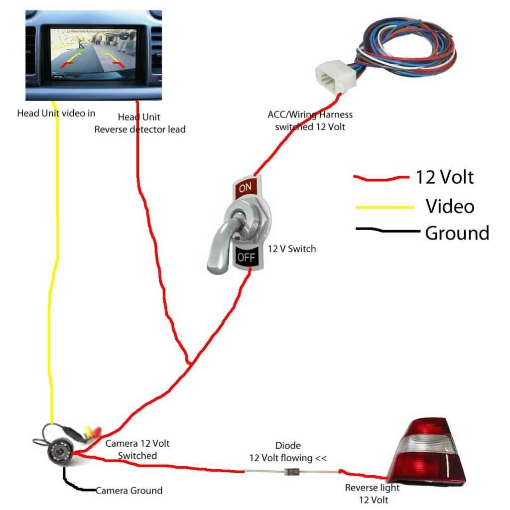
Real-life examples of connection points in a backup camera wiring diagram include the following:
The camera’s video output is typically connected to the display’s video input. The camera’s power wire is connected to the vehicle’s power source, such as the reverse light or a dedicated power outlet. The display’s power wire is connected to the vehicle’s power source, such as the ignition or a dedicated power outlet.
Understanding the connection points is essential for troubleshooting any issues with a backup camera system. If the image is unclear or the system is not functioning properly, checking the connection points is a crucial first step. Loose or damaged connections can be identified and fixed, ensuring that the system is operating at its optimal level.
Wire Types
Understanding the types of wires used in a backup camera wiring diagram is essential for ensuring a reliable and high-quality camera system. Different types of wires have unique characteristics that impact the transmission of video and power signals.
-
Coaxial Cable:
Coaxial cables are commonly used in backup camera systems due to their ability to transmit high-quality video signals over long distances with minimal interference. They consist of a central conductor surrounded by insulation and a braided shield, providing excellent protection against electromagnetic noise. -
Twisted Pair:
Twisted pair cables are another option for backup camera wiring. They consist of two insulated wires twisted together, which helps reduce electromagnetic interference and crosstalk. Twisted pair cables are typically more flexible and easier to install than coaxial cables but may have limitations on the distance and quality of video transmission. -
Wireless Connection:
Wireless backup camera systems transmit video signals using radio waves, eliminating the need for physical wires. They offer convenience and flexibility but may be susceptible to interference and signal dropouts, especially in areas with strong electromagnetic fields. -
Power Wires:
In addition to video cables, backup camera systems also require power wires to supply electricity to the camera and display. These wires typically have a larger gauge to handle the higher current requirements.
Selecting the appropriate wire types for a backup camera wiring diagram is crucial. Factors such as the length of the cable run, the desired video quality, and the presence of electromagnetic interference should be considered. By understanding the different wire types available, installers can design and implement a wiring diagram that meets the specific needs and requirements of the backup camera system.
Power Requirements
In the context of Backup Camera Wiring Diagrams, understanding the power requirements is essential for ensuring the proper functioning and longevity of the system. The diagram specifies the voltage and amperage required by the backup camera and its components, such as the display, to operate reliably and deliver a clear image.
-
Voltage Requirements
The wiring diagram indicates the specific voltage required by the backup camera and display. Common voltage requirements range from 12 volts to 24 volts, depending on the vehicle’s electrical system. -
Amperage Requirements
The amperage requirement specifies the amount of current the backup camera and display draw from the vehicle’s electrical system. Understanding the amperage requirements helps ensure that the power source can provide sufficient current without overloading or causing damage. -
Power Source
The wiring diagram identifies the power source for the backup camera system, whether it is connected to the vehicle’s reverse lights, a dedicated power outlet, or another suitable power source. -
Fusing
The diagram may also specify the use of fuses or circuit breakers to protect the backup camera system from electrical overloads or short circuits.
By adhering to the power requirements specified in the Backup Camera Wiring Diagram, installers can ensure that the system receives the correct voltage and amperage, resulting in optimal performance and longevity. Neglecting oring the power requirements can lead to insufficient power, poor image quality, or even damage to the backup camera or other components.
Camera Compatibility
In the realm of Backup Camera Wiring Diagrams, camera compatibility plays a pivotal role in ensuring a successful installation and optimal functioning of the backup camera system. The wiring diagram must be meticulously matched to the specific model and make of the backup camera being installed to establish seamless communication and operation.
Consider a scenario where a wiring diagram intended for a particular backup camera model is inadvertently used with a different camera model. This mismatch can lead to incorrect wiring connections, resulting in a range of issues. The backup camera may fail to power on, display a distorted or blank image, or exhibit erratic behavior. In severe cases, mismatched wiring can even damage the backup camera or other components of the system.
To prevent such problems, it is imperative to verify that the Backup Camera Wiring Diagram is compatible with the specific camera being installed. This involves consulting the manufacturer’s documentation or seeking guidance from qualified professionals. By adhering to the correct wiring diagram, installers can ensure that the camera receives the appropriate power and signal inputs, allowing it to function as intended.
In summary, camera compatibility is a critical aspect of Backup Camera Wiring Diagrams. Using a compatible wiring diagram ensures proper communication and operation between the backup camera and the vehicle’s electrical system. Neglecting camera compatibility can lead to suboptimal performance, system malfunctions, or even damage to components. Therefore, it is essential to carefully select and follow the correct wiring diagram for the specific backup camera model being installed.
Display Integration
Display integration is a crucial aspect of Backup Camera Wiring Diagrams, determining how the camera’s video feed will be displayed to the driver. This involves understanding the available options for connecting the backup camera to the vehicle’s display, ensuring compatibility, and considering factors such as screen size, resolution, and user interface.
-
Dedicated Screen
Some backup camera systems utilize a dedicated screen, typically mounted on the dashboard or rearview mirror. These screens are designed specifically for displaying the backup camera feed, providing a clear and dedicated view. -
Infotainment System Integration
Modern vehicles often integrate backup cameras with the existing infotainment system. The camera feed is displayed on the vehicle’s touchscreen display, allowing for seamless integration and control of the camera. -
Compatibility Considerations
Compatibility between the backup camera and the display is essential. The wiring diagram must account for the specific video format and resolution supported by the display. -
Resolution and Display Quality
The resolution and display quality of the backup camera system impact the clarity and visibility of the image. Higher resolution cameras and displays provide a sharper and more detailed image, enhancing safety.
Understanding display integration in Backup Camera Wiring Diagrams is crucial for selecting the appropriate components and ensuring a functional and reliable backup camera system. By considering the available options, compatibility, and display quality, installers can design and implement a system that meets the specific needs and preferences of the vehicle and driver.
Troubleshooting Guide
Within the context of Backup Camera Wiring Diagrams, troubleshooting instructions play a pivotal role in maintaining a functional and reliable backup camera system. These instructions provide step-by-step guidance for diagnosing and resolving common issues that may arise during installation, operation, or maintenance of the system.
The troubleshooting guide serves as a critical component of the Backup Camera Wiring Diagram, empowering users to identify and rectify issues without the need for extensive technical expertise. It complements the wiring diagram by offering practical solutions to potential challenges, ensuring that the system operates as intended.
Real-life examples of troubleshooting instructions within Backup Camera Wiring Diagrams include:
- Diagnosing and resolving issues related to poor image quality, such as blurry or distorted images.
- Troubleshooting electrical problems, such as power failures or intermittent connections.
- Identifying and fixing issues with the camera’s video feed, such as signal loss or interference.
Understanding the connection between the Troubleshooting Guide and the Backup Camera Wiring Diagram enables users to effectively maintain and troubleshoot their backup camera systems. This practical knowledge enhances safety and convenience, ensuring that the system operates reliably, providing drivers with a clear view of their surroundings.
Safety Precautions
Adhering to proper safety precautions is paramount when working with electrical systems and handling backup camera components. Neglecting these precautions can lead to electrical hazards, component damage, and even personal injury. Backup Camera Wiring Diagrams play a crucial role in ensuring safety by providing guidance on the proper handling and installation of these systems.
-
Electrical Hazards
Electrical systems in vehicles pose potential hazards, such as electrical shocks or fires. Understanding the electrical system, using insulated tools, and wearing appropriate protective gear are essential safety measures. -
Component Damage
Mishandling backup camera components, such as the camera itself, wiring, or connectors, can cause damage. Careful handling, following the wiring diagram, and using proper tools are crucial to prevent damage. -
Personal Injury
Improper handling of electrical components or sharp tools can lead to cuts, burns, or other injuries. Wearing protective gear, working in a well-lit area, and following the safety guidelines in the wiring diagram are essential. -
Legal Implications
Ignoring safety precautions may violate electrical codes or regulations, leading to legal consequences. Following the guidelines outlined in the wiring diagram ensures compliance with safety standards.
By emphasizing safety precautions in Backup Camera Wiring Diagrams, users are equipped with the necessary knowledge to handle and install backup camera systems safely and effectively. Neglecting these precautions can compromise the safety and functionality of the system, potentially leading to hazardous situations. Therefore, it is imperative to prioritize safety by adhering to the guidelines provided in the wiring diagram, ensuring a reliable and optimal backup camera system.
Vehicle-Specific Considerations
Vehicle-specific considerations are a critical component of Backup Camera Wiring Diagrams as they address the unique wiring requirements and challenges associated with different makes and models of vehicles. Every vehicle has its own electrical system, layout, and specific features that impact the installation and operation of a backup camera system. Failing to account for these vehicle-specific considerations can lead to improper installation, system malfunctions, or even damage to the vehicle’s electrical system.
Backup Camera Wiring Diagrams that incorporate vehicle-specific considerations provide detailed instructions and guidance tailored to the specific make and model of the vehicle being equipped. These diagrams identify any unique wiring requirements, such as the need for additional wiring harnesses, adapters, or modules, to ensure compatibility with the vehicle’s electrical system. They also address challenges that may arise due to the vehicle’s specific design or layout, such as limited space for mounting the camera or running wiring through tight compartments.
Understanding the connection between vehicle-specific considerations and Backup Camera Wiring Diagrams is essential for successful installation and operation of backup camera systems. By incorporating vehicle-specific considerations, wiring diagrams enable installers to anticipate and overcome challenges, ensuring a seamless integration of the backup camera system into the vehicle’s electrical system. This not only enhances the functionality and safety benefits of the backup camera but also protects the vehicle’s electrical system from potential damage.
Advanced Features
As backup camera technology advances, additional features are being integrated to enhance safety and convenience. These advanced features rely on specialized wiring diagrams to ensure proper installation and functionality. Understanding these diagrams is crucial for technicians and installers working with backup camera systems.
-
Night Vision
Night vision cameras utilize infrared technology to provide a clear image in low-light conditions. The wiring diagram specifies the connection to the vehicle’s power source and the integration with the display unit.
-
Motion Detection
Motion detection sensors trigger the backup camera to activate when movement is detected behind the vehicle. The wiring diagram outlines the connection to the camera and the integration with the vehicle’s electrical system.
-
Lane Departure Warnings
Lane departure warning systems use cameras to monitor the vehicle’s position within its lane. The wiring diagram provides instructions for connecting the cameras, sensors, and the display unit.
Advanced features in backup camera systems enhance safety by providing drivers with increased visibility and situational awareness. The corresponding wiring diagrams ensure the proper functioning of these features by guiding installers through the electrical connections. Understanding and utilizing these diagrams is essential for the effective installation and maintenance of backup camera systems.
Legal Compliance
Within the context of Backup Camera Wiring Diagrams, legal compliance plays a vital role in ensuring the safe and compliant installation and operation of backup camera systems. Adhering to legal standards and regulations is paramount to avoid potential legal liabilities, ensure the safety of drivers and passengers, and maintain the integrity of the vehicle’s electrical system.
-
Compliance with Vehicle Standards
Backup camera wiring must meet the safety and performance standards established by regulatory bodies for the specific make and model of the vehicle being equipped. These standards may vary depending on the jurisdiction and the year of manufacture, and they address aspects such as camera placement, field of view, and image quality.
-
Compatibility with Lighting Systems
The wiring of the backup camera system must be compatible with the vehicle’s existing lighting systems. This includes ensuring that the backup camera activates automatically when the vehicle is shifted into reverse and that the camera’s illumination does not interfere with the visibility of other lights, such as taillights or brake lights.
-
Electrical Safety
The wiring of the backup camera system must adhere to established electrical safety codes and standards. This includes using proper gauge wires, protecting connections from moisture and corrosion, and ensuring that the system does not overload the vehicle’s electrical system.
-
Documentation and Labeling
Proper documentation and labeling of the backup camera wiring is crucial for future maintenance, troubleshooting, and inspections. This includes maintaining records of the installation, including the wiring diagram, and labeling wires and connectors clearly for easy identification.
Understanding the legal compliance requirements related to Backup Camera Wiring Diagrams empowers technicians, installers, and vehicle owners to ensure that their backup camera systems are installed and operated in a safe, compliant, and reliable manner. Neglecting legal compliance can lead to compromised safety, legal penalties, and potential insurance issues.


Related Posts


