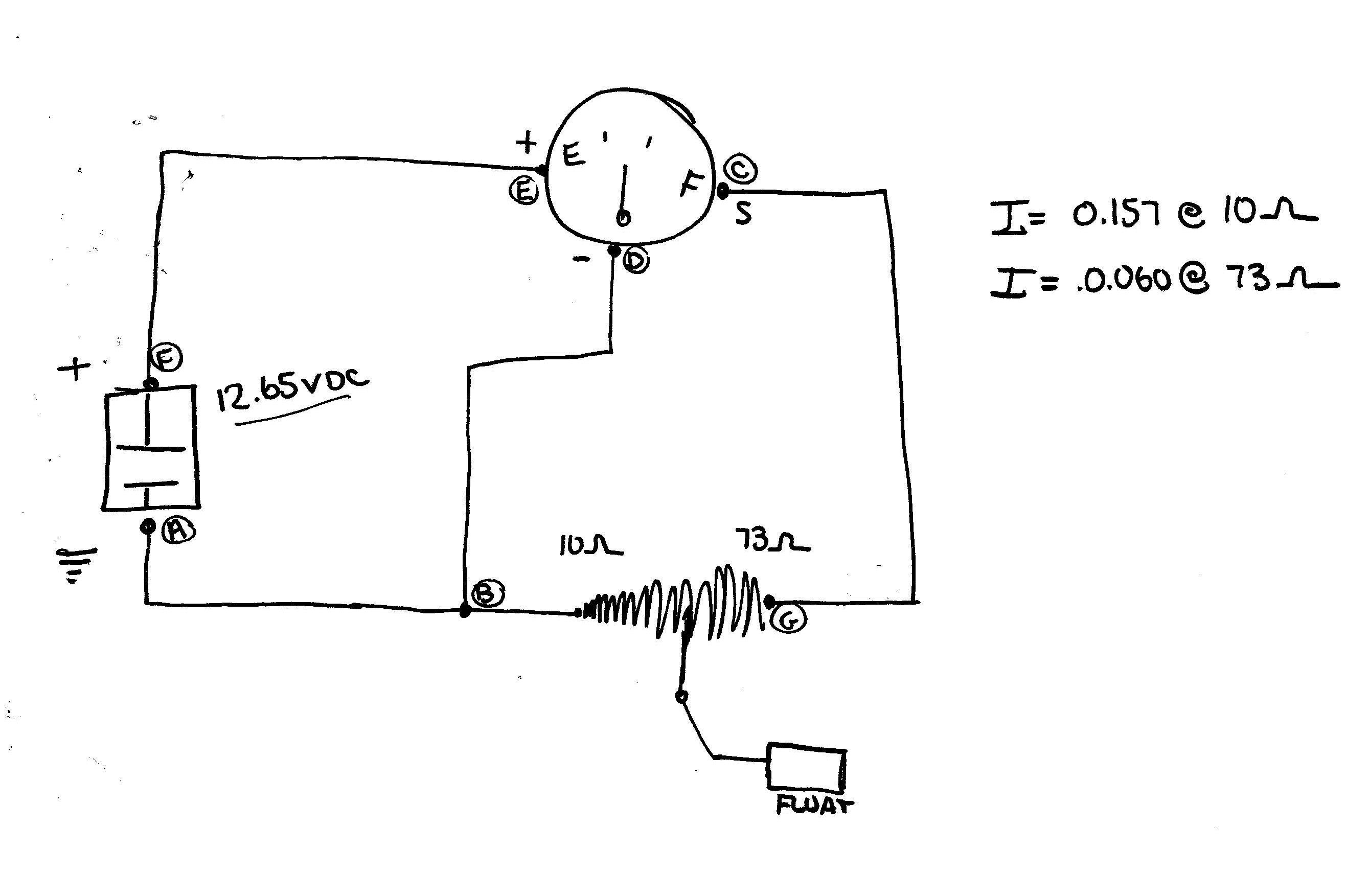
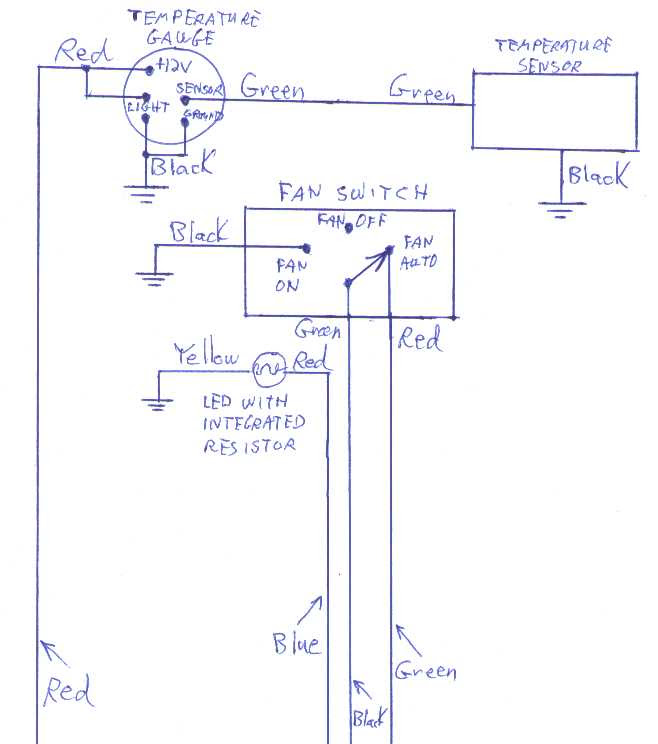
An Autometer Fuel Gauge Wiring Diagram outlines the electrical connections required to install a fuel gauge from the Autometer brand into a specific vehicle. It depicts the wiring paths, terminals, and sensors involved, serving as a blueprint for proper installation.
By following the diagram, one can ensure the accurate functioning of the fuel gauge and avoid potential electrical hazards. It is especially valuable for vehicles with non-standard fuel systems or aftermarket fuel modifications, where custom wiring may be necessary. The diagram also highlights the compatibility of the fuel gauge with various fuel sender unit configurations.
The development of standardized wiring diagrams for automotive instrumentation has greatly simplified the process of installing and maintaining vehicle gauges, enhancing safety and reliability. This article delves deeper into the intricacies of Autometer Fuel Gauge Wiring Diagrams, providing detailed explanations of each component and highlighting advanced features and troubleshooting techniques.
Autometer Fuel Gauge Wiring Diagrams hold significance in the precise installation and operation of fuel gauges, providing clear instructions on electrical connections and component interactions. To thoroughly understand these diagrams, it is essential to examine their key aspects:
- Compatibility: Compatibility with specific vehicle models and fuel system configurations.
- Wiring Paths: Precise delineation of wire routing and terminal connections.
- Sensor Integration: Depiction of connections to fuel sender units and other relevant sensors.
- Grounding: Proper grounding techniques to ensure accurate gauge readings.
- Illumination: Wiring instructions for gauge and dimming functionality.
- Power Source: Identification of the appropriate power source and its connection.
- Gauge Calibration: Calibration procedures to ensure accurate fuel level readings.
- Troubleshooting: Diagnostic steps to identify and resolve potential wiring issues.
- Safety Precautions: Safety guidelines for handling electrical components.
- Customization: Considerations for modifying the wiring diagram to accommodate specific vehicle needs.
These aspects collectively form the backbone of Autometer Fuel Gauge Wiring Diagrams, enabling their effective use in various automotive applications. Understanding these aspects empowers technicians and enthusiasts to install and maintain fuel gauges with precision, ensuring reliable fuel level monitoring and safe vehicle operation.
Compatibility
Within the context of Autometer Fuel Gauge Wiring Diagrams, compatibility plays a pivotal role. It ensures that the fuel gauge is properly matched to the specific vehicle model and its unique fuel system configuration. This compatibility encompasses various aspects:
- Vehicle Model Compatibility: Autometer Fuel Gauge Wiring Diagrams are designed to be compatible with specific vehicle models, taking into account the electrical system architecture, fuel tank shape, and fuel sender unit type.
- Fuel System Configuration: The wiring diagram must align with the vehicle’s fuel system configuration, whether it employs a single fuel tank or multiple tanks, and whether it has a mechanical or electrical fuel sender unit.
- Fuel Sender Unit Compatibility: The diagram provides instructions for interfacing the fuel gauge with the vehicle’s specific fuel sender unit, ensuring accurate fuel level readings and proper gauge operation.
- Customization Considerations: In some cases, modifications to the wiring diagram may be necessary to accommodate non-standard fuel system configurations or custom fuel tank installations.
Understanding and adhering to compatibility guidelines are essential for successful installation and operation of Autometer Fuel Gauge Wiring Diagrams. By matching the diagram to the specific vehicle model and fuel system configuration, technicians can ensure precise fuel level monitoring, reliable gauge readings, and safe vehicle operation.
Wiring Paths
Within the framework of Autometer Fuel Gauge Wiring Diagrams, the precise delineation of wire routing and terminal connections stands as a cornerstone for ensuring accurate fuel level readings and reliable gauge operation. It involves meticulously specifying the path of each wire, along with its corresponding terminal connections, to establish a functional electrical circuit.
- Wire Gauge and Material: The wiring diagram specifies the appropriate wire gauge and material for each connection, considering factors such as current carrying capacity, voltage drop, and resistance to ensure optimal signal transmission.
- Terminal Identification: Each terminal on the fuel gauge and sender unit is clearly labeled in the diagram, enabling technicians to make correct connections and avoid miswiring.
- Grounding Points: Proper grounding is crucial for accurate gauge readings. The diagram identifies the designated grounding points on the vehicle’s chassis, ensuring a stable electrical reference.
- Power Source Connection: The wiring diagram indicates the appropriate power source for the fuel gauge, whether it be a switched ignition source or a constant power source, to ensure reliable gauge operation.
By adhering to the precisely defined wiring paths and terminal connections outlined in the Autometer Fuel Gauge Wiring Diagram, technicians can establish a robust electrical circuit that delivers accurate fuel level readings. This not only enhances the functionality of the fuel gauge but also contributes to the overall safety and reliability of the vehicle’s fuel system.
Sensor Integration
Within the framework of Autometer Fuel Gauge Wiring Diagrams, the depiction of connections to fuel sender units and other relevant sensors plays a critical role in establishing an accurate and reliable fuel monitoring system. Fuel sender units, acting as the primary source of fuel level information, transmit signals to the fuel gauge, enabling the display of real-time fuel levels.
The wiring diagram meticulously outlines the electrical connections between the fuel gauge and the fuel sender unit, ensuring proper signal transmission and accurate fuel level readings. It specifies the type of fuel sender unit compatible with the fuel gauge, whether it employs a resistive or voltage-based sensing mechanism. Additionally, the diagram may include instructions for interfacing with other relevant sensors, such as low fuel level warning sensors or fuel pressure sensors, to provide comprehensive fuel system monitoring.
Understanding the sensor integration aspect of Autometer Fuel Gauge Wiring Diagrams empowers technicians to correctly connect the fuel gauge to the vehicle’s fuel system. By following the specified wiring paths and terminal connections, they can ensure that the fuel gauge receives accurate and reliable signals from the fuel sender unit and other sensors. This precise sensor integration contributes to the overall accuracy and functionality of the fuel monitoring system, aiding in efficient fuel management and safe vehicle operation.
Grounding
Within the context of Autometer Fuel Gauge Wiring Diagrams, proper grounding techniques play a critical role in ensuring accurate fuel gauge readings and reliable operation of the fuel monitoring system. Grounding establishes a reference point for electrical circuits, providing a stable electrical path for current to flow and preventing voltage fluctuations that could interfere with gauge readings.
- Grounding Points: The wiring diagram specifies designated grounding points on the vehicle’s chassis, which provide a low-resistance path to ground. These points are carefully selected to minimize electrical noise and ensure a stable reference for the fuel gauge circuit.
- Ground Wire Gauge: The diagram specifies the appropriate gauge for the ground wire, which is typically thicker than the signal wires to ensure adequate current carrying capacity and minimize voltage drop.
- Multiple Ground Connections: In some cases, the wiring diagram may recommend multiple grounding points to enhance the stability of the ground connection and reduce the likelihood of intermittent readings.
- Chassis Grounding: The fuel gauge and sender unit are often grounded to the vehicle’s chassis, which provides a solid and reliable ground reference. The diagram specifies the proper attachment points and hardware to ensure a secure and corrosion-resistant connection.
By adhering to the grounding techniques outlined in the Autometer Fuel Gauge Wiring Diagram, technicians can establish a robust electrical circuit that minimizes electrical noise, ensures accurate gauge readings, and promotes the reliable operation of the fuel monitoring system. Proper grounding practices contribute to the overall safety and functionality of the vehicle’s fuel system.
Illumination
Within the comprehensive framework of Autometer Fuel Gauge Wiring Diagrams, the aspect of “Illumination: Wiring instructions for gauge and dimming functionality” holds significant importance. It encompasses the electrical connections and components necessary for illuminating the fuel gauge and enabling adjustable brightness levels, contributing to enhanced visibility and user experience.
- Gauge : This section of the wiring diagram provides instructions for connecting the fuel gauge to a power source, ensuring that the gauge ( means illumination in Russian) is functional. It specifies the appropriate wire gauge, terminal connections, and polarity to achieve proper illumination.
- Dimming Functionality: The wiring diagram may include instructions for implementing dimming functionality, allowing the user to adjust the brightness of the gauge to suit their preference or ambient lighting conditions. This typically involves connecting the fuel gauge to a dimmer switch or a variable resistor.
- Compatibility with Dash Lighting: The wiring diagram considers the compatibility of the fuel gauge with the vehicle’s dashboard lighting system. It provides guidance on connecting the fuel gauge to the dashboard dimmer switch, enabling the gauge to dim in conjunction with the other dashboard lights.
- Additional Illumination Options: Some Autometer Fuel Gauge Wiring Diagrams may include instructions for connecting additional illumination sources, such as LED strips or rings, to further enhance the visibility and aesthetics of the fuel gauge.
By understanding and following the “Illumination: Wiring instructions for gauge and dimming functionality” aspect of the Autometer Fuel Gauge Wiring Diagram, technicians can ensure that the fuel gauge is properly illuminated and integrated with the vehicle’s lighting system. This contributes to improved visibility, user convenience, and a cohesive aesthetic within the vehicle’s interior.
Power Source
In the context of “Autometer Fuel Gauge Wiring Diagram”, the aspect of “Power Source: Identification of the appropriate power source and its connection” holds critical importance, as it ensures that the fuel gauge receives the necessary electrical power to function accurately and reliably. Determining the appropriate power source and establishing a proper connection involve several key considerations and components:
- Battery Connection: The fuel gauge typically draws power from the vehicle’s battery, which serves as the primary power source for electrical components. The wiring diagram specifies the correct connection point on the battery, ensuring a stable and reliable power supply.
- Ignition Switch: In some cases, the fuel gauge may be connected to the ignition switch, which provides power only when the ignition is turned on. This configuration ensures that the fuel gauge is active only when the vehicle is in operation.
- Voltage Regulator: To protect the fuel gauge from voltage fluctuations and surges, a voltage regulator may be incorporated into the wiring diagram. This component stabilizes the voltage supplied to the fuel gauge, ensuring accurate readings and preventing damage.
- Fuse Protection: The wiring diagram often includes a fuse in the power supply circuit to safeguard the fuel gauge from electrical overloads and short circuits. The fuse acts as a sacrificial component, breaking the circuit if excessive current flows, protecting the fuel gauge and other electrical components.
By carefully considering these components and following the guidelines outlined in the “Power Source: Identification of the appropriate power source and its connection” aspect of the Autometer Fuel Gauge Wiring Diagram, technicians can ensure that the fuel gauge is properly powered, protected from electrical hazards, and capable of providing accurate fuel level readings.
Gauge Calibration
Within the comprehensive framework of “Autometer Fuel Gauge Wiring Diagram”, the concept of “Gauge Calibration: Calibration procedures to ensure accurate fuel level readings” plays a pivotal role in guaranteeing the reliability and precision of fuel level measurements. This process involves adjusting the fuel gauge to align its readings with the actual fuel level in the vehicle’s tank, ensuring that drivers have access to accurate information regarding their fuel status.
- Float Adjustment: The float, a key component of the fuel sender unit, moves in response to fuel level changes. Proper float adjustment ensures that the float’s position corresponds accurately to the fuel level, enabling the fuel gauge to provide precise readings.
- Sender Unit Calibration: The fuel sender unit converts the float’s position into an electrical signal that is transmitted to the fuel gauge. Calibrating the sender unit involves fine-tuning its output signal to match the specific characteristics of the fuel tank and fuel gauge, ensuring accurate readings across the entire fuel level range.
- Gauge Scaling: The fuel gauge converts the electrical signal from the sender unit into a visual representation of the fuel level. Gauge scaling involves adjusting the gauge’s internal circuitry to match the specific fuel tank capacity and sender unit output, ensuring that the fuel level readings are properly scaled and displayed on the gauge.
- Linearity Correction: In some cases, the relationship between the fuel sender unit output and the actual fuel level may not be perfectly linear. Linearity correction involves adjusting the fuel gauge’s response to compensate for any non-linearities, ensuring that the gauge readings remain accurate throughout the entire fuel level range.
By incorporating “Gauge Calibration: Calibration procedures to ensure accurate fuel level readings” into the “Autometer Fuel Gauge Wiring Diagram”, technicians can ensure that the fuel gauge provides drivers with reliable and precise information about their vehicle’s fuel status. This not only enhances the overall driving experience but also contributes to efficient fuel management and safe vehicle operation.
Troubleshooting
When dealing with “Autometer Fuel Gauge Wiring Diagram”, the aspect of “Troubleshooting: Diagnostic steps to identify and resolve potential wiring issues” takes on paramount importance. Wiring issues can manifest in various forms, ranging from incorrect gauge readings to complete gauge failure. To effectively address these issues, a systematic approach to troubleshooting is crucial.
-
Electrical Continuity Testing:
Using a multimeter, technicians can check for electrical continuity throughout the wiring harness, ensuring that current is flowing properly from the power source to the fuel gauge and sender unit. Broken wires, loose connections, and faulty components can be identified and rectified. -
Ground Verification:
Proper grounding is essential for accurate gauge readings. Troubleshooting involves verifying the integrity of the ground connection between the fuel gauge, sender unit, and the vehicle’s chassis. Poor grounding can lead to erratic gauge behavior and incorrect readings. -
Signal Tracing:
In cases where the gauge is not receiving a signal from the sender unit, signal tracing techniques can be employed. By injecting a test signal into the wiring harness and monitoring its progress, technicians can pinpoint the location of any breaks or faults in the signal path. -
Component Replacement:
If all other troubleshooting steps fail to resolve the issue, replacing faulty components may be necessary. This could involve replacing the fuel gauge, sender unit, or any other components identified as defective during the troubleshooting process.
By incorporating a robust “Troubleshooting: Diagnostic steps to identify and resolve potential wiring issues” section within the “Autometer Fuel Gauge Wiring Diagram”, technicians are empowered with the knowledge and procedures to effectively diagnose and rectify wiring problems. This not only ensures accurate fuel level readings but also contributes to the overall reliability and safety of the vehicle’s fuel system.
Safety Precautions
In the realm of “Autometer Fuel Gauge Wiring Diagram”, the significance of “Safety Precautions: Safety guidelines for handling electrical components” cannot be overstated. These precautions form an indispensable component of the wiring diagram, providing crucial instructions to ensure the safety of individuals working with electrical systems.
Electrical components, if mishandled, can pose significant risks, including electrical shock, burns, and even fires. “Safety Precautions: Safety guidelines for handling electrical components” address these risks by outlining proper handling techniques, protective measures, and emergency procedures. By adhering to these guidelines, individuals can minimize the likelihood of accidents and ensure a safe working environment.
For instance, the wiring diagram emphasizes the importance of wearing appropriate personal protective equipment (PPE) when handling electrical components. This includes insulated gloves, safety glasses, and flame-resistant clothing. Additionally, it instructs technicians to use tools that are properly insulated and rated for the specific electrical work being performed.
Furthermore, “Safety Precautions: Safety guidelines for handling electrical components” provide guidance on proper grounding techniques, circuit isolation, and voltage testing procedures. These measures are essential to prevent electrical shocks and ensure the safe operation of fuel gauge wiring systems.
By incorporating “Safety Precautions: Safety guidelines for handling electrical components” into the “Autometer Fuel Gauge Wiring Diagram”, technicians are not only provided with instructions for installing and maintaining fuel gauges but also with critical safety information. This understanding empowers them to work confidently and effectively with electrical systems, minimizing risks and ensuring the safety of themselves and others.
Customization
Within the context of “Autometer Fuel Gauge Wiring Diagram”, “Customization: Considerations for modifying the wiring diagram to accommodate specific vehicle needs.” assumes a critical role in adapting the standard wiring diagram to unique vehicle requirements. The significance stems from the fact that not all vehicles conform to the exact specifications anticipated by the generic wiring diagram.
Real-life examples of “Customization: Considerations for modifying the wiring diagram to accommodate specific vehicle needs.” arise when dealing with aftermarket fuel system modifications or non-standard vehicle configurations. These scenarios demand adjustments to the wiring diagram to ensure compatibility and proper functionality of the fuel gauge.
For instance, installing an aftermarket fuel tank may require extending the wiring harness to reach the new tank’s location. Additionally, vehicles with custom fuel system configurations, such as dual fuel tanks or modified fuel lines, necessitate modifications to the wiring diagram to accommodate the altered fuel system architecture.
Understanding “Customization: Considerations for modifying the wiring diagram to accommodate specific vehicle needs.” empowers individuals to adapt the “Autometer Fuel Gauge Wiring Diagram” to their specific vehicle’s unique requirements. This understanding equips technicians and enthusiasts with the knowledge to tackle custom installations and modifications, ensuring accurate fuel level readings and reliable gauge operation.


Related Posts


