Audio Jack Wiring refers to the arrangement and assembly of wires within an audio jack. It involves connecting wires to specific terminals in a standardized manner to enable the transmission of audio signals between devices.
Audio jack wiring is crucial for establishing connections between audio sources and outputs, such as headphones, speakers, and other sound systems. It ensures proper signal transfer, preventing distortions, noise, or complete signal loss.
The development of standardized audio jacks, like the TRS (Tip, Ring, Sleeve) and TS (Tip, Sleeve) connectors, has played a significant role in streamlining audio wiring practices. These standardized jacks allow for consistency and compatibility among different audio devices.
Audio jack wiring plays a crucial role in connecting audio devices, ensuring seamless signal transmission. Understanding its key aspects is essential for effective wiring practices and optimal audio experiences.
- Standardization: Standardized audio jacks (e.g., TRS, TS) ensure compatibility and consistency among different audio devices.
- Signal Transmission: Wiring configurations determine which signals (e.g., left/right audio, microphone) are transmitted through the jack.
- Connector Types: Various connector types (e.g., male, female, RCA, XLR) are used for different applications and devices.
- Wire Gauge: The thickness of the wires used affects signal quality and power handling.
- Soldering Techniques: Proper soldering techniques ensure secure connections and prevent signal loss.
- Shielding: Shielded cables minimize electromagnetic interference, preserving signal integrity.
- Polarity: Maintaining correct wire polarity ensures proper signal flow and prevents phase issues.
- Testing: Testing continuity and signal flow before use is crucial to identify and resolve any wiring errors.
- Safety: Understanding wiring standards and precautions ensures safe handling and operation of audio equipment.
These aspects are interconnected and contribute to the overall functionality and quality of audio jack wiring. Proper attention to these aspects ensures reliable audio connections, enhances signal transmission, and prevents potential issues.
Standardization
In the realm of “Audio Jack Wiring,” “Standardization” plays a pivotal role in ensuring seamless connectivity and signal transmission between diverse audio devices. Standardized audio jacks, such as TRS (Tip, Ring, Sleeve) and TS (Tip, Sleeve), have been instrumental in establishing a common language for audio connections.
- Connector Types: TRS and TS jacks come in male and female configurations, allowing for secure connections between different devices. Male connectors (plugs) fit into female connectors (sockets), ensuring proper signal flow.
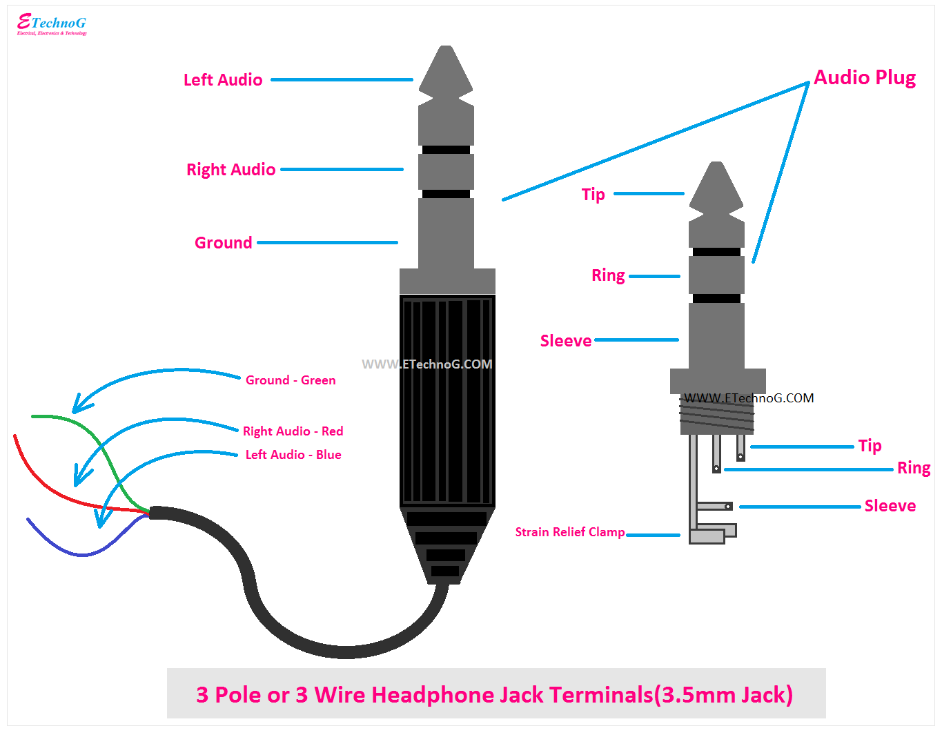
- Signal Configuration: TRS jacks accommodate three conductors, enabling the transmission of stereo audio signals (left, right, and ground), while TS jacks carry two conductors, suitable for mono audio signals.
- Compatibility: Standardized jacks ensure compatibility among devices from different manufacturers. A TRS plug from one device can connect to a TRS socket on another device, regardless of brand or model.
- Convenience: Standardization simplifies the process of connecting audio equipment. Users can easily identify and connect compatible jacks, eliminating the need for adapters or custom wiring.
In summary, standardization of audio jacks through TRS and TS connectors provides a universal framework for audio connections, ensuring compatibility, signal integrity, and ease of use. These standardized jacks have become the cornerstone of modern audio systems, enabling seamless integration and reliable signal transmission between various devices.
Signal Transmission
In the realm of “Audio Jack Wiring,” “Signal Transmission” takes center stage, as it is the very purpose of these intricate connections. Wiring configurations play a pivotal role in determining which signals are transmitted through the jack, shaping the flow of audio information between devices.
Imagine a symphony orchestra, where each instrument represents a different audio signal (e.g., left audio, right audio, microphone). The wiring configuration acts as the conductor’s baton, directing these signals to their designated paths. Each signal is assigned to a specific wire and terminal within the audio jack, ensuring proper transmission and separation.
- Stereo Audio: TRS jacks, with their three conductors, enable the transmission of stereo audio signals, carrying both left and right audio channels independently.
- Mono Audio: TS jacks, with their two conductors, are suitable for mono audio signals, where both channels are combined into a single signal.
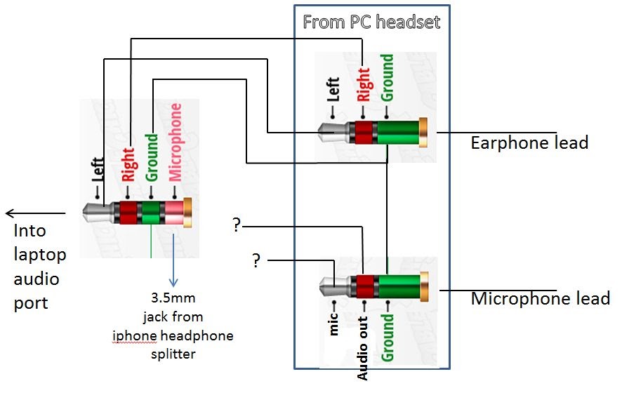
- Microphone Signals: Audio jacks can also accommodate microphone signals, which require a different wiring configuration to provide power and signal transmission.
Understanding the relationship between wiring configurations and signal transmission is crucial for effective audio jack wiring. Improper wiring can lead to signal loss, noise, or even damage to equipment. By carefully following wiring diagrams and industry standards, technicians can ensure that audio signals are transmitted accurately and reliably.
In conclusion, the wiring configurations within audio jacks serve as the backbone for signal transmission, determining which signals flow through the jack and shaping the overall audio experience. This understanding is essential for both the design and implementation of audio systems, ensuring that sound is transmitted with clarity, fidelity, and purpose.
Connector Types
In the realm of “Audio Jack Wiring,” “Connector Types” emerge as a crucial aspect, defining the physical interface through which audio signals are transmitted between devices. The choice of connector type depends on various factors, including the application, device compatibility, and signal requirements.
- Male and Female Connectors: Connectors come in male and female configurations, designed to fit together securely. Male connectors (plugs) have protruding pins that insert into the corresponding holes of female connectors (sockets).
- RCA Connectors: RCA connectors, also known as phono connectors, are commonly used for analog audio and video signals. They feature a circular shape with a central pin surrounded by a metal shield, ensuring reliable signal transmission.
- XLR Connectors: XLR connectors are professional-grade connectors primarily used for balanced audio signals in live sound, recording studios, and broadcasting. They offer excellent noise rejection and secure locking mechanisms.
- Other Connector Types: Beyond these common types, various other connector types exist, each tailored to specific applications, such as TRS (Tip, Ring, Sleeve) jacks for stereo audio, banana plugs for speaker connections, and DIN connectors for MIDI (Musical Instrument Digital Interface).
Understanding the different connector types and their applications is essential for effective audio jack wiring. Proper selection of connectors ensures compatibility between devices, minimizes signal loss, and optimizes audio performance. By carefully considering the requirements of each application, technicians and audio enthusiasts can choose the appropriate connector types, ensuring seamless signal transmission and a high-quality audio experience.
Wire Gauge
In the realm of “Audio Jack Wiring,” wire gauge plays a pivotal role in ensuring optimal signal transmission and power handling. The thickness of the wires, measured in American Wire Gauge (AWG), directly influences the electrical properties and performance of the audio jack.
- Signal Quality: Thicker wires (lower AWG number) offer lower resistance, resulting in reduced signal loss and improved sound quality. Thin wires (higher AWG number) can introduce significant resistance, leading to signal degradation and potential distortion.
- Power Handling: The thickness of the wires also affects the amount of power that can be transmitted through the audio jack. Thicker wires can handle higher currents, making them suitable for applications requiring significant power, such as powering speakers or subwoofers.
- Durability: Thicker wires are generally more durable and less prone to breakage, ensuring long-lasting performance and reliability in demanding environments.
- Flexibility: Thinner wires are more flexible and easier to work with, making them suitable for applications where space is constrained or frequent bending is required.
Understanding the relationship between wire gauge and signal quality, power handling, durability, and flexibility is crucial for effective audio jack wiring. By carefully selecting the appropriate wire gauge for the intended application, technicians and audio enthusiasts can optimize audio performance, ensure reliable signal transmission, and enhance the overall durability of their audio systems.
Soldering Techniques
In the realm of “Audio Jack Wiring,” “Soldering Techniques” emerge as a crucial aspect, influencing the overall reliability, performance, and longevity of audio connections. Proper soldering techniques are essential for establishing secure electrical connections between wires and audio jack terminals, preventing signal loss and ensuring optimal audio signal transmission.
- Solder Joint Quality: The quality of the solder joint is paramount in ensuring a secure connection. A well-soldered joint creates a strong mechanical bond between the wire and terminal, preventing loose connections and intermittent signal loss.
- Flux Usage: Flux plays a vital role in the soldering process by removing oxides and impurities from the surfaces to be joined. Proper flux application promotes a clean and strong solder joint, enhancing electrical conductivity and preventing corrosion.
- Solder Type: Choosing the appropriate solder type is essential. Lead-based solders provide excellent electrical conductivity, while lead-free solders offer environmental benefits. The solder type should be compatible with the materials being joined.
- Soldering Iron Temperature: The soldering iron temperature must be carefully controlled to achieve optimal results. Excessive heat can damage the components, while insufficient heat can result in poor solder joints. Using a temperature-controlled soldering iron ensures precise temperature regulation.
Mastering proper soldering techniques is crucial for effective “Audio Jack Wiring.” By meticulously following these techniques, audio enthusiasts and technicians can create reliable and long-lasting audio connections, ensuring pristine sound transmission and minimizing signal loss. These techniques form the foundation of high-quality audio installations, contributing to an immersive and enjoyable listening experience.
Shielding
In the realm of “Audio Jack Wiring,” shielding plays a critical role in preserving signal integrity and ensuring optimal audio transmission. Shielded cables employ a protective layer to safeguard the audio signals from external electromagnetic interference (EMI) and radio frequency interference (RFI), which can degrade signal quality and introduce noise.
- Conductive Shield: Shielded cables incorporate a conductive layer, typically braided or foil, around the inner conductors. This shield acts as a barrier, diverting EMI and RFI away from the signal path.
- Ground Connection: The shield is connected to the ground terminal of the audio jack, providing a low-impedance path for EMI and RFI to dissipate. Proper grounding ensures effective shielding.
- Cable Quality: The quality of the shield material and its coverage are crucial. High-quality shields provide better protection against EMI and RFI, resulting in improved signal-to-noise ratio.
- Connector Design: Shielded audio jacks feature metal shells that maintain the continuity of the shield, preventing EMI and RFI from entering the connection.
Shielding in audio jack wiring is essential for maintaining pristine audio signals, especially in environments with high levels of electromagnetic noise. By mitigating EMI and RFI, shielded cables ensure clear and accurate audio transmission, preserving the integrity of the audio signal and delivering an immersive listening experience.
Polarity
In “Audio Jack Wiring,” polarity plays a crucial role in ensuring proper signal flow and preventing phase issues. Polarity refers to the orientation of electrical connections, specifically the positive (+) and negative (-) terminals. Maintaining correct polarity is essential for achieving accurate and coherent audio transmission.
When audio signals are wired with incorrect polarity, it can result in phase cancellation, where the positive and negative waveforms of the signal interfere with each other, leading to reduced volume, distorted sound, or even complete signal loss. This can be particularly noticeable in stereo systems, where incorrect polarity can cause instruments or vocals to sound out of phase, resulting in a disorienting and unnatural listening experience.
To ensure proper polarity, it is important to adhere to the following guidelines when wiring audio jacks:
- Identify the positive (+) and negative (-) terminals on the audio jack and the corresponding wires.
- Connect the positive wire to the positive terminal and the negative wire to the negative terminal.
- Use color-coded wires or a multimeter to verify the polarity before making the connections.
Understanding and maintaining correct polarity is a critical component of “Audio Jack Wiring.” By paying attention to polarity, audio enthusiasts and professionals can ensure that audio signals are transmitted accurately and in phase, resulting in optimal sound quality and an immersive listening experience.
Testing
In the realm of “Audio Jack Wiring,” testing plays a pivotal role in ensuring the integrity and functionality of audio connections. Testing continuity and signal flow before use is a critical step that helps identify and resolve any wiring errors, preventing potential issues and ensuring optimal audio performance.
Continuity testing involves using a multimeter or continuity tester to check if there is a complete electrical path between two points in a circuit, such as between the terminals of an audio jack and the corresponding wires. By ensuring continuity, we can verify that the wires are properly connected and that there are no breaks or loose connections that could disrupt signal flow.
Signal flow testing involves sending a test signal through the audio jack and measuring the output signal at the other end. This helps to verify that the signal is being transmitted correctly and that there is no loss or distortion due to faulty wiring or other issues. Signal flow testing can be particularly useful for troubleshooting more complex audio systems or identifying intermittent problems.
Testing continuity and signal flow is especially important in professional audio applications, where reliable and high-quality audio transmission is paramount. For instance, in live sound engineering, testing audio cables and connections before a performance helps to prevent unexpected signal dropouts or other technical issues that could disrupt the event.
Overall, testing continuity and signal flow before use is a crucial component of “Audio Jack Wiring.” It allows audio professionals and enthusiasts to identify and resolve wiring errors proactively, ensuring that their audio systems perform optimally and deliver the intended listening experience.
Safety
In the context of “Audio Jack Wiring,” safety takes paramount importance. Understanding wiring standards and precautions is crucial to ensure the safe handling and operation of audio equipment, preventing potential hazards and maintaining optimal performance.
- Electrical Hazards: Audio equipment operates on electricity, posing potential electrical hazards if not handled properly. Understanding wiring standards, such as proper grounding and insulation, helps prevent electrical shocks, fires, and other accidents.
- Fire Prevention: Faulty wiring can lead to overheating and, in severe cases, fires. Adhering to wiring precautions, such as using appropriate wire gauges and avoiding overloading circuits, minimizes the risk of fire hazards.
- Equipment Damage: Incorrect wiring can damage audio equipment, leading to costly repairs or replacements. Following wiring standards, such as matching impedance levels and using shielded cables, protects equipment from damage and ensures optimal performance.
- Noise Reduction: Proper wiring techniques, such as grounding and using balanced connections, help reduce electrical noise and interference, resulting in clearer and higher-quality audio.
Understanding and adhering to wiring standards and precautions not only ensures the safe operation of audio equipment but also contributes to its longevity, reliability, and overall performance. By prioritizing safety in “Audio Jack Wiring,” audio professionals and enthusiasts can create and maintain high-quality audio systems that deliver an exceptional listening experience.


![[Guide] Audio/Headphone Jack Information Thread sudomod](https://i0.wp.com/20.postimg.cc/8y8qweo0t/Audio_Jack_explained.png?w=665&ssl=1)


Related Posts


