An Audio Control Epicenter Wiring Diagram outlines the electrical connections between the audio control epicenter and its various components, including amplifiers, speakers, and other audio devices. It serves as a comprehensive guide for installers and enthusiasts to ensure proper functionality and prevent electrical hazards. By following the diagram’s instructions, individuals can achieve optimal sound quality and minimize the risk of damage to their equipment.
The Audio Control Epicenter Wiring Diagram plays a crucial role in maximizing the performance of an audio system. It optimizes signal flow and ensures that each component is receiving the correct voltage and current. Benefits include improved clarity, reduced distortion, and enhanced bass response. Historically, this diagram has undergone significant development, from hand-drawn schematics to advanced computer-aided designs, reflecting the advancements in audio technology.
As we delve into this article, we will explore the intricate details of the Audio Control Epicenter Wiring Diagram, including its essential components, common troubleshooting tips, and advanced optimization techniques. Readers will gain a comprehensive understanding of its importance and how it empowers them to achieve the ultimate audio experience.
The Audio Control Epicenter Wiring Diagram plays a pivotal role in the design, installation, and optimization of audio systems. Understanding its key aspects is essential for enthusiasts and professionals alike to achieve the desired sound quality and system performance.
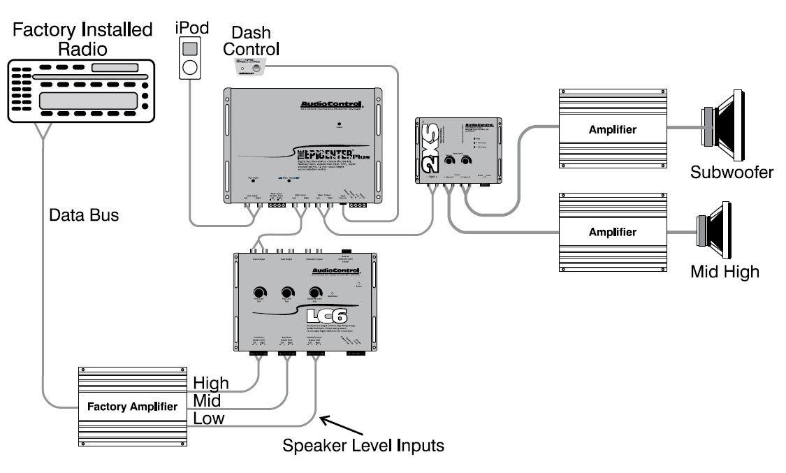
- Components: The diagram identifies the various components of the audio control epicenter, including amplifiers, speakers, crossovers, and signal processors.
- Connections: It outlines the electrical connections between these components, specifying the appropriate wire gauge, polarity, and shielding requirements.
- Signal Flow: The diagram illustrates the path of the audio signal through the system, ensuring optimal signal transfer and minimizing noise and distortion.
- Power Distribution: It indicates the power supply connections to each component, ensuring that they receive the correct voltage and current.
- Grounding: The diagram specifies the grounding points for each component, which is crucial for reducing noise and ensuring system stability.
- Troubleshooting: The diagram serves as a valuable tool for troubleshooting system issues, helping identify potential problems and their solutions.
- Optimization: By understanding the diagram, users can optimize their system’s performance by adjusting component settings and fine-tuning signal flow.
- Safety: Following the diagram’s instructions ensures that the system is wired correctly, minimizing the risk of electrical hazards.
- Documentation: The diagram provides a permanent record of the system’s wiring, which is useful for future reference and modifications.
These key aspects collectively contribute to the effective design and implementation of audio control epicenter wiring diagrams. They enable users to achieve optimal sound quality, system performance, and reliability while ensuring safety and facilitating troubleshooting and optimization.
Components
Within the context of an Audio Control Epicenter Wiring Diagram, the identification of components is a critical step that lays the foundation for a well-designed and functional audio system. The diagram serves as a blueprint, outlining the interconnections between various components, which include amplifiers, speakers, crossovers, and signal processors. Each component plays a specific role in the signal chain, affecting the overall sound quality and performance of the system.
Amplifiers, for instance, are responsible for increasing the power of the audio signal, driving the speakers to produce sound. Speakers, in turn, convert the electrical signal into audible sound waves. Crossovers divide the audio signal into different frequency bands, directing them to the appropriate speakers for optimal reproduction. Signal processors, such as equalizers and compressors, allow for further refinement of the sound, enhancing clarity, reducing distortion, and tailoring the sound to the specific acoustics of the listening environment.
By understanding the role and connections of each component within the Audio Control Epicenter Wiring Diagram, installers and enthusiasts can make informed decisions about component selection, placement, and optimization. This knowledge empowers them to achieve a cohesive and high-performing audio system that meets their desired sound quality and functionality.
Connections
Within the context of an Audio Control Epicenter Wiring Diagram, the specification of electrical connections plays a critical role in ensuring the proper operation and performance of the audio system. These connections define the pathways through which audio signals and power are transmitted between the various components, including amplifiers, speakers, crossovers, and signal processors.
The wire gauge, polarity, and shielding requirements specified in the diagram are essential considerations for maintaining signal integrity and preventing electrical hazards. The appropriate wire gauge ensures that the conductors can carry the required current without excessive voltage drop or power loss. Correct polarity connections ensure that the audio signal is maintained in phase, preventing phase cancellations and ensuring optimal sound quality. Proper shielding minimizes the effects of electromagnetic interference (EMI) and radio frequency interference (RFI), which can degrade the audio signal and introduce unwanted noise.
Real-life examples of the importance of proper electrical connections in an Audio Control Epicenter Wiring Diagram include:
- Using a wire gauge that is too thin can lead to voltage drop and power loss, resulting in reduced sound quality and potential damage to components.
- Incorrect polarity connections can cause phase cancellations, resulting in a loss of bass response and a compromised soundstage.
- Insufficient shielding can allow EMI and RFI to interfere with the audio signal, introducing noise and distortion.
Understanding the electrical connections specified in the Audio Control Epicenter Wiring Diagram empowers installers and enthusiasts to make informed decisions about the selection and installation of audio components. By following the diagram’s guidelines, they can ensure that the system is wired correctly, minimizing the risk of electrical hazards and optimizing sound quality.
In summary, the electrical connections outlined in the Audio Control Epicenter Wiring Diagram are critical for establishing a solid foundation for a well-functioning and high-performance audio system. Proper wire gauge, polarity, and shielding considerations ensure signal integrity, prevent electrical hazards, and maximize the listening experience.
Signal Flow
The relationship between signal flow and the Audio Control Epicenter Wiring Diagram is fundamental, as the diagram provides a visual representation of the signal path through the audio system. Understanding this signal flow is critical for optimizing sound quality and minimizing noise and distortion.
Within the diagram, the signal flow is meticulously outlined, indicating the direction and connections between components. This information enables installers and enthusiasts to:
- Identify potential signal loss or interference points, allowing for proper placement and shielding of components.
- Optimize the signal path by selecting the appropriate cables and connectors, ensuring minimal signal degradation.
- Troubleshoot system issues by isolating sections of the signal chain and identifying where signal degradation or noise is introduced.
Real-life examples of the importance of understanding signal flow within an Audio Control Epicenter Wiring Diagram include:
- Ground loops, which can introduce hum and noise into the audio system, can be eliminated by identifying and breaking the ground loop in the signal path.
- Proper placement of components, such as isolating power amplifiers from sensitive preamplifiers, can minimize electromagnetic interference and improve signal quality.
- The use of high-quality cables and connectors with low resistance and proper shielding can significantly reduce signal loss and distortion.
In summary, the signal flow outlined in the Audio Control Epicenter Wiring Diagram is a critical aspect of achieving optimal sound quality and system performance. Understanding this signal flow empowers installers and enthusiasts to make informed decisions about component selection, placement, and optimization, ultimately resulting in an immersive and enjoyable listening experience.
Power Distribution
Within the context of an Audio Control Epicenter Wiring Diagram, power distribution plays a pivotal role in ensuring that each component receives the necessary electrical power to function optimally. The diagram provides a comprehensive overview of the power supply connections, outlining the specific requirements for each component, including voltage, current, and grounding.
- Power Supply Selection: The diagram specifies the type and capacity of the power supply required for the system. This information is crucial for selecting a power supply that can meet the power demands of all the components without introducing noise or instability.
- Voltage Regulation: The diagram indicates the voltage requirements of each component, ensuring that they receive the correct voltage to operate efficiently. Proper voltage regulation prevents damage to components and ensures optimal performance.
- Current Capacity: The diagram specifies the current capacity of the power supply, which must be sufficient to meet the current demands of all the connected components. Inadequate current capacity can lead to voltage drops, power loss, and potential damage to components.
- Grounding: The diagram provides grounding instructions, which are essential for minimizing noise and ensuring system stability. Proper grounding establishes a common reference point for all components, preventing ground loops and other electrical issues.
Understanding and following the power distribution guidelines in the Audio Control Epicenter Wiring Diagram is critical for achieving a well-functioning and reliable audio system. Proper power distribution ensures that each component operates at its optimal level, resulting in improved sound quality, reduced noise, and extended component life.
Grounding
Within the context of an Audio Control Epicenter Wiring Diagram, grounding plays a critical role in maintaining a clean and stable audio signal, minimizing noise, and preventing system instability. The diagram provides precise instructions on the grounding points for each component, ensuring proper electrical connections and optimal system performance.
- Noise Reduction: Grounding establishes a common reference point for all components in the system, preventing ground loops and other electrical issues that can introduce hum, buzzing, and other unwanted noise into the audio signal.
- Improved Signal Quality: Proper grounding minimizes the effects of electromagnetic interference (EMI) and radio frequency interference (RFI), which can degrade the audio signal and introduce distortion.
- System Stability: Grounding provides a stable electrical environment for the system, preventing voltage fluctuations and other electrical hazards that can damage components or cause system instability.
- Safety: Grounding ensures that any electrical faults or surges are safely discharged, protecting both the equipment and the user from electrical shocks.
By following the grounding instructions specified in the Audio Control Epicenter Wiring Diagram, installers and enthusiasts can ensure that their audio system operates at its optimal level, delivering a clean, noise-free, and immersive listening experience.
Troubleshooting
Within the context of an Audio Control Epicenter Wiring Diagram, troubleshooting plays a critical role in maintaining a well-functioning and reliable audio system. The diagram serves as a valuable roadmap for identifying and resolving system issues, ensuring optimal performance and listening enjoyment.
The Audio Control Epicenter Wiring Diagram provides a comprehensive overview of the system’s electrical connections, making it easier to identify potential problems. By following the diagram’s instructions, installers and enthusiasts can systematically check connections, identify loose wires, and pinpoint faulty components.
Real-life examples of the practical applications of troubleshooting within an Audio Control Epicenter Wiring Diagram include:
- Identifying Ground Loops: Ground loops, which can introduce hum and noise into the audio system, can be identified and eliminated by analyzing the grounding connections specified in the diagram.
- Tracing Signal Loss: If a component is not receiving a signal, the diagram can be used to trace the signal path and identify any breaks or disconnections.
- Diagnosing Amplifier Issues: The diagram provides insights into the power distribution and grounding connections of amplifiers, aiding in the diagnosis and resolution of power-related issues.
Understanding how to troubleshoot using the Audio Control Epicenter Wiring Diagram empowers installers and enthusiasts to proactively maintain their audio systems, resolve issues quickly and effectively, and achieve optimal sound quality.
In summary, the troubleshooting capabilities provided by the Audio Control Epicenter Wiring Diagram are essential for maintaining a well-functioning and reliable audio system. By enabling the identification and resolution of system issues, the diagram empowers users to enjoy a hassle-free and immersive listening experience.
Optimization
The Audio Control Epicenter Wiring Diagram serves as a crucial foundation for optimizing an audio system’s performance. By comprehending the diagram’s intricacies, users gain the ability to make informed adjustments to component settings and fine-tune the signal flow, ultimately enhancing the overall listening experience.
The diagram provides a comprehensive overview of the system’s electrical connections and signal routing. This knowledge empowers users to:
- Adjust Component Settings: The diagram identifies each component’s adjustable parameters, allowing users to optimize settings such as crossover frequencies, equalization curves, and amplifier gain to achieve the desired sound characteristics.
- Fine-tune Signal Flow: By understanding the signal path, users can identify and address potential bottlenecks or inefficiencies. This enables them to optimize cable lengths, minimize signal loss, and ensure proper impedance matching for optimal signal transfer.
Real-life examples of optimization techniques enabled by the Audio Control Epicenter Wiring Diagram include:
- Speaker Placement and Crossover Adjustment: The diagram guides users in positioning speakers for optimal sound dispersion and adjusting crossover frequencies to ensure smooth transitions between drivers.
- Equalization: The diagram provides insights into the system’s frequency response, enabling users to apply equalization adjustments to compensate for room acoustics or personal preferences.
- Amplifier Gain and Impedance Matching: The diagram helps users determine the appropriate amplifier gain settings and ensure proper impedance matching between components to minimize distortion and maximize power efficiency.
In summary, the Audio Control Epicenter Wiring Diagram empowers users to optimize their audio systems by providing a deep understanding of the system’s electrical connections and signal flow. Through informed adjustments to component settings and fine-tuning of the signal path, users can achieve enhanced sound quality, improved performance, and a truly immersive listening experience.
Safety
The Audio Control Epicenter Wiring Diagram plays a critical role in ensuring the safety of the audio system by providing clear instructions on how to wire the components correctly. Electrical hazards, such as short circuits or fires, can occur if the system is not wired properly, potentially damaging the equipment or even causing injury to users.
By following the diagram’s instructions, users can ensure that the system is wired according to industry standards and safety regulations. The diagram specifies the correct wire gauge, connectors, and grounding requirements, which are essential for preventing electrical hazards.
Real-life examples of the importance of safety in Audio Control Epicenter Wiring Diagrams include:
- Using the wrong wire gauge can lead to overheating and potential fire hazards.
- Improper grounding can result in electrical shocks or damage to equipment.
- Loose connections can cause arcing and electrical fires.
Understanding the safety guidelines in the Audio Control Epicenter Wiring Diagram is crucial for ensuring a safe and reliable audio system. By following the diagram’s instructions, users can minimize the risk of electrical hazards and enjoy their audio system with peace of mind.
Documentation
The Audio Control Epicenter Wiring Diagram serves as a vital form of documentation, providing a comprehensive and permanent record of the system’s electrical connections. This documentation plays a crucial role in maintaining, troubleshooting, and modifying the audio system effectively throughout its lifespan.
By having a detailed wiring diagram, users can easily refer back to the system’s configuration, identify specific connections, and trace signal flow. This information becomes invaluable when troubleshooting issues, as it allows users to pinpoint potential problems and identify the affected components quickly and accurately.
Real-life examples of the practical applications of documentation within an Audio Control Epicenter Wiring Diagram include:
- Future Modifications: When making changes or upgrades to the system, the wiring diagram serves as a roadmap, guiding users through the necessary re-wiring and ensuring that all connections are made correctly.
- Troubleshooting: The diagram aids in identifying and resolving electrical issues by providing a visual representation of the system’s connections, allowing users to trace signal paths and pinpoint potential faults.
Understanding the importance of documentation in the Audio Control Epicenter Wiring Diagram empowers users to maintain and modify their audio systems with confidence, ensuring optimal performance and longevity.
In summary, the documentation provided by the Audio Control Epicenter Wiring Diagram is a critical component, offering a permanent record of the system’s wiring. This documentation facilitates future modifications, simplifies troubleshooting, and enhances the overall user experience, contributing to a well-functioning and enjoyable audio system.


Related Posts


