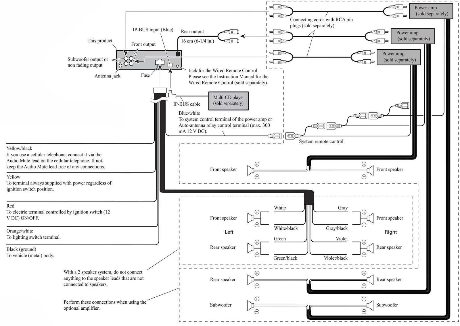
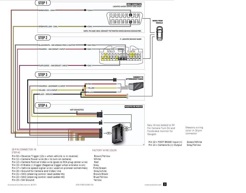
An ASWC-1 wiring diagram is a detailed schematic that illustrates the connections and components within an Automotive Steering Wheel Control (ASWC) system. It specifies the wiring layout, pinouts, and signal paths, enabling technicians and installers to correctly integrate the ASWC module with a vehicle’s audio system and steering wheel controls.
ASWC-1 wiring diagrams are essential for ensuring proper functionality and preventing electrical issues. They help technicians identify and troubleshoot any wiring discrepancies or faults, thereby enhancing the driving experience and ensuring the safety of vehicle occupants. A key historical development in ASWC-1 wiring diagrams was the adoption of standardized color codes and connectors, which simplified installation and reduced the risk of errors.
The upcoming article will further delve into the complexities of ASWC-1 wiring diagrams, exploring advanced features, industry-specific applications, and emerging technologies in this field, providing invaluable insights for professionals involved in automotive electronics and wiring systems.
Understanding the essential aspects of ASWC-1 wiring diagrams is crucial for professionals in the automotive electronics industry. These diagrams provide a comprehensive blueprint for the electrical connections and components within an Automotive Steering Wheel Control system, ensuring proper functionality and safety. Let’s explore nine key aspects of ASWC-1 wiring diagrams:
- Color Coding: Standardized color codes simplify wire identification and reduce installation errors.
- Connector Types: Specific connectors ensure secure and reliable connections between components.
- Pinouts: Diagrams clearly indicate the pinouts for each connector, guiding proper wire connections.
- Signal Paths: Diagrams trace the signal flow through the system, facilitating troubleshooting.
- Grounding: Proper grounding is essential for system stability and noise reduction.
- Shielding and Isolation: Shielding and isolation techniques minimize electrical interference and ensure signal integrity.
- Component Identification: Diagrams provide clear identification of all components, including resistors, capacitors, and transistors.
- Industry Standards: ASWC-1 wiring diagrams adhere to industry standards, ensuring compatibility with various vehicle models.
- Safety Features: Diagrams highlight safety features such as overcurrent protection and fault detection.
These aspects are interconnected and crucial for the effective design, installation, and maintenance of ASWC-1 systems. They enable technicians to interpret and troubleshoot wiring diagrams accurately, ensuring optimal performance and safety. Understanding these aspects provides a solid foundation for professionals working with automotive electronics and wiring systems.
Color Coding
Within the intricate landscape of ASWC-1 wiring diagrams, color coding emerges as a fundamental aspect, streamlining wire identification and minimizing installation errors. Standardized color codes assign unique hues to specific wire functions, enabling technicians to quickly trace and connect wires, reducing the likelihood of incorrect connections.
- Function Identification: Color coding facilitates rapid identification of wire functions, such as power, ground, audio signals, and illumination. Each color represents a specific purpose, simplifying wire tracing and preventing mix-ups.
- Industry Standards: Adherence to industry-established color codes ensures consistency across different ASWC-1 systems and vehicle models. This standardization eliminates confusion and allows technicians to work seamlessly on various vehicles.
- Reduced Errors: Standardized color coding minimizes the risk of installation errors by providing a clear visual distinction between wires. This reduces the likelihood of accidental connections or shorts, enhancing system reliability and safety.
- Simplified Troubleshooting: In the event of system malfunctions, color coding aids in troubleshooting by enabling technicians to quickly isolate faulty wires. By following the color-coded paths, they can pinpoint the source of the issue and implement targeted repairs.
In conclusion, color coding in ASWC-1 wiring diagrams plays a pivotal role in enhancing system integrity and installation efficiency. Standardized color codes provide a universal language for wire identification, reducing errors, expediting troubleshooting, and ensuring the safety and reliability of automotive steering wheel control systems.
Connector Types
Within the intricate network of an ASWC-1 wiring diagram, connector types play a crucial role in establishing secure and dependable connections between various components. These specialized connectors are designed to meet specific requirements, ensuring optimal signal transmission, preventing loose connections, and safeguarding against environmental factors.
- Types of Connectors: ASWC-1 wiring diagrams incorporate a range of connector types, each tailored to specific functions. Common types include Molex connectors, JST connectors, and Delphi connectors, each featuring unique designs and pin configurations.
- Secure Connections: The connectors employed in ASWC-1 wiring diagrams are engineered to provide secure mechanical connections between components. They utilize locking mechanisms, such as clips or latches, to prevent accidental disconnections, ensuring uninterrupted signal transmission and system stability.
- Environmental Protection: Many connectors used in ASWC-1 wiring diagrams are designed to withstand harsh environmental conditions. They incorporate weather-resistant materials, seals, and gaskets to protect against moisture, dust, and extreme temperatures, ensuring reliable operation in diverse environments.
- Signal Integrity: The connectors utilized in ASWC-1 wiring diagrams are meticulously designed to minimize signal loss and distortion. They feature low contact resistance and high-quality materials to maintain signal integrity, preserving the accuracy and clarity of data transmission.
In summary, connector types play a critical role in ASWC-1 wiring diagrams by ensuring secure connections, protecting against environmental factors, and preserving signal integrity. These specialized connectors are essential for maintaining optimal system performance, safety, and reliability in automotive steering wheel control applications.
Pinouts
Within the intricate schematics of ASWC-1 wiring diagrams, pinouts emerge as a fundamental component, providing a roadmap for precise wire connections between various system components. These diagrams meticulously specify the pin assignments for each connector, ensuring the proper flow of electrical signals and preventing misconnections.
Pinouts serve as a critical guide for technicians and installers, enabling them to accurately identify the designated pin on a connector that corresponds to a specific wire or signal. By adhering to the pinout specifications, they can establish secure and reliable connections, preventing short circuits, malfunctions, and potential safety hazards.
For instance, in an ASWC-1 system, the pinout diagram might indicate that pin 1 on connector X is designated for the ground connection, while pin 5 is for the power supply. By meticulously following these pinout instructions, technicians can ensure that the ground wire is connected to the correct pin, preventing electrical shorts and maintaining system stability.
Moreover, pinouts play a vital role in troubleshooting and repair scenarios. By referencing the pinout diagram, technicians can quickly identify the specific pin associated with a malfunctioning component. This allows for targeted troubleshooting, reducing downtime and minimizing the need for extensive system overhauls.
In summary, pinouts in ASWC-1 wiring diagrams are indispensable for establishing proper wire connections, ensuring system integrity, and facilitating efficient troubleshooting. Their precise specifications guide technicians towards accurate and reliable installations, contributing to the overall safety and functionality of automotive steering wheel control systems.
Signal Paths
Within the intricate landscape of ASWC-1 wiring diagrams, signal paths emerge as a crucial aspect, providing a clear roadmap for the flow of electrical signals throughout the system. These diagrams meticulously trace the pathways of signals from their source to their destination, enabling technicians to visualize and troubleshoot signal-related issues.
- Signal Origin and Destination: ASWC-1 wiring diagrams clearly indicate the origin and destination of each signal, allowing technicians to understand the direction of signal flow. This knowledge is essential for tracing signal paths and identifying potential disruptions.
- Component Interactions: The diagrams illustrate how different components interact through signal exchange. Technicians can visualize how signals are processed, modified, and transmitted between modules, switches, and sensors.
- Signal Integrity: ASWC-1 wiring diagrams highlight potential sources of signal interference, such as electromagnetic noise or ground loops. By understanding these factors, technicians can implement appropriate shielding or isolation techniques to maintain signal integrity.
- Troubleshooting Guide: Signal path diagrams serve as a valuable troubleshooting guide. By analyzing signal flow and identifying potential failure points, technicians can pinpoint the root cause of malfunctions and implement targeted repairs.
In summary, signal paths in ASWC-1 wiring diagrams play a fundamental role in ensuring proper system operation and efficient troubleshooting. These diagrams empower technicians with a deep understanding of signal flow, enabling them to diagnose and resolve issues quickly and effectively, contributing to the overall reliability and safety of automotive steering wheel control systems.
Grounding
Within the intricate web of ASWC-1 wiring diagrams, grounding emerges as a cornerstone for maintaining system stability and minimizing noise interference. Proper grounding practices ensure a stable electrical reference point, preventing voltage fluctuations and ensuring optimal signal transmission.
- Chassis Grounding: ASWC-1 wiring diagrams specify designated chassis grounding points, which provide a low-resistance path for electrical current to flow back to the vehicle’s battery. This prevents the accumulation of stray voltage on system components, enhancing stability and preventing potential damage.
- Component Grounding: Each electrical component within the ASWC-1 system requires proper grounding to function correctly. Wiring diagrams indicate the specific grounding points for switches, modules, and sensors, ensuring that they share a common electrical reference.
- Noise Reduction: Proper grounding minimizes noise interference by providing a low-impedance path for unwanted electrical signals to dissipate. This reduces electromagnetic interference (EMI) and ensures clean signal transmission, improving system performance and audio quality.
- Safety: Adequate grounding also plays a crucial role in ensuring system safety. By providing a defined path for electrical current to flow, grounding prevents voltage spikes and electrical hazards, protecting both the system and its users.
In conclusion, grounding is an essential aspect of ASWC-1 wiring diagrams, ensuring system stability, noise reduction, and safety. By adhering to proper grounding practices, technicians can optimize system performance, prevent malfunctions, and maintain the integrity of automotive steering wheel control systems.
Shielding and Isolation
Within the intricate realm of ASWC-1 wiring diagrams, shielding and isolation techniques emerge as crucial safeguards against electrical interference and signal degradation. These measures ensure the integrity of electrical signals, preventing disruptions and maintaining optimal system performance.
- Electromagnetic Interference (EMI) Shielding: EMI shielding involves enclosing sensitive components or wires within conductive materials to block electromagnetic radiation. This prevents external electrical noise from disrupting signal transmission, ensuring reliable data communication.
- Ground Isolation: Ground isolation techniques employ isolation transformers or optocouplers to create electrical isolation between different parts of the system. This prevents ground loops and potential differences from interfering with signal integrity.
- Twisted Pair Cabling: Twisted pair cabling consists of two insulated wires twisted together. This configuration minimizes electromagnetic interference by canceling out induced noise from adjacent wires, improving signal quality.
- Fiber Optic Cables: Fiber optic cables transmit data using light pulses instead of electrical signals. This eliminates electrical interference completely, providing exceptional signal integrity and immunity to electromagnetic noise.
In conclusion, shielding and isolation techniques play a critical role in ASWC-1 wiring diagrams by safeguarding against electrical interference and ensuring signal integrity. By implementing these measures, automotive engineers can design robust and reliable steering wheel control systems that operate seamlessly in diverse electrical environments.
Component Identification
Within the intricate schematics of ASWC-1 wiring diagrams, component identification plays a pivotal role in ensuring proper system operation and maintenance. These diagrams meticulously label and identify all electrical components, including resistors, capacitors, and transistors, providing a clear roadmap for technicians and installers.
- Precise Component Identification: ASWC-1 wiring diagrams utilize standardized symbols and notations to precisely identify each component. This ensures that technicians can easily recognize and locate specific components, even in complex systems.
- Simplified Troubleshooting: Accurate component identification is crucial for efficient troubleshooting. By quickly identifying faulty components, technicians can pinpoint the root cause of system malfunctions and implement targeted repairs, reducing downtime and maintenance costs.
- Component Specifications: Wiring diagrams often include detailed specifications for each component, such as resistance values for resistors, capacitance values for capacitors, and transistor types. This information is essential for ensuring proper component selection and replacement.
- Circuit Analysis: Component identification enables technicians to analyze circuit behavior and identify potential issues. By understanding the function and interconnections of each component, they can proactively identify and address potential failure points.
In conclusion, component identification in ASWC-1 wiring diagrams is a fundamental aspect that facilitates accurate system assembly, efficient troubleshooting, and comprehensive circuit analysis. By providing clear and precise identification of electrical components, these diagrams empower technicians to maintain and repair ASWC systems effectively, ensuring optimal performance and safety.
Industry Standards
Within the realm of ASWC-1 wiring diagrams, industry standards play a pivotal role in ensuring compatibility and seamless integration across different vehicle models. By adhering to established standards, manufacturers can design and produce ASWC systems that are universally compatible, simplifying installation, enhancing performance, and promoting safety.
- Standardized Connectors and Pinouts: Industry standards define specific connectors and pinout configurations for ASWC systems. This ensures that steering wheel controls and audio systems from different manufacturers can be connected and interfaced without compatibility issues, eliminating the need for custom wiring or adapters.
- Electrical Signal Protocols: ASWC-1 wiring diagrams adhere to standardized electrical signal protocols, such as CAN (Controller Area Network) or LIN (Local Interconnect Network). These protocols govern the communication between different components within the ASWC system, ensuring reliable and efficient data transmission.
- Safety Regulations: Industry standards incorporate safety regulations and guidelines to ensure that ASWC systems operate safely and reliably. These regulations cover aspects such as electrical isolation, fault detection, and system redundancy, minimizing potential hazards and protecting vehicle occupants.
- Quality Assurance: By adhering to industry standards, manufacturers are held accountable for maintaining high levels of quality and reliability in their ASWC systems. This includes rigorous testing and validation procedures to ensure that the systems meet performance and safety requirements.
In conclusion, industry standards for ASWC-1 wiring diagrams are essential for ensuring compatibility, safety, and ease of installation across various vehicle models. By adhering to these standards, manufacturers can create interoperable systems that enhance the driving experience, promote safety, and simplify maintenance procedures for automotive technicians.
Safety Features
In the realm of Automotive Steering Wheel Control (ASWC)-1 wiring diagrams, safety features hold paramount importance, ensuring the reliable and hazard-free operation of vehicle systems. These diagrams meticulously incorporate specific safety measures to protect against electrical faults, component damage, and potential hazards to occupants.
- Overcurrent Protection: Wiring diagrams highlight the inclusion of overcurrent protection devices, such as fuses or circuit breakers, to safeguard electrical circuits from excessive current flow. This prevents overheating, component damage, and potential fires.
- Fault Detection: Diagrams indicate fault detection mechanisms that monitor system parameters and trigger warning signals or corrective actions in the event of abnormal conditions. These features enhance system reliability and enable timely intervention to prevent cascading failures.
- Ground Fault Protection: Wiring diagrams specify proper grounding techniques and protections to minimize the risk of electrical shocks and ensure the safe operation of electronic components. Ground fault interrupters may be included to detect and isolate faults in the grounding system.
- Electromagnetic Interference (EMI) Mitigation: Diagrams address EMI mitigation strategies, such as shielding and filtering techniques, to minimize electrical noise and interference that could disrupt system functionality or compromise safety.
These safety features, meticulously detailed in ASWC-1 wiring diagrams, provide multiple layers of protection for both the system and vehicle occupants. By adhering to industry standards and incorporating these safety measures, manufacturers prioritize the integrity and reliability of automotive steering wheel control systems, contributing to a safer and more enjoyable driving experience.


Related Posts


