An AC contactor wiring diagram illustrates the electrical connections and configuration of an alternating current (AC) contactor, a switch that controls the flow of high-power electrical currents. A typical example is the wiring of a three-phase motor contactor, which connects a motor to a power source, enabling remote control and protection from overloads.
AC contactor wiring diagrams are crucial for ensuring safe and efficient operation of electrical systems. They provide a visual representation of the electrical connections and facilitate troubleshooting and maintenance. A key historical development was the introduction of IEC 60617-4-1 in 1997, which standardized the symbols and conventions used in contactor wiring diagrams.
This article will delve into the components of an AC contactor wiring diagram, explain the electrical connections, and discuss factors to consider when designing and installing contactor circuits to ensure reliable and efficient operation.
Ac contactor wiring diagrams are essential for the safe and efficient operation of electrical systems. They provide a visual representation of the electrical connections and facilitate troubleshooting and maintenance. The key aspects of an AC contactor wiring diagram include:
- Circuit protection
- Control circuit
- Contactor coil
- Load circuit
- Main contacts
- Auxiliary contacts
- Terminal markings
- Power source
- Wire sizing
- IEC standards
These aspects are interconnected and must be considered together when designing and installing contactor circuits. For example, the wire sizing must be appropriate for the current carrying capacity of the contactor and the load. The circuit protection devices must be selected to protect the contactor and the load from overloads and short circuits. The control circuit must be designed to provide reliable operation of the contactor coil. By considering all of these aspects, engineers can ensure that AC contactor wiring diagrams are accurate, safe, and efficient.
Circuit protection
Circuit protection is a critical component of any electrical system, and AC contactor wiring diagrams are no exception. Circuit protection devices, such as fuses and circuit breakers, are used to protect the contactor and the load from overloads and short circuits. Without proper circuit protection, the contactor could overheat and fail, which could lead to a fire or other dangerous situation.
There are a number of different types of circuit protection devices that can be used in AC contactor wiring diagrams. The most common type is the fuse. Fuses are relatively inexpensive and easy to replace, and they provide good protection against overloads and short circuits. However, fuses can also be slow to blow, which can lead to damage to the contactor or the load if a fault occurs.
Circuit breakers are another type of circuit protection device that can be used in AC contactor wiring diagrams. Circuit breakers are more expensive than fuses, but they offer a number of advantages. Circuit breakers are faster acting than fuses, and they can be reset after they have tripped, which makes them more convenient to use. Additionally, circuit breakers can be used to protect against both overloads and short circuits.
The type of circuit protection device that is used in an AC contactor wiring diagram will depend on the specific application. However, it is important to always use a circuit protection device that is rated for the current carrying capacity of the contactor and the load.
By understanding the connection between circuit protection and AC contactor wiring diagrams, engineers can design and install safe and reliable electrical systems.
Control circuit
In the context of an AC contactor wiring diagram, the control circuit is responsible for initiating and maintaining the contactor’s operation. It provides the electrical pathway for the low-power signals that energize the contactor coil, which in turn activates the main contacts to control the flow of high power to the load.
-
Control voltage
The control voltage is the voltage level used to energize the contactor coil. It is typically a low voltage, such as 12V or 24V, and is derived from a separate control transformer or power supply. -
Control switch
The control switch is a manually operated device that initiates the contactor’s operation. It is connected in series with the contactor coil and provides the path for the control voltage to energize the coil. -
Interlock contacts
Interlock contacts are auxiliary contacts that are mechanically linked to the contactor’s main contacts. They are used to ensure that the contactor cannot be energized unless the main contacts are closed. -
Timer relays
Timer relays are used to delay the operation of the contactor for a predetermined period of time. They are typically used to prevent the contactor from being energized too quickly, which can cause damage to the contactor or the load.
The control circuit is a critical part of an AC contactor wiring diagram, as it ensures that the contactor operates safely and reliably. By understanding the different components of the control circuit and their functions, engineers can design and install contactor circuits that meet the specific requirements of their applications.
Contactor coil
Within the intricate network of an AC contactor wiring diagram, the contactor coil plays a pivotal role, acting as the gatekeeper to the flow of electrical power. It is a captivating interplay of magnetic forces and electrical impulses, where a small trickle of control current orchestrates the switching of high-power loads.
-
Coil voltage
The coil voltage determines the amount of electrical energy required to energize the coil, ultimately affecting its magnetic strength and contactor operation. Proper selection of coil voltage is crucial to ensure compatibility with the control circuit and reliable contactor performance. -
Coil terminals
Coil terminals serve as the electrical entry points, providing a secure connection between the control circuit and the coil windings. These terminals facilitate the flow of current, energizing the coil to generate the magnetic field essential for contactor operation. -
Coil insulation
Coil insulation plays a vital role in preventing electrical breakdown and short circuits. It ensures that the coil windings are electrically isolated from the contactor frame and other components, maintaining the integrity of the control circuit and protecting against hazardous situations. -
Coil protection
Coil protection measures safeguard the coil from electrical surges and overloads that could damage its delicate windings. This can involve the use of surge suppressors or transient voltage suppressors, ensuring the longevity and reliability of the contactor coil.
In summary, the contactor coil, with its intricate interplay of coil voltage, terminals, insulation, and protection mechanisms, forms the very heart of an AC contactor wiring diagram. Understanding these facets is paramount for electrical engineers and technicians seeking to design, install, and maintain efficient and safe contactor circuits, ensuring the smooth flow of electrical power in various industrial and commercial applications.
Load circuit
Within the intricate network of an AC contactor wiring diagram, the load circuit plays a pivotal role, carrying the electrical power to the intended destination, be it a motor, lighting system, or other electrical device. Understanding its components and their functions is paramount for ensuring the safe and efficient operation of AC contactor circuits.
-
Load terminals
Load terminals serve as the electrical interface between the contactor and the load, providing a secure connection for the flow of electrical current. Proper selection of load terminals is crucial, considering factors such as current carrying capacity, voltage rating, and type of load being connected.
-
Load wiring
Load wiring encompasses the conductors that carry electrical current from the contactor to the load. Careful attention must be paid to wire sizing, insulation, and routing to ensure compliance with electrical codes and safe operation of the circuit.
-
Overload protection
Overload protection measures, such as thermal overload relays or circuit breakers, are incorporated into the load circuit to safeguard against excessive current flow that could damage the load or cause electrical hazards. Selecting the appropriate overload protection devices is critical for ensuring reliable and protected operation.
-
Power factor correction
In AC circuits, power factor correction techniques may be employed to improve the efficiency of the load circuit by reducing reactive power consumption. This can involve the use of capacitors or other power factor correction devices, leading to energy savings and improved system performance.
In conclusion, the load circuit in an AC contactor wiring diagram plays a crucial role in delivering electrical power to the intended load while ensuring safety and efficiency. Understanding the various components and their functions empowers electrical engineers and technicians to design, install, and maintain reliable and optimized contactor circuits, meeting the demands of diverse industrial and commercial applications.
Main contacts
Within the intricate network of an AC contactor wiring diagram, the main contacts assume a central role, acting as the primary pathway for electrical current to flow from the power source to the load. Their significance stems from the crucial function they perform in controlling and distributing electrical power in various industrial and commercial applications.
The main contacts are designed to carry high currents, often exceeding hundreds of amperes, and are constructed using robust materials such as silver alloys or copper alloys to ensure reliable conduction and minimal contact resistance. They are typically arranged in a double-break configuration, providing increased safety and redundancy by simultaneously breaking both poles of the circuit.
Real-life examples of main contacts in AC contactor wiring diagrams can be found in numerous electrical systems, including motor control circuits, lighting systems, and power distribution panels. In motor control circuits, the main contacts are responsible for switching the motor on and off, as well as reversing its direction of rotation if required. In lighting systems, the main contacts control the flow of current to lighting fixtures, allowing for centralized control and efficient energy management.
Understanding the connection between main contacts and AC contactor wiring diagrams is essential for electrical engineers and technicians involved in the design, installation, and maintenance of electrical systems. Proper selection and configuration of main contacts ensure safe and efficient operation of the circuit, preventing electrical hazards, minimizing downtime, and optimizing energy consumption. Bying this critical component of AC contactor wiring diagrams, professionals can contribute to the reliability and performance of electrical systems across various industries.
Auxiliary contacts
Within the intricate landscape of AC contactor wiring diagrams, auxiliary contacts emerge as versatile and indispensable components. These auxiliary contacts, also known as helper contacts or interlock contacts, extend the functionality of AC contactors beyond their primary role of controlling high-power circuits.
- Indication: Auxiliary contacts provide valuable feedback on the status of the main contacts. They can be wired to indicate whether the main contacts are open or closed, aiding in troubleshooting and monitoring circuit conditions.
- Interlocking: Auxiliary contacts can be interlocked with other contactors or devices to create interlocking circuits. This interlocking prevents unsafe or unintended sequences of operation, enhancing safety and preventing equipment damage.
- Multiple circuits control: Auxiliary contacts allow for the control of multiple circuits with a single contactor. By connecting auxiliary contacts in parallel with other devices, it becomes possible to simultaneously control several circuits, simplifying wiring and reducing the number of contactors required.
- Signaling: Auxiliary contacts can be utilized for signaling purposes. They can be wired to activate alarms, indicator lights, or other devices, providing remote indication of contactor status or circuit conditions.
In essence, auxiliary contacts serve as auxiliary switches within the AC contactor wiring diagram. They extend the capabilities of the contactor, enabling additional control, monitoring, and interlocking functions. Understanding the role and applications of auxiliary contacts is crucial for electrical engineers and technicians involved in the design, installation, and maintenance of AC contactor circuits, contributing to the safe, efficient, and reliable operation of electrical systems in various industrial and commercial settings.
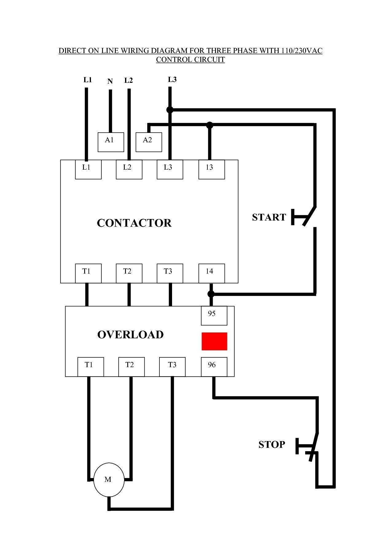
Terminal markings
In the realm of AC contactor wiring diagrams, terminal markings hold significant importance, providing crucial information for the identification, connection, and maintenance of electrical circuits. These markings serve as a roadmap, guiding electricians and engineers in ensuring the proper functioning and safety of electrical systems.
- Phase terminals: Labeled as L1, L2, L3, these terminals establish the connection to the three phases of an AC power source, providing the contactor with the electrical energy it needs to operate.
- Load terminals: Typically marked as T1, T2, T3, these terminals represent the points of connection for the electrical load, such as a motor or lighting system. Proper wiring of these terminals ensures that the load receives the necessary power.
- Coil terminals: Designated as A1 and A2, these terminals are crucial for energizing the contactor coil, which in turn engages the main contacts and initiates the flow of power to the load.
- Auxiliary contact terminals: Often labeled as 13-14 and 21-22, these terminals provide access to the auxiliary contacts of the contactor. Auxiliary contacts are used for various purposes, such as interlocking, signaling, and control of additional circuits.
Understanding terminal markings is paramount for accurate electrical installations and troubleshooting. Miswiring or incorrect identification can lead to malfunctioning circuits, safety hazards, and costly downtime. By adhering to established conventions and industry standards, electrical professionals can ensure the safe and efficient operation of AC contactor circuits, contributing to the reliability and performance of electrical systems.
Power source
In the realm of AC contactor wiring diagrams, the power source stands as an indispensable component, providing the electrical energy that drives the operation of contactors and, by extension, the connected loads. Understanding the connection between power sources and AC contactor wiring diagrams is crucial for the safe and efficient design, installation, and maintenance of electrical systems.
The power source serves as the for the electrical circuit, supplying the voltage and current necessary to energize the contactor coil. Without a reliable power source, the contactor remains inactive, and the load remains isolated from the electrical network. The type of power source used depends on the specific application and can range from single-phase or three-phase AC power to DC power sources such as batteries.
In real-life applications, power sources for AC contactor wiring diagrams can be found in various forms, including electrical outlets, transformers, generators, and solar panels. Each type of power source has its own characteristics, advantages, and considerations, which must be carefully evaluated during the design process. For instance, in industrial settings, three-phase AC power is commonly used to power high-power motors and machinery, while in remote locations, solar panels may provide a sustainable and reliable source of electricity.
Understanding the connection between power sources and AC contactor wiring diagrams empowers electrical professionals to make informed decisions regarding the selection, installation, and maintenance of electrical systems. By ensuring a reliable and appropriate power source, they contribute to the safe, efficient, and reliable operation of electrical circuits, supporting the smooth functioning of industries, businesses, and our daily lives.
Wire sizing
In the intricate tapestry of AC contactor wiring diagrams, wire sizing emerges as a crucial aspect, dictating the electrical safety, efficiency, and reliability of the entire system. It involves carefully selecting the appropriate wire gauge and type for each segment of the circuit, ensuring that the wires can safely carry the intended current while minimizing power losses.
- Current carrying capacity: Each wire has a maximum current carrying capacity, which must not be exceeded to prevent overheating and potential fire hazards. Wire sizing calculations consider the load current, ambient temperature, and wire material to ensure safe operation.
- Voltage drop: Wires exhibit resistance, which causes a voltage drop along their length. Proper wire sizing minimizes voltage drop, ensuring that the load receives the required voltage for optimal performance.
- Wire type: AC contactor wiring diagrams may specify the type of wire to be used, such as copper or aluminum. The choice of wire type depends on factors like current carrying capacity, flexibility, and cost considerations.
- Wire gauge: Wire gauge refers to the diameter of the wire, with lower gauge numbers indicating thicker wires. Proper wire gauge selection ensures that the wire can handle the required current without overheating or voltage drop issues.
Understanding the principles of wire sizing is essential for electrical engineers and technicians involved in the design, installation, and maintenance of AC contactor circuits. By carefully considering the current carrying capacity, voltage drop, wire type, and wire gauge, they can ensure the safe and efficient operation of electrical systems, avoiding potential hazards and optimizing system performance.
IEC standards
In the domain of electrical engineering, IEC standards hold a pivotal role in ensuring the safety, reliability, and interoperability of electrical systems and components. These standards, developed and published by the International Electrotechnical Commission (IEC), provide a comprehensive framework of guidelines and specifications for the design, manufacture, testing, and operation of electrical equipment.
Within the context of AC contactor wiring diagrams, IEC standards serve as a critical foundation, establishing a common language and set of best practices for electrical professionals worldwide. By adhering to IEC standards, engineers and technicians can ensure that AC contactor wiring diagrams are accurate, consistent, and compliant with safety regulations.
Real-life examples of IEC standards in AC contactor wiring diagrams include the designation of terminal markings, the specification of wire sizes and types, and the definition of contactor coil voltages and currents. These standards help to ensure that contactors are wired correctly, providing reliable and safe operation. Furthermore, IEC standards facilitate the exchange of wiring diagrams between different manufacturers and across international borders, promoting collaboration and reducing the risk of errors.
Understanding the connection between IEC standards and AC contactor wiring diagrams is essential for electrical professionals involved in the design, installation, and maintenance of electrical systems. By adhering to IEC standards, they can contribute to the safety, efficiency, and reliability of electrical installations, ensuring the smooth functioning of industries, businesses, and our daily lives.


Related Posts


