An air conditioning unit wiring diagram is a set of detailed instructions that shows how to connect the electrical components of an air conditioner. This diagram includes information on the voltage, amperage, and wire gauge required for each component. With air conditioning becoming widespread in homes and commercial buildings, these wiring diagrams are crucial to ensure the safe and proper installation of these units.
Wiring diagrams play a critical role in ensuring the safe and efficient operation of air conditioning units. One key historical development was the standardization of these diagrams, ensuring consistency in their design and making it easier for technicians to understand and troubleshoot issues. This standardization has significantly contributed to the widespread adoption and reliability of air conditioning systems.
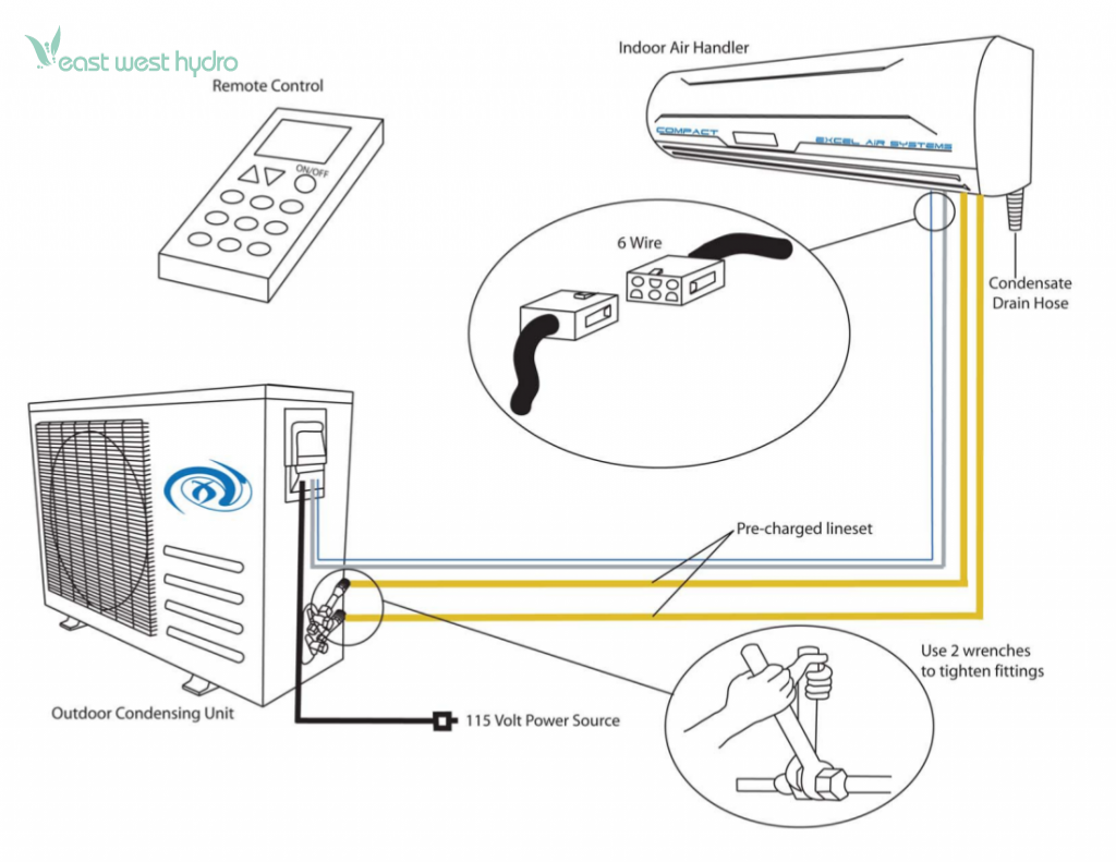
This article will explore the essential components of an A/C unit wiring diagram and provide a comprehensive guide to interpreting and utilizing these diagrams during installation and maintenance.
An A/C Wiring Diagram serves as a crucial guide for understanding the electrical connections within an air conditioning unit. Identifying the key aspects of these diagrams is essential for proper installation, maintenance, and troubleshooting. Here are nine essential aspects to consider:
- Circuit Breaker: Safety device protecting against electrical overloads.
- Condenser: Releases heat absorbed from the indoor unit.
- Control Panel: Regulates the unit’s operation and settings.
- Electrical Wiring: Conducts electricity between components.
- Evaporator Coil: Absorbs heat from the indoor air.
- Fan Motor: Circulates air over the evaporator and condenser coils.
- Refrigerant Lines: Carry refrigerant between the indoor and outdoor units.
- Run Capacitor: Helps start and run the compressor.
- Thermostat: Senses room temperature and controls the unit’s operation.
Understanding these aspects is crucial for electricians and HVAC technicians. A circuit breaker prevents electrical fires by tripping when too much current flows through the system. The condenser releases heat outside the building, while the evaporator coil absorbs heat inside. The control panel allows users to adjust settings and monitor the unit’s performance. Electrical wiring must meet code requirements to ensure safe operation. The fan motor circulates air, aiding in heat transfer. Refrigerant lines transport refrigerant, the substance that absorbs and releases heat. The run capacitor provides extra power to start the compressor. Finally, the thermostat maintains the desired indoor temperature by controlling the unit’s operation.
Circuit Breaker
Within the intricate network of an A/C unit wiring diagram, the circuit breaker stands as a crucial safeguard against electrical hazards. Its primary function is to prevent electrical overloads and potential fires by automatically interrupting the flow of electricity when it exceeds a predetermined safe level.
- Function: Monitors electrical current and trips to break the circuit when the current exceeds a safe threshold.
- Types: Various types exist, including thermal-magnetic breakers that respond to heat and magnetic breakers that respond to sudden current surges.
- Location: Typically installed in the electrical panel, providing easy access for resetting after tripping.
- Importance: Prevents damage to electrical components, reduces the risk of electrical fires, and ensures the safety of occupants.
The circuit breaker acts as a vigilant guardian, constantly monitoring the electrical flow within the A/C unit wiring diagram. Its presence ensures that any abnormal or excessive electrical conditions are swiftly addressed, safeguarding the integrity of the system and the well-being of those around it.
Condenser
In the intricate network of an A/C unit wiring diagram, the condenser occupies a pivotal position as the component responsible for releasing heat absorbed from the indoor unit. Its efficient operation is crucial for maintaining a comfortable indoor environment and ensuring the overall performance of the air conditioning system.
- Heat Transfer: The primary function of the condenser is to transfer heat from the refrigerant to the outdoor air. This heat exchange process is essential for the cooling cycle, as it allows the refrigerant to return to a liquid state and complete its circuit.
- Components: Key components of the condenser include condenser coils, a fan motor, and a compressor. The condenser coils provide a large surface area for heat transfer, while the fan motor circulates air over the coils to enhance heat dissipation.
- Refrigerant Flow: The condenser is positioned in the outdoor unit of the air conditioning system. Refrigerant lines connect the condenser to the indoor evaporator coil, allowing the refrigerant to flow through the system and absorb heat from the indoor air.
- Efficiency: The efficiency of the condenser directly impacts the overall performance of the air conditioning unit. A properly functioning condenser ensures efficient heat transfer, resulting in optimal cooling capacity and energy savings.
In summary, the condenser plays a vital role in the A/C unit wiring diagram by releasing heat absorbed from the indoor unit. Its components, refrigerant flow, and efficiency are crucial factors that contribute to the effective operation of the air conditioning system, providing a comfortable indoor environment while maintaining energy efficiency.
Control Panel
Within the intricate network of an A/C unit wiring diagram, the control panel stands as the central command center, orchestrating the unit’s operation and settings to ensure optimal performance and user comfort. Its role is pivotal in regulating various aspects of the air conditioning system, including temperature, fan speed, and operating modes.
The control panel acts as the user interface, allowing for adjustments and monitoring of the unit’s functions. Through its buttons, dials, or digital display, users can set the desired temperature, select fan speeds ranging from low to high, and choose operating modes such as cooling, heating, or dehumidifying. These settings are then translated into electrical signals that are transmitted to the relevant components within the A/C unit wiring diagram.
Understanding the connection between the control panel and the A/C unit wiring diagram is crucial for effective troubleshooting and maintenance of the system. By deciphering the wiring diagram and identifying the electrical pathways associated with the control panel, technicians can pinpoint issues and resolve them efficiently. This understanding also enables the customization of the air conditioning system to meet specific user preferences and environmental conditions.
In summary, the control panel plays a critical role within the A/C unit wiring diagram as the central hub for regulating the unit’s operation and settings. Its connection to the wiring diagram is essential for understanding the system’s functionality and for troubleshooting and maintenance purposes.
Electrical Wiring
Within the intricate network of an A/C unit wiring diagram, electrical wiring serves as the vital circulatory system, carrying the lifeblood of electricity to power and connect the various components. Its critical role in the functionality of the air conditioning system cannot be overstated, as it orchestrates the flow of electrical current between each component, ensuring seamless operation and efficient performance.
Electrical wiring is a critical component of any A/C unit wiring diagram, acting as the conduit for the electrical signals and power that drive the system’s operation. Without properly installed and maintained wiring, the individual components of the air conditioning unit would be isolated and unable to communicate or function effectively. The wiring diagram provides a detailed roadmap, guiding the placement and connection of each wire, ensuring that electricity flows safely and efficiently throughout the system.
Real-life examples of electrical wiring within an A/C unit wiring diagram include the power supply cable that connects the unit to the electrical panel, the control wires that transmit signals between the thermostat and the unit’s control board, and the motor wires that provide power to the fan motor and compressor. Each wire is carefully sized and insulated to handle the specific electrical load it carries, ensuring safe and reliable operation.
Understanding the connection between electrical wiring and A/C unit wiring diagrams is essential for proper installation, maintenance, and troubleshooting of air conditioning systems. By deciphering the wiring diagram and identifying the electrical pathways, technicians can pinpoint issues, resolve problems, and ensure the efficient and safe operation of the system. This understanding also enables the customization of the air conditioning system to meet specific requirements and environmental conditions.
Evaporator Coil
The evaporator coil plays a central role within the A/C unit wiring diagram, functioning as the primary component responsible for absorbing heat from the indoor air. Understanding the intricate connection between the evaporator coil and the wiring diagram is paramount for effective troubleshooting and maintenance of air conditioning systems.
- Refrigerant Flow: The evaporator coil serves as the site where refrigerant undergoes a phase change from a liquid to a gas, absorbing heat from the indoor air in the process. This heat absorption is crucial for the cooling cycle, as it enables the refrigerant to carry heat away from the indoor environment.
- Coil Design: Evaporator coils are typically made of copper or aluminum and feature a serpentine design to maximize the surface area for heat transfer. The fins on the coil increase the surface area and enhance heat exchange efficiency.
- Condensation: As the warm indoor air passes over the cold evaporator coil, moisture condenses on the coil’s surface. This condensation is collected and drained away from the unit, contributing to the dehumidification process within the indoor space.
- Electrical Connections: The evaporator coil is connected to the A/C unit wiring diagram through electrical wires that provide power to the coil’s fan motor. This fan circulates air across the coil, facilitating efficient heat transfer and maximizing cooling performance.
In summary, the evaporator coil’s function of absorbing heat from the indoor air is intricately linked to the electrical connections outlined in the A/C unit wiring diagram. Understanding the relationship between these components is essential for proper installation, maintenance, and troubleshooting of air conditioning systems, ensuring optimal cooling performance and indoor comfort.
Fan Motor
Within the intricate network of an A/C unit wiring diagram, the fan motor plays a vital role in ensuring efficient heat transfer and maintaining optimal cooling or heating performance. Its function of circulating air over the evaporator and condenser coils is crucial for the effective operation of the air conditioning system.
- Air Circulation: The fan motor is responsible for propelling air across the evaporator and condenser coils, facilitating heat exchange and enhancing the efficiency of the cooling or heating process.
- Evaporator Coil: As warm indoor air passes over the cold evaporator coil, moisture condenses on its surface. The fan motor’s air circulation helps remove this condensation, contributing to the dehumidification process and improving indoor air quality.
- Condenser Coil: In the outdoor unit, the condenser coil releases heat absorbed from the indoor air. The fan motor’s air circulation helps dissipate this heat into the surrounding environment, ensuring efficient cooling performance.
- Wiring Connections: The fan motor is connected to the A/C unit wiring diagram through electrical wires, which provide power and control signals to regulate its operation. Understanding these wiring connections is essential for proper installation, maintenance, and troubleshooting of the air conditioning system.
The fan motor’s role in circulating air over the evaporator and condenser coils is intricately linked to the electrical connections outlined in the A/C unit wiring diagram. Proper installation and maintenance of these components, as guided by the wiring diagram, are crucial for maximizing cooling or heating efficiency, ensuring optimal performance, and extending the lifespan of the air conditioning system.
Refrigerant Lines
Within the intricate tapestry of an A/C unit wiring diagram, refrigerant lines serve as the vital arteries, carrying the lifeblood of the systemrefrigerantbetween the indoor and outdoor units. Understanding the role and significance of refrigerant lines is paramount for effective troubleshooting, maintenance, and installation of air conditioning systems.
- Copper Tubing: The most common material for refrigerant lines, copper tubing provides a durable and reliable means of transporting refrigerant due to its strength, flexibility, and resistance to corrosion.
- Line Sizing: Careful consideration must be given to the sizing of refrigerant lines, as it directly impacts the system’s efficiency and cooling capacity. Improperly sized lines can lead to reduced cooling performance or even system failure.
- Insulation: Refrigerant lines are meticulously insulated to minimize heat gain or loss, ensuring optimal system performance and energy efficiency. Without proper insulation, the refrigerant’s temperature and pressure can fluctuate, affecting the cooling or heating capacity of the system.
- Leak Detection: Refrigerant lines must be meticulously leak-tested to ensure system integrity and prevent refrigerant loss. Leaks can compromise the system’s efficiency, performance, and environmental impact due to the release of harmful refrigerants.
The intricate interplay between refrigerant lines and the A/C unit wiring diagram underscores their crucial role in the overall functionality of the system. Proper installation, maintenance, and troubleshooting of refrigerant lines, as guided by the wiring diagram, are essential for maximizing cooling or heating efficiency, ensuring optimal performance, and extending the lifespan of the air conditioning system.
Run Capacitor
Within the intricate network of an A/C unit wiring diagram, the run capacitor stands as an unsung hero, playing a vital role in the seamless operation of the air conditioning system. Its primary function is to provide the initial boost of power required to start the compressor, the heart of the cooling or heating cycle, and to maintain its continuous operation.
The run capacitor’s placement within the A/C unit wiring diagram is of paramount importance, with electrical connections meticulously planned to ensure proper functionality. The capacitor stores electrical energy and releases it at the precise moment when the compressor motor needs additional power to overcome its starting inertia. Without a properly functioning run capacitor, the compressor may struggle to start or may even fail to operate altogether, compromising the entire air conditioning system.
Real-life examples of run capacitors in A/C unit wiring diagrams abound. In residential air conditioners, the run capacitor is typically connected in parallel with the compressor motor windings, providing a surge of power at startup. In larger commercial systems, multiple run capacitors may be employed, wired in parallel or series-parallel configurations, to meet the higher power demands of the compressor.
Understanding the connection between run capacitors and A/C unit wiring diagrams is crucial for technicians and installers. Proper installation and maintenance of the run capacitor, as guided by the wiring diagram, ensure optimal system performance, reduced energy consumption, and extended equipment lifespan. By deciphering the wiring diagram and identifying the electrical pathways associated with the run capacitor, technicians can swiftly troubleshoot and resolve any issues, restoring the air conditioning system to peak operating condition.
Thermostat
Within the intricate tapestry of an A/C unit wiring diagram, the thermostat stands as the central nervous system, meticulously monitoring room temperature and orchestrating the unit’s operation to maintain a comfortable indoor environment. Understanding its pivotal role is paramount for proficient installation, maintenance, and troubleshooting of air conditioning systems.
- Temperature Sensing: The thermostat’s primary function lies in accurately sensing room temperature through sensors such as thermistors or thermocouples. These sensors constantly monitor the ambient temperature, providing real-time data to the thermostat’s control unit.
- Control Algorithm: At the heart of the thermostat lies its control algorithm, a set of instructions that determines how the thermostat responds to temperature variations. This algorithm compares the sensed temperature to a user-defined setpoint, triggering commands to adjust the A/C unit’s operation accordingly.
- System Interface: The thermostat acts as a communication hub, interfacing with various components of the A/C unit wiring diagram. Through electrical connections, it sends signals to the compressor, fan, and other components, modulating their operation to achieve the desired indoor temperature.
- User Interaction: Most thermostats feature user-friendly interfaces, allowing occupants to adjust settings, monitor energy consumption, and customize their comfort preferences. These interfaces may include buttons, dials, or digital displays, providing intuitive control over the A/C unit’s operation.
In summary, the thermostat plays a pivotal role in A/C unit wiring diagrams, seamlessly integrating temperature sensing, control algorithms, system interfacing, and user interaction to maintain optimal indoor temperatures. Its intricate connection to the wiring diagram enables precise control over the A/C unit’s operation, ensuring a comfortable and energy-efficient indoor environment.


Related Posts


