An Lb7 Duramax Wiring Harness Diagram is a detailed schematic that outlines the electrical connections and components within the Lb7 Duramax engine’s wiring system. For instance, it can illustrate the connection between the engine control module (ECM) and various sensors, actuators, and electrical devices.
Such a diagram is crucial for diagnosing and repairing electrical issues, as it provides a visual representation of the wiring system, enabling technicians to trace circuits, identify faulty components, and ensure proper electrical functionality. Historically, these diagrams were primarily available in printed form but have since evolved into digital formats for easier access and use with diagnostic tools.
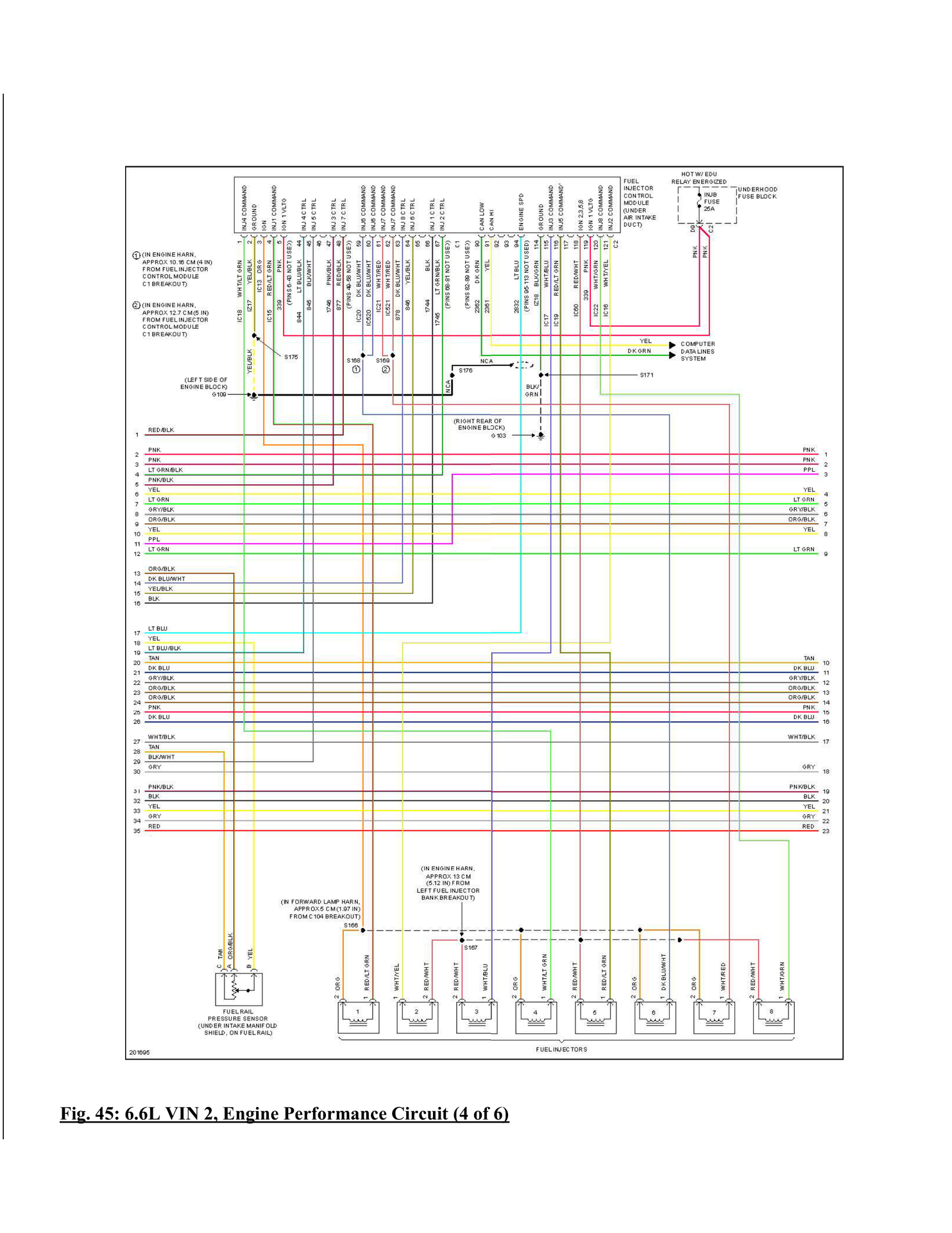
This article will delve deeper into the Lb7 Duramax Wiring Harness Diagram, exploring its components, functionalities, and significance in maintaining optimal engine performance.
The Lb7 Duramax Wiring Harness Diagram plays a pivotal role in the proper functioning and maintenance of the Lb7 Duramax engine. It serves as a roadmap for understanding the intricate electrical connections and components within the engine’s wiring system. To fully comprehend the significance of this diagram, let’s delve into its key aspects:
- Schematic Representation: A visual depiction of the wiring system, aiding in troubleshooting and repairs.
- Electrical Connections: Outlines the pathways for electrical signals and power distribution.
- Component Identification: Shows the location and function of various electrical components.
- Circuit Tracing: Enables technicians to follow electrical circuits for fault diagnosis.
- Maintenance and Repair: Guides proper maintenance procedures and facilitates repairs.
- Diagnostic Tool: Used in conjunction with diagnostic tools for efficient troubleshooting.
- Customization and Modifications: Serves as a reference for customizing or modifying the wiring system.
- Engine Performance: Proper wiring ensures optimal engine performance and efficiency.
- Safety: Understanding the wiring diagram promotes safe electrical practices.
These aspects underscore the importance of the Lb7 Duramax Wiring Harness Diagram in maintaining a well-functioning engine and ensuring reliable performance. It provides a comprehensive understanding of the electrical system, facilitating troubleshooting, repairs, and modifications. By utilizing this diagram effectively, technicians can diagnose and address electrical issues accurately, ensuring the longevity and optimal operation of the Lb7 Duramax engine.
Schematic Representation
Within the context of the Lb7 Duramax Wiring Harness Diagram, schematic representation plays a pivotal role in simplifying complex electrical systems for effective troubleshooting and repairs. This visual depiction provides a comprehensive overview of the wiring system, enabling technicians to navigate the intricate network of electrical connections and components.
- Circuit Visualization: The diagram offers a clear representation of electrical circuits, allowing technicians to trace signal paths, identify potential breaks or shorts, and pinpoint faulty components.
- Component Identification: Schematic diagrams include symbols and labels for various electrical components, such as sensors, actuators, and modules, making it easy to locate and identify specific parts within the system.
- Real-Life Examples: These diagrams are based on real-world wiring configurations, ensuring accuracy and practical relevance. Technicians can directly apply the information to diagnose and repair actual electrical issues.
- Troubleshooting Guide: Schematic representations serve as a valuable troubleshooting guide, providing insights into potential failure points and guiding technicians through the process of identifying and resolving electrical problems.
In summary, the schematic representation aspect of the Lb7 Duramax Wiring Harness Diagram empowers technicians with a comprehensive visual aid for troubleshooting and repairs. By providing a clear understanding of the electrical system, it enables efficient diagnosis, accurate identification of faulty components, and effective resolution of electrical issues, ensuring optimal engine performance and reliability.
Electrical Connections
Within the context of the Lb7 Duramax Wiring Harness Diagram, electrical connections play a fundamental role in defining the pathways for electrical signals and power distribution throughout the engine system. These connections establish a network of conductive paths, ensuring that electrical signals can travel reliably between various components and modules.
Each electrical connection is meticulously designed to meet specific functional requirements, such as providing power to sensors, actuators, and control units. The diagram serves as a comprehensive roadmap, detailing the precise layout and configuration of these connections, enabling technicians to trace the flow of electrical signals and power throughout the system.
Understanding electrical connections is critical for diagnosing and repairing electrical faults. By analyzing the wiring diagram, technicians can identify potential points of failure, such as loose connections, damaged wires, or faulty components. This information empowers them to pinpoint the root cause of electrical issues and implement effective repairs, restoring optimal engine performance and reliability.
In summary, the electrical connections outlined in the Lb7 Duramax Wiring Harness Diagram are essential for maintaining proper electrical functionality within the engine system. By providing a visual representation of these connections, the diagram empowers technicians with the knowledge and tools necessary to diagnose and resolve electrical issues efficiently, ensuring smooth engine operation and optimal performance.
Component Identification
Within the context of the Lb7 Duramax Wiring Harness Diagram, component identification plays a fundamental role in understanding and maintaining the intricate electrical network of the engine system. It provides a comprehensive overview of the location and function of various electrical components, enabling technicians to effectively diagnose and resolve electrical issues.
- Sensor Identification: The diagram precisely identifies and locates various sensors within the engine system, such as temperature sensors, pressure sensors, and position sensors. This knowledge is crucial for understanding how the engine monitors its operating parameters and responds accordingly.
- Actuator Identification: The diagram clearly outlines the location and function of actuators, such as solenoids, relays, and motor controllers. This information empowers technicians to trace the pathways through which the engine control module (ECM) commands and controls various engine functions.
- Module Identification: The diagram identifies and locates electronic control modules (ECMs), body control modules (BCMs), and other electronic modules within the engine system. This knowledge is essential for understanding how these modules communicate and coordinate various engine functions.
- Connector Identification: The diagram provides detailed information on the location and type of electrical connectors used throughout the wiring harness. This enables technicians to easily identify and disconnect connectors for maintenance, troubleshooting, or repairs.
In summary, the component identification aspect of the Lb7 Duramax Wiring Harness Diagram serves as a comprehensive guide to the electrical components within the engine system. By providing precise information on the location and function of these components, the diagram empowers technicians to efficiently diagnose and repair electrical issues, ensuring optimal engine performance and reliability.
Circuit Tracing
Within the context of the Lb7 Duramax Wiring Harness Diagram, circuit tracing plays a pivotal role in diagnosing and resolving electrical faults within the engine system. It involves following the pathway of electrical circuits to identify potential breaks, shorts, or malfunctioning components that may disrupt proper engine operation.
The Lb7 Duramax Wiring Harness Diagram serves as an essential tool for circuit tracing, providing a visual representation of the electrical connections and components within the engine system. By utilizing this diagram, technicians can systematically trace electrical circuits, guided by the schematic representation and component identification information. This enables them to pinpoint the exact location of faults, even in complex wiring systems, significantly reducing diagnostic time and effort.
In real-world applications, circuit tracing is indispensable for troubleshooting a wide range of electrical issues. For instance, if an engine sensor is malfunctioning, technicians can use the wiring diagram to trace the circuit associated with that sensor, checking for loose connections, damaged wires, or faulty components along the way. By isolating the fault to a specific section of the circuit, technicians can quickly identify and replace the defective component, restoring optimal engine performance.
Moreover, the understanding gained through circuit tracing extends beyond fault diagnosis. It empowers technicians with a comprehensive knowledge of the electrical system, enabling them to perform modifications or upgrades with confidence. By tracing circuits and understanding their functionality, technicians can make informed decisions regarding electrical system modifications, ensuring compatibility and proper operation.
In summary, circuit tracing is a critical component of the Lb7 Duramax Wiring Harness Diagram, providing technicians with the ability to diagnose and resolve electrical faults efficiently. Through the visual representation of electrical circuits and component identification, the wiring diagram empowers technicians to trace circuits, identify faults, and implement effective repairs, ensuring optimal engine performance and reliability.
Maintenance and Repair
Within the context of “Lb7 Duramax Wiring Harness Diagram,” the aspect of maintenance and repair plays a crucial role in ensuring the longevity and optimal performance of the engine system. The wiring harness diagram serves as a comprehensive guide for proper maintenance procedures and facilitates efficient repairs, empowering technicians to maintain the electrical integrity and functionality of the engine.
- Component Inspection and Testing: The diagram provides guidance on regular inspection and testing of electrical components, enabling technicians to identify potential issues before they lead to major failures. This includes checking for loose connections, damaged wires, and faulty sensors, ensuring the reliability of the electrical system.
- Maintenance Schedules: The diagram can be utilized to develop tailored maintenance schedules based on the specific operating conditions of the engine. By adhering to these schedules, technicians can proactively replace or repair components before they reach the end of their service life, preventing unexpected breakdowns and costly repairs.
- Troubleshooting and Diagnostics: When electrical issues arise, the wiring harness diagram serves as a valuable troubleshooting tool. Technicians can use it to trace circuits, identify faulty components, and determine the root cause of electrical malfunctions. This facilitates targeted repairs, minimizing downtime and maximizing engine efficiency.
- Modification and Upgrades: For enthusiasts or those seeking to enhance engine performance, the wiring harness diagram provides a roadmap for electrical modifications and upgrades. By understanding the electrical system layout, technicians can confidently make changes to accommodate performance enhancements, ensuring compatibility and proper integration with the existing wiring harness.
In summary, the “Maintenance and Repair: Guides proper maintenance procedures and facilitates repairs” aspect of the “Lb7 Duramax Wiring Harness Diagram” empowers technicians with the knowledge and tools to maintain, diagnose, and repair the engine’s electrical system effectively. By providing a comprehensive visual representation of the wiring harness, the diagram enables proactive maintenance, accurate troubleshooting, and efficient repairs, ensuring the optimal performance and longevity of the Lb7 Duramax engine.
Diagnostic Tool
Within the context of “Lb7 Duramax Wiring Harness Diagram,” the aspect of “Diagnostic Tool: Used in conjunction with diagnostic tools for efficient troubleshooting” plays a critical role in maintaining optimal engine performance and minimizing downtime. The wiring harness diagram serves as a valuable aid in conjunction with diagnostic tools, enabling technicians to pinpoint electrical faults accurately and efficiently.
- Diagnostic Codes: The wiring harness diagram provides insights into the diagnostic trouble codes (DTCs) generated by the engine’s electronic control module (ECM). By matching DTCs to specific circuits and components, technicians can quickly identify the root cause of electrical issues.
- Multimeter Usage: The diagram guides technicians in using a multimeter to measure voltage, resistance, and continuity within the electrical system. This enables them to verify the functionality of sensors, actuators, and wiring, identifying potential electrical faults.
- Scan Tool Compatibility: The wiring harness diagram ensures compatibility with various scan tools used for engine diagnostics. Technicians can connect scan tools to the vehicle’s data port and utilize the diagram to interpret sensor data, actuator commands, and other diagnostic information.
- Signal Tracing: The diagram aids in tracing electrical signals throughout the wiring harness, allowing technicians to identify signal interruptions or malfunctions. This facilitates the isolation of faulty components and ensures proper signal transmission within the electrical system.
In summary, the “Diagnostic Tool: Used in conjunction with diagnostic tools for efficient troubleshooting” aspect of the “Lb7 Duramax Wiring Harness Diagram” empowers technicians with the knowledge and tools to diagnose electrical faults accurately and efficiently. By utilizing the diagram in conjunction with diagnostic tools, technicians can minimize downtime, ensure optimal engine performance, and maintain the overall integrity of the electrical system.
Customization and Modifications
Within the context of the “Lb7 Duramax Wiring Harness Diagram,” the aspect of “Customization and Modifications: Serves as a reference for customizing or modifying the wiring system” holds significant importance, empowering individuals with the knowledge and guidance to tailor the electrical system to their specific requirements or preferences. This section will delve into various facets of customization and modifications, exploring their components, real-life examples, and implications within the broader scope of the “Lb7 Duramax Wiring Harness Diagram.
-
Performance Enhancements:
The wiring harness diagram provides insights into modifying the electrical system to accommodate performance upgrades, such as turbochargers, fuel injectors, and engine management systems. By understanding the electrical connections and components involved, enthusiasts can make informed decisions regarding upgrades, ensuring compatibility and optimal performance. -
Accessory Integrations:
The diagram serves as a reference for integrating additional accessories, such as lighting systems, audio components, and towing modules. It guides individuals in determining the appropriate electrical connections, power requirements, and potential impacts on the existing wiring system, ensuring seamless integration of aftermarket accessories. -
Diagnostics and Troubleshooting:
Customization and modifications may introduce unique challenges in diagnosing and troubleshooting electrical issues. The wiring harness diagram becomes even more crucial in these situations, enabling individuals to trace modified circuits, identify potential points of failure, and resolve electrical malfunctions efficiently. -
Compliance and Safety:
When customizing or modifying the wiring system, adhering to electrical standards and safety guidelines is paramount. The wiring harness diagram provides a framework for ensuring proper electrical practices, preventing potential hazards, and maintaining the integrity of the electrical system.
In summary, the “Customization and Modifications: Serves as a reference for customizing or modifying the wiring system” aspect of the “Lb7 Duramax Wiring Harness Diagram” empowers individuals with the knowledge and guidance to tailor the electrical system to their specific needs, enhance performance, integrate accessories, and ensure compliance and safety. By understanding the electrical connections, components, and potential implications of modifications, individuals can confidently make informed decisions, ensuring optimal functionality and performance of the electrical system within the context of the “Lb7 Duramax Wiring Harness Diagram.”
Engine Performance
Within the context of the “Lb7 Duramax Wiring Harness Diagram,” understanding the relationship between engine performance and proper wiring is crucial for maintaining optimal engine operation and efficiency. The wiring harness diagram provides a comprehensive blueprint of the electrical connections and components within the engine system. It serves as a vital tool for ensuring that all electrical components are properly connected and functioning as intended, directly impacting the overall performance of the engine.
Improper wiring can lead to a variety of issues, including engine misfires, reduced power output, increased fuel consumption, and difficulty starting. Faulty wiring can also cause damage to electrical components, leading to costly repairs and potential safety hazards. Therefore, having a thorough understanding of the wiring harness diagram is essential for diagnosing and resolving electrical problems, ensuring that the engine operates at its peak efficiency.
In real-world applications, the “Lb7 Duramax Wiring Harness Diagram” plays a critical role in maintaining optimal engine performance. For instance, proper wiring ensures that the fuel injectors receive the correct signals from the engine control module (ECM), resulting in precise fuel delivery and optimal combustion. Similarly, correct wiring of the ignition system ensures proper spark timing and ignition, leading to efficient engine operation and reduced emissions.
Understanding the connection between engine performance and proper wiring allows technicians and enthusiasts to make informed decisions regarding electrical modifications and upgrades. By utilizing the “Lb7 Duramax Wiring Harness Diagram,” they can confidently modify the wiring system to accommodate performance enhancements, such as turbocharger installations or fuel system upgrades, while ensuring that the electrical system remains stable and reliable.
In summary, the “Engine Performance: Proper wiring ensures optimal engine performance and efficiency.” aspect of the “Lb7 Duramax Wiring Harness Diagram” underscores the critical relationship between electrical integrity and engine performance. By understanding this connection, individuals can maintain, diagnose, and modify the electrical system effectively, ensuring that the engine operates at its optimal potential, delivering reliable power and efficiency.
Safety
The “Lb7 Duramax Wiring Harness Diagram” serves as a crucial guide for ensuring the safe and proper functioning of the electrical system within the engine. Understanding this diagram empowers individuals with the knowledge to identify and avoid potential electrical hazards, preventing accidents, damage to components, and ensuring the overall safety of the vehicle and its occupants.
- Hazard Identification and Prevention: The wiring diagram provides insights into potential electrical hazards, such as short circuits, overloads, and improper grounding. By understanding these hazards, individuals can take proactive measures to prevent them, such as using proper wiring techniques, selecting appropriate fuses and circuit breakers, and ensuring adequate insulation.
- Safe Electrical Modifications: When performing electrical modifications or upgrades, the wiring diagram serves as a reference for ensuring that changes are made safely and in accordance with electrical standards. It guides individuals in selecting compatible components, determining appropriate wire gauges, and routing wires safely, preventing potential electrical issues or fire hazards.
- Diagnostic and Troubleshooting Safety: In the event of electrical faults, the wiring diagram enables safe and effective troubleshooting. It helps individuals identify the affected circuits, locate potential , and perform testing procedures without risking further damage to the electrical system or creating electrical hazards.
- Electrical Fire Prevention: Electrical fires are a significant concern, and the wiring diagram plays a vital role in preventing them. By understanding the proper wiring techniques, component ratings, and circuit protection measures outlined in the diagram, individuals can minimize the risk of electrical fires and ensure the safety of the vehicle and its occupants.
In summary, the “Safety: Understanding the wiring diagram promotes safe electrical practices.” aspect of the “Lb7 Duramax Wiring Harness Diagram” underscores the importance of electrical safety in the context of engine operation. By providing a comprehensive visual representation of the electrical system, the diagram empowers individuals to make informed decisions regarding electrical modifications, identify potential hazards, and perform troubleshooting procedures safely. This knowledge contributes to the overall reliability, performance, and safety of the vehicle, ensuring peace of mind and preventing costly or dangerous electrical problems.


Related Posts


