A 2 Wire Hard Start Kit Wiring Diagram is a guide to connecting components in a hard start kit for a single-phase induction motor. The diagram specifies the connections between the capacitor, relay, and motor terminals allowing the motor to start under heavy loads. For instance, a 2 Wire Hard Start Kit Wiring Diagram for a 1.5 HP motor may indicate connecting the capacitor to the relay’s “C” and “S” terminals, the relay’s “R” and “L” terminals to the motor’s “R” and “L” terminals, and the relay’s “S” terminal to the motor’s “S” terminal.
These diagrams are crucial as they ensure the correct installation of hard start kits, which provide extra torque during motor startup. This prevents motor burnout and extends its lifespan. The development of 2 Wire Hard Start Kit Wiring Diagrams in the 1960s simplified the installation process, making it accessible to a wider range of technicians.
This article will delve into the details of 2 Wire Hard Start Kit Wiring Diagrams, covering their components, wiring procedures, safety precautions, and troubleshooting techniques to help you understand and implement them effectively.
The key aspects of a 2 Wire Hard Start Kit Wiring Diagram are crucial for understanding how to correctly install and use a hard start kit for a single-phase induction motor. These aspects cover the various components, wiring procedures, safety precautions, and troubleshooting techniques involved in the process.
- Components: Capacitor, relay, motor terminals
- Wiring: Connections between components
- Procedures: Step-by-step instructions for installation
- Safety: Precautions to prevent electrical hazards
- Troubleshooting: Identifying and resolving common issues
- Motor compatibility: Matching the kit to the motor’s specifications
- Capacitor sizing: Determining the appropriate capacitance value
- Relay selection: Choosing the correct relay for the application
- Wiring diagram interpretation: Understanding the symbols and connections
- Code compliance: Adhering to electrical codes and standards
By understanding these key aspects, technicians can ensure the proper installation and operation of 2 Wire Hard Start Kits, preventing motor burnout, extending its lifespan, and ensuring optimal performance. These diagrams serve as a valuable guide for both experienced electricians and DIY enthusiasts, enabling them to tackle motor starting challenges effectively and safely.
Components
In the context of a 2 Wire Hard Start Kit Wiring Diagram, the capacitor, relay, and motor terminals are essential components that work together to provide extra torque during the starting phase of a single-phase induction motor. The capacitor stores electrical energy and releases it at the appropriate time to create a rotating magnetic field in the motor, assisting it in overcoming the initial resistance and starting smoothly.
The relay is responsible for connecting and disconnecting the capacitor from the circuit. When the motor is turned on, the relay energizes and closes the circuit, allowing the capacitor to discharge its stored energy into the motor windings. Once the motor reaches a certain speed, the relay opens the circuit, disconnecting the capacitor and allowing the motor to operate normally.
The motor terminals are the points of connection between the motor and the wiring diagram. The capacitor and relay are connected to the motor terminals in a specific configuration, as indicated in the wiring diagram. This configuration ensures that the capacitor is properly charged and discharged, and that the relay operates correctly to provide the necessary starting assistance to the motor.
Understanding the relationship between these components is crucial for correctly installing and using a 2 Wire Hard Start Kit. By following the wiring diagram and ensuring that the components are connected properly, technicians can prevent motor burnout, extend its lifespan, and ensure optimal performance. These diagrams serve as a valuable guide for both experienced electricians and DIY enthusiasts, enabling them to tackle motor starting challenges effectively and safely.
Wiring
In the context of a 2 Wire Hard Start Kit Wiring Diagram, the wiring connections between components play a critical role in ensuring the proper functioning of the hard start kit and the motor it is connected to. These connections allow the capacitor to discharge its stored energy into the motor windings at the appropriate time, providing the extra torque needed to overcome the initial resistance and start the motor smoothly.
Without proper wiring connections, the capacitor would not be able to discharge its energy effectively, and the motor would struggle to start or might not start at all. The wiring diagram provides a clear and concise guide on how to connect the capacitor, relay, and motor terminals correctly, ensuring that the circuit is complete and the components can operate as intended.
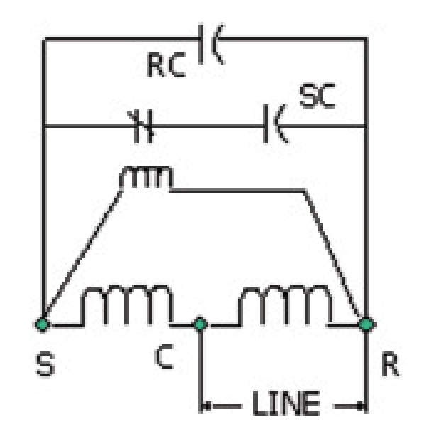
Real-life examples of wiring connections within a 2 Wire Hard Start Kit Wiring Diagram include the connection between the capacitor’s positive terminal to the relay’s “C” terminal, the capacitor’s negative terminal to the relay’s “S” terminal, the relay’s “R” terminal to the motor’s “R” terminal, and the relay’s “L” terminal to the motor’s “L” terminal. These connections are essential for the proper functioning of the hard start kit and must be made according to the diagram to ensure optimal performance and safety.
Understanding the wiring connections between components is crucial for technicians and DIY enthusiasts who work with 2 Wire Hard Start Kits. By following the wiring diagram carefully and ensuring that the connections are made correctly, they can prevent potential hazards such as electrical shorts, motor burnout, and even fire. Proper wiring also ensures that the motor receives the necessary starting assistance, extending its lifespan and preventing costly repairs or replacements.
Procedures
In the context of a 2 Wire Hard Start Kit Wiring Diagram, procedures that provide step-by-step instructions for installation are critical for ensuring the proper functioning and safety of the hard start kit and the motor it is connected to. These procedures guide the user through the process of connecting the capacitor, relay, and motor terminals in the correct sequence and configuration, as specified in the wiring diagram.
Without clear and accurate step-by-step installation procedures, there is a high risk of incorrect wiring, which can lead to potential hazards such as electrical shorts, motor burnout, or even fire. The procedures ensure that the hard start kit is installed correctly, providing the necessary starting assistance to the motor while maintaining safety standards.
Real-life examples of step-by-step installation procedures within a 2 Wire Hard Start Kit Wiring Diagram include:
- Mounting the capacitor and relay in a suitable location near the motor.
- Connecting the capacitor’s positive terminal to the relay’s “C” terminal.
- Connecting the capacitor’s negative terminal to the relay’s “S” terminal.
- Connecting the relay’s “R” terminal to the motor’s “R” terminal.
- Connecting the relay’s “L” terminal to the motor’s “L” terminal.
- Double-checking all connections to ensure they are secure and correct.
Understanding the importance of step-by-step installation procedures and following them carefully is crucial for technicians and DIY enthusiasts who work with 2 Wire Hard Start Kits. By adhering to the specified procedures, they can ensure the proper functioning of the hard start kit, prevent potential hazards, and extend the lifespan of the motor.
Safety
When working with electrical components and wiring diagrams, adhering to safety precautions is paramount to prevent electrical hazards and ensure the safe and proper functioning of the system. In the context of 2 Wire Hard Start Kit Wiring Diagrams, these precautions are critical for protecting both the equipment and the individuals involved in the installation and operation process.
- Proper Insulation: All electrical wires and connections must be properly insulated to prevent electrical shocks and short circuits. This includes using appropriate wire gauges, insulation materials, and ensuring that all connections are secure and protected from moisture and other environmental factors.
- Grounding: Grounding provides a safe path for electrical current to flow in the event of a fault or surge, preventing damage to equipment and protecting individuals from electrical shocks. Proper grounding must be implemented in accordance with electrical codes and standards.
- Overcurrent Protection: Overcurrent protection devices, such as fuses or circuit breakers, are essential to prevent electrical fires and damage to equipment. These devices trip or blow when the electrical current exceeds a safe level, interrupting the circuit and preventing further damage.
- Lockout/Tagout Procedures: Lockout/tagout procedures are used to ensure that electrical equipment is de-energized and isolated before performing any maintenance or repairs. This prevents accidental energization of the equipment, protecting workers from electrical hazards.
By understanding and adhering to these safety precautions, technicians and individuals working with 2 Wire Hard Start Kit Wiring Diagrams can minimize the risk of electrical hazards, ensuring a safe and reliable electrical system.
Troubleshooting
Troubleshooting is an essential aspect of working with 2 Wire Hard Start Kit Wiring Diagrams, enabling technicians and individuals to identify and resolve common issues that may arise during the installation or operation of the hard start kit. By understanding potential problems and their solutions, it becomes easier to ensure the proper functioning and longevity of the motor and its associated components.
- Identifying Faulty Components: Troubleshooting involves identifying faulty components within the hard start kit, such as a malfunctioning capacitor or relay. This can be done through visual inspection, continuity testing, or using specialized diagnostic tools.
- Incorrect Wiring: Checking for incorrect wiring is crucial, as any deviations from the wiring diagram can lead to improper functioning or even damage to the motor. This includes verifying that all connections are secure, properly insulated, and .
- Motor Overload: Troubleshooting also involves identifying signs of motor overload, such as overheating, excessive noise, or unusual vibrations. This can be caused by factors such as prolonged operation under heavy loads or insufficient ventilation, and it requires addressing the underlying cause to prevent motor damage.
- Electrical Hazards: Troubleshooting encompasses identifying and resolving potential electrical hazards, such as loose connections, exposed wires, or improper grounding. These hazards can pose safety risks and should be addressed promptly to prevent accidents or electrical fires.
By understanding and addressing these common issues, technicians and individuals can effectively troubleshoot 2 Wire Hard Start Kit Wiring Diagrams, ensuring the safe and reliable operation of the motor. Troubleshooting empowers them to identify problems early on, implement appropriate solutions, and prevent costly repairs or replacements in the long run.
Motor compatibility
In the context of 2 Wire Hard Start Kit Wiring Diagrams, motor compatibility plays a critical role in ensuring the proper functioning and longevity of the motor. A correctly matched hard start kit provides the optimal starting assistance for the specific motor it is connected to, preventing excessive strain or damage to the motor.
When selecting a 2 Wire Hard Start Kit, it is essential to consider the motor’s specifications, including its horsepower, voltage, and starting current. The wiring diagram should be compatible with the motor’s electrical characteristics to provide the appropriate level of starting assistance. Using a hard start kit that is not matched to the motor’s specifications can lead to insufficient starting torque, overheating, or even motor burnout.
Real-life examples of motor compatibility within 2 Wire Hard Start Kit Wiring Diagrams include matching a 1000F capacitor and a 120V relay to a 1.5 HP, 120V motor. This combination provides the necessary starting torque to overcome the initial resistance of the motor and ensure smooth startup.
Understanding the importance of motor compatibility empowers technicians and individuals to select and install the correct 2 Wire Hard Start Kit, ensuring optimal motor performance and extending its lifespan. By adhering to the wiring diagram and carefully matching the kit to the motor’s specifications, they can prevent costly repairs or replacements and maintain a reliable electrical system.
Capacitor sizing
In the context of 2 Wire Hard Start Kit Wiring Diagrams, capacitor sizing is a critical aspect that directly impacts the effectiveness and safety of the motor starting process. An appropriately sized capacitor provides the optimal amount of starting torque to overcome the initial resistance of the motor, ensuring a smooth and efficient startup. Conversely, an incorrectly sized capacitor can result in insufficient starting torque or excessive strain on the motor, leading to potential damage or reduced lifespan.
- Motor Specifications: The starting current and voltage of the motor are key factors in determining the appropriate capacitor size. Matching the capacitor’s capacitance to the motor’s characteristics ensures that the capacitor provides the necessary starting torque without overloading the motor.
- Capacitor Voltage Rating: The capacitor’s voltage rating must exceed the motor’s operating voltage to prevent premature failure or safety hazards. Choosing a capacitor with an appropriate voltage rating ensures reliable operation under normal operating conditions.
- Capacitance Value: The capacitance value of the capacitor determines the amount of charge it can store. Selecting the correct capacitance value is crucial to provide the optimal starting torque while preventing excessive voltage drop or overheating.
- Temperature Considerations: Capacitors are sensitive to temperature variations. Choosing a capacitor with a temperature rating that matches the motor’s operating environment ensures stable performance and extended lifespan.
Understanding and adhering to the principles of capacitor sizing is essential for technicians and individuals working with 2 Wire Hard Start Kit Wiring Diagrams. By carefully considering the motor specifications and selecting the appropriate capacitor size, they can ensure the safe and efficient operation of the motor, preventing costly repairs or replacements and extending its service life.
Relay selection
In the context of 2 Wire Hard Start Kit Wiring Diagrams, relay selection plays a critical role in ensuring the proper functionality and safety of the motor starting process. The relay serves as the intermediary between the capacitor and the motor, controlling the flow of current to provide the necessary starting torque.
When selecting a relay for a 2 Wire Hard Start Kit, several factors must be considered, including the motor’s specifications, the capacitor’s capacitance, and the operating environment. A correctly chosen relay ensures that the capacitor is charged and discharged at the appropriate time, providing the optimal starting assistance while preventing damage to the motor or the relay itself.
Real-life examples of relay selection within 2 Wire Hard Start Kit Wiring Diagrams include using a relay with a coil voltage matching the motor’s operating voltage, a contact rating that exceeds the capacitor’s discharge current, and a temperature rating suitable for the motor’s operating environment. Understanding the importance of relay selection empowers technicians and individuals to make informed choices, ensuring the safe and efficient operation of the motor.
In summary, relay selection is a critical component of 2 Wire Hard Start Kit Wiring Diagrams. By understanding the principles of relay selection and matching the relay to the specific motor and application requirements, technicians and individuals can prevent costly repairs or replacements, extend the lifespan of the motor, and ensure a reliable electrical system.
Wiring diagram interpretation
Within the context of a “2 Wire Hard Start Kit Wiring Diagram”, interpreting the symbols and connections is paramount for successful installation and operation. This aspect involves understanding the graphical representation of components, their interconnections, and the flow of current within the circuit. Accurate interpretation of wiring diagrams ensures that the hard start kit is correctly integrated with the motor, providing optimal starting assistance while adhering to safety standards.
- Symbol Identification: Recognizing the symbols used to represent different components, such as capacitors, relays, motors, and terminals, is essential for proper wiring. These symbols are standardized and follow industry conventions, enabling technicians to quickly identify and understand the circuit layout.
- Connection Types: Wiring diagrams illustrate the types of connections between components, including series, parallel, and combinations thereof. Understanding these connection types is crucial for ensuring the correct flow of current and preventing short circuits or other electrical hazards.
- Polarity and Orientation: Some components, such as capacitors and diodes, have specific polarity or orientation requirements. Wiring diagrams clearly indicate the correct polarity and orientation to ensure proper functionality and prevent damage to the components.
- Circuit Analysis: Interpreting wiring diagrams involves analyzing the circuit as a whole, tracing the flow of current from the power source through the components and back to the power source. This analysis helps identify potential issues, such as loops or open circuits, before the circuit is energized.
By understanding and correctly interpreting the symbols and connections in a “2 Wire Hard Start Kit Wiring Diagram”, technicians and individuals can ensure the safe and effective operation of the motor. Accurate wiring eliminates potential hazards, extends the lifespan of the equipment, and ensures optimal performance under various load conditions.
Code compliance
Code compliance, which involves adhering to established electrical codes and standards, is an indispensable aspect of “2 Wire Hard Start Kit Wiring Diagram” as it ensures the safety and reliability of the electrical installation. By following these guidelines, technicians and individuals can minimize electrical hazards, prevent accidents, and guarantee that the hard start kit operates in accordance with regulatory requirements.
- Electrical Safety: Compliance with electrical codes ensures that the wiring diagram adheres to safety regulations, such as proper insulation, grounding, and overcurrent protection, mitigating the risk of electrical shocks, fires, and other hazards.
- Product Standards: Adhering to product standards, as specified by organizations like Underwriters Laboratories (UL) and the National Electrical Manufacturers Association (NEMA), guarantees that the components used in the wiring diagram meet industry-recognized safety and performance criteria.
- Local Regulations: Local building codes often have specific requirements for electrical installations, including hard start kits. Compliance with these regulations ensures that the installation meets the safety standards and inspection criteria set by local authorities.
- Insurance Coverage: Maintaining code compliance can impact insurance coverage in the event of an electrical incident. Insurance companies may require proof of compliance with electrical codes and standards to provide coverage, protecting property and individuals from financial liability.
Code compliance in “2 Wire Hard Start Kit Wiring Diagram” extends beyond mere adherence to regulations; it represents a commitment to safety, quality, and reliability. By incorporating code compliance into their practices, technicians and individuals contribute to a safer and more efficient electrical environment.


Related Posts


