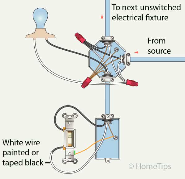
A “Light Switch Wiring Diagram 1 Way” illustrates the electrical connections required to control a single light fixture using a single switch. In homes, this setup is commonly used for individual room lighting.
Understanding and following these wiring diagrams ensures safe and proper electrical installations. They simplify complex electrical concepts, enabling basic maintenance and troubleshooting. Historically, the development of standardized wiring diagrams has greatly improved electrical safety and efficiency.
This article will explore the components, wiring procedures, and safety precautions associated with 1-way light switch wiring diagrams. It will provide a comprehensive guide for installing and maintaining basic electrical systems.
A light switch wiring diagram 1 way is a crucial part of electrical wiring, providing a safe and efficient way to control lighting in a room. Understanding the key aspects of these diagrams is essential for proper installation and maintenance.
- Circuit Design: Outlines the electrical path for the switch and light fixture.
- Wire Selection: Specifies the appropriate wire gauge and type for the circuit.
- Switch Type: Identifies the type of switch used, such as single-pole or double-pole.
- Connection Points: Indicates where the wires connect to the switch and fixture.
- Grounding: Ensures a safe electrical system by providing a path for excess electricity.
- Safety Precautions: Highlights potential hazards and safety measures to follow.
- Code Compliance: Adherence to electrical codes ensures compliance with safety standards.
- Troubleshooting: Provides guidance on identifying and resolving common electrical issues.
These aspects are interconnected and crucial for the proper functioning and safety of a 1-way light switch wiring diagram. Understanding these aspects empowers individuals to make informed decisions, perform basic electrical tasks, and maintain a safe electrical environment.
Circuit Design
In a light switch wiring diagram 1 way, circuit design holds paramount importance as it orchestrates the electrical flow from the power source, through the switch, and onwards to the light fixture. It ensures efficient and safe operation of the lighting system.
-
Power Source
The electrical journey commences at the power source, typically a circuit breaker panel, which provides the initial surge of electricity.
-
Switch
The switch acts as a gatekeeper, controlling the flow of electricity to the light fixture. When flipped, it either completes or interrupts the circuit.
-
Electrical Cable
The electrical cable serves as the conduit for electricity, carrying it from the switch to the light fixture. Proper gauge and insulation are crucial for safe operation.
-
Light Fixture
The light fixture, housing the bulb, is the ultimate destination of electricity, where illumination is produced.
Understanding circuit design allows for informed decision-making during installation and troubleshooting. It ensures adherence to electrical codes, safety protocols, and optimal performance of the lighting system.
Wire Selection
In the context of light switch wiring diagrams, wire selection plays a crucial role in ensuring the safe and efficient operation of the lighting system. It involves choosing the appropriate wire gauge, which refers to the thickness of the wire, and the type of insulation, which protects the wire from electrical hazards.
-
Current Capacity
The wire gauge must be able to handle the amount of current that will flow through the circuit. Using a wire with too small a gauge can lead to overheating and potential fire hazards.
-
Voltage Rating
The wire’s insulation must be rated for the voltage of the circuit. Using insulation that is not rated for the voltage can lead to electrical shock or fire hazards.
-
Environmental Conditions
The type of insulation used must be appropriate for the environmental conditions in which the wire will be installed. For example, if the wire will be installed in a wet location, it must have moisture-resistant insulation.
-
Code Compliance
The wire gauge and type must comply with the electrical codes in your area. Using wire that does not meet code can lead to failed inspections and potential safety hazards.
Understanding and adhering to the appropriate wire selection criteria are essential for the safe and effective installation of a light switch wiring diagram 1 way. By choosing the correct wire gauge and type, you can ensure that your lighting system operates as intended and meets all safety standards.
Switch Type
In the context of “Light Switch Wiring Diagram 1 Way”, understanding the switch type is crucial as it determines the electrical flow and functionality of the lighting system. Two primary switch types are commonly used: single-pole and double-pole switches.
-
Single-Pole Switch
A single-pole switch controls a single light fixture or a group of fixtures that are always turned on or off together. It has two terminals, one for the incoming power and one for the outgoing power to the light.
-
Double-Pole Switch
A double-pole switch is used to control two separate light fixtures or two circuits simultaneously. It has four terminals, two for the incoming power and two for the outgoing power to the lights.
Selecting the appropriate switch type is essential for the proper operation and safety of the lighting system. Single-pole switches are commonly used in residential applications, while double-pole switches are often employed in commercial or industrial settings where independent control of multiple circuits is required. Understanding the difference between these switch types empowers individuals to make informed decisions during installation and maintenance, ensuring a safe and efficient electrical system.
Connection Points
Within the realm of “Light Switch Wiring Diagram 1 Way”, “Connection Points: Indicates where the wires connect to the switch and fixture” holds utmost importance, as it outlines the precise locations where electrical wires are joined to establish a functional lighting system. Understanding these connection points is not only crucial for proper installation but also for troubleshooting and ensuring the safety and efficiency of the electrical circuit.
-
Switch Terminals
Switch terminals are the designated points on the switch where wires are secured to complete the electrical circuit. These terminals are typically labeled with screws or markings indicating the appropriate wire connections.
-
Fixture Terminals
Similar to switch terminals, fixture terminals are the connection points located on the light fixture where wires are attached to power the light source. Proper identification and connection of wires to these terminals ensure the illumination of the fixture.
-
Wire Nuts
Wire nuts, also known as wire connectors, are essential components used to join and insulate the ends of electrical wires at connection points. They provide a secure and reliable method of establishing electrical continuity while preventing short circuits.
-
Grounding Point
The grounding point is a crucial connection point that establishes a path for excess electricity to flow safely into the ground. This safety feature helps prevent electrical shocks and protects against electrical hazards.
Understanding and adhering to the proper connection points outlined in a “Light Switch Wiring Diagram 1 Way” is paramount for the safe and effective operation of the lighting system. Incorrect connections can lead to electrical malfunctions, safety hazards, and potential damage to the electrical components. By meticulously following the designated connection points, individuals can ensure the reliable and efficient performance of their lighting system, fostering a safe and well-illuminated environment.
Grounding
In the context of “Light Switch Wiring Diagram 1 Way,” the aspect of “Grounding: Ensures a safe electrical system by providing a path for excess electricity” plays a critical role in safeguarding against electrical hazards and ensuring the safe operation of the lighting system.
-
Electrical Safety
Grounding provides a dedicated path for excess electricity to flow safely into the ground, preventing it from accumulating in the system and potentially causing electrical shocks or fires.
-
Fault Protection
In the event of electrical faults, such as short circuits, grounding provides a low-resistance path for the fault current to travel, thereby protecting electrical equipment and preventing damage.
-
Electrical Code Compliance
Grounding is a fundamental requirement of electrical codes and standards, ensuring compliance with safety regulations and industry best practices.
-
Grounding Components
Proper grounding involves installing a grounding electrode, such as a ground rod or grounding plate, and connecting it to the electrical system. This grounding electrode provides the necessary connection to the earth.
Understanding and implementing effective grounding practices in “Light Switch Wiring Diagram 1 Way” is essential for fostering a safe and reliable electrical environment. By adhering to electrical codes, utilizing appropriate grounding components, and ensuring proper installation, individuals can mitigate electrical hazards, protect against faults, and promote the safe and efficient operation of their lighting systems.
Safety Precautions
Within the realm of “Light Switch Wiring Diagram 1 Way,” safety precautions hold paramount importance, guiding individuals towards the safe installation, operation, and maintenance of their lighting systems. Understanding and adhering to these precautions can prevent electrical hazards, injuries, and potential damage to property.
-
Electrical Shock Prevention
Electrical shock is a significant hazard associated with electrical work. Safety precautions emphasize the importance of de-energizing circuits before performing any electrical tasks, using insulated tools, and wearing appropriate personal protective equipment (PPE) to minimize the risk of shock.
-
Fire Prevention
Electrical fires can occur due to faulty wiring or overloaded circuits. Safety precautions highlight the need for using proper wire gauges and circuit protection devices, avoiding overloading circuits, and ensuring proper ventilation around electrical components to prevent overheating and potential fire hazards.
-
Grounding
Grounding is a crucial safety measure that provides a path for excess electricity to flow safely into the ground. Safety precautions emphasize the importance of proper grounding techniques, including using grounding rods or plates and connecting them to the electrical system, to protect against electrical faults and shock hazards.
-
Maintenance and Inspection
Regular maintenance and inspection of electrical systems are essential for ensuring ongoing safety. Safety precautions highlight the need for periodic inspections of wiring, switches, and fixtures to identify any potential hazards or deterioration. Prompt attention to any issues can prevent electrical problems and maintain a safe electrical environment.
By understanding and implementing the safety precautions outlined in “Light Switch Wiring Diagram 1 Way,” individuals can create and maintain safe and reliable lighting systems. These precautions serve as a vital guide for homeowners, DIY enthusiasts, and electrical professionals alike, fostering a safe and hazard-free electrical environment.
Code Compliance
In the context of “Light Switch Wiring Diagram 1 Way,” code compliance serves as a critical foundation for ensuring the safety and reliability of electrical installations. Electrical codes are established sets of rules and regulations developed by regulatory bodies to safeguard individuals and property from electrical hazards.
By adhering to code compliance, “Light Switch Wiring Diagram 1 Way” ensures that electrical installations meet these established safety standards. This includes proper wire sizing, circuit protection, grounding techniques, and installation practices. By following these codes, individuals can minimize the risk of electrical fires, shocks, and other hazards.
For instance, code compliance mandates the use of appropriate wire gauges to handle the electrical current safely. Undersized wires can overheat and pose a fire hazard, while oversized wires can be inefficient and wasteful. Similarly, proper grounding practices, as outlined in electrical codes, provide a safe path for excess electricity to flow into the ground, reducing the risk of electrical shocks and equipment damage.
Understanding and implementing code compliance in “Light Switch Wiring Diagram 1 Way” empowers individuals to create safe and reliable lighting systems. By adhering to these codes, homeowners, DIY enthusiasts, and electrical professionals can contribute to a safer electrical environment for themselves and others.
Troubleshooting
In the context of “Light Switch Wiring Diagram 1 Way,” troubleshooting plays a crucial role in maintaining a safe and functional lighting system. It empowers individuals to identify and resolve common electrical issues, ensuring the reliable operation of their lighting systems.
-
Identifying Potential Faults
Troubleshooting begins with identifying potential faults in the electrical circuit. This involves examining wires, switches, and fixtures for any visible damage or loose connections.
-
Testing Electrical Components
Using a multimeter or other testing equipment, individuals can check the continuity of wires and test the functionality of switches and fixtures. This helps isolate faulty components.
-
Resolving Common Issues
Once faulty components are identified, troubleshooting involves resolving common issues such as loose connections, faulty switches, or tripped circuit breakers. Repairing these issues typically involves tightening connections, replacing defective components, or resetting circuit breakers.
-
Understanding Electrical Codes
Troubleshooting electrical issues may require an understanding of basic electrical codes. Adhering to these codes ensures safety and compliance with regulatory standards.
By understanding and implementing troubleshooting techniques outlined in “Light Switch Wiring Diagram 1 Way,” individuals can effectively identify and resolve common electrical issues, maintaining the safety and functionality of their lighting systems. This empowers them to address minor electrical problems, reducing the need for professional assistance and promoting a safe and well-lit environment.


Related Posts


