A “1 4 Stereo Jack Wiring Diagram” refers to the specific arrangement of wires used to connect a 1/4-inch TRS (Tip-Ring-Sleeve) stereo jack to an audio device, enabling the transmission of both left and right stereo signals.
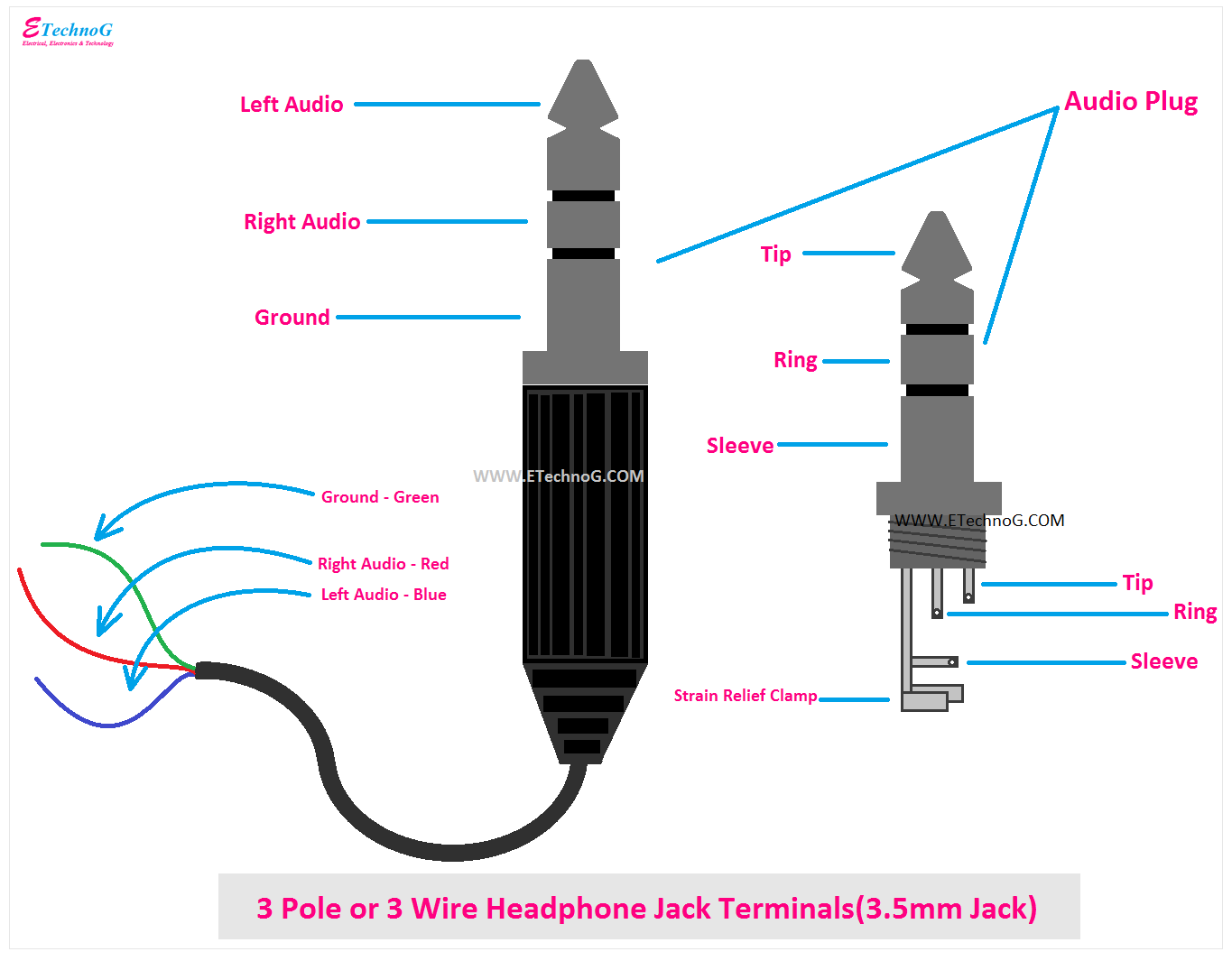
This wiring scheme is vital for establishing proper audio connections, as it defines the roles of each wire within the jack. The tip and sleeve are typically used for the left and right channels, respectively, while the ring is reserved for ground.
1/4-inch TRS stereo jacks are commonly found in audio devices ranging from guitars and keyboards to amplifiers and mixers. By adhering to the correct wiring diagram, audio engineers can ensure optimal signal transfer and prevent potential noise or interference.
Understanding the Part of Speech of the keyword “1 4 Stereo Jack Wiring Diagram” is essential to grasp its role in the topic. Identifying it as a noun implies that the content should primarily focus on the various aspects and attributes related to this type of wiring diagram.
- Connector Type: TRS (Tip-Ring-Sleeve) connector, commonly used in audio applications.
- Signal Transmission: Transmits both left and right stereo signals through a single cable.
- Wiring Configuration: Specific arrangement of wires within the jack for optimal signal transfer.
- Applications: Widely used in audio devices like guitars, keyboards, amplifiers, and mixers.
- Benefits: Ensures proper audio connections, reduces noise, and optimizes signal quality.
- Compatibility: Compatible with devices equipped with 1/4-inch TRS stereo jacks.
- Durability: Robust construction designed to withstand regular use and wear.
- Industry Standard: Widely adopted in the audio industry, ensuring compatibility across various devices.
- Cost-Effectiveness: Reasonably priced, making it accessible for both professional and home audio setups.
- Documentation: Easily accessible wiring diagrams and resources available online.
These key aspects collectively contribute to the significance and widespread adoption of the “1 4 Stereo Jack Wiring Diagram” in the audio industry. Understanding these aspects enables audio professionals and enthusiasts to make informed decisions, troubleshoot issues, and achieve optimal audio performance.
Connector Type: TRS (Tip-Ring-Sleeve) connector, commonly used in audio applications.
TRS (Tip-Ring-Sleeve) connectors are at the heart of “1 4 Stereo Jack Wiring Diagram”, defining the physical connection and signal transmission method. Understanding their components and applications is crucial for proper audio signal management.
-
Parts and Construction
TRS connectors consist of three conductive elements: the tip, ring, and sleeve. These elements are insulated and housed within a metal barrel, ensuring durability and efficient signal transfer. -
Signal Transmission
TRS connectors enable the transmission of both left and right stereo signals through a single cable. The tip carries the left channel signal, the ring carries the right channel signal, and the sleeve serves as the common ground reference. -
Compatibility
TRS connectors are designed to work with devices equipped with matching TRS jacks. This compatibility ensures a secure connection and optimal signal transfer across various audio components, including guitars, keyboards, amplifiers, and mixers. -
Durability
TRS connectors are built to withstand the rigors of frequent use and movement. Their robust construction ensures reliable connections and minimizes the risk of signal loss or interference.
In summary, TRS connectors play a vital role in “1 4 Stereo Jack Wiring Diagram” by providing a standardized and reliable method for connecting audio devices. Their ability to transmit stereo signals, durability, and compatibility make them the preferred choice for a wide range of audio applications.
Signal Transmission: Transmits both left and right stereo signals through a single cable.
The ability to transmit both left and right stereo signals through a single cable is a defining aspect of “1 4 Stereo Jack Wiring Diagram”. This feature enables efficient and convenient audio signal management in various applications.
-
Balanced Transmission
TRS connectors employed in “1 4 Stereo Jack Wiring Diagram” support balanced transmission. This method cancels out electromagnetic interference (EMI) and radio frequency interference (RFI), resulting in a cleaner and more reliable audio signal. -
Reduced Cable Clutter
The single-cable design of “1 4 Stereo Jack Wiring Diagram” reduces cable clutter and simplifies setup, particularly in complex audio systems. This is especially beneficial in live sound applications, where multiple instruments and devices are interconnected. -
Cost-Effectiveness
Using a single cable is more cost-effective than running separate cables for left and right channels. This cost reduction can be significant in large-scale installations or when dealing with multiple audio sources. -
Compatibility
“1 4 Stereo Jack Wiring Diagram” is compatible with a wide range of audio devices equipped with TRS jacks. This compatibility ensures seamless integration and signal transmission across various components, making it a versatile solution for professional and home audio setups.
In summary, the signal transmission capabilities of “1 4 Stereo Jack Wiring Diagram” provide numerous advantages, including noise reduction, simplified setup, cost-effectiveness, and compatibility. These benefits make it an essential aspect of modern audio signal management and a cornerstone of various audio applications.
Wiring Configuration: Specific arrangement of wires within the jack for optimal signal transfer.
Within the realm of “1 4 Stereo Jack Wiring Diagram”, the wiring configuration plays a crucial role in ensuring optimal signal transfer. The specific arrangement of wires within the jack is meticulously designed to maintain signal integrity and minimize interference.
The TRS (Tip-Ring-Sleeve) connector employed in “1 4 Stereo Jack Wiring Diagram” relies on a specific wiring configuration to transmit both left and right stereo signals. The tip carries the left channel signal, the ring carries the right channel signal, and the sleeve serves as the common ground reference. This configuration ensures balanced transmission, which effectively cancels out noise and interference.
Real-life examples of “Wiring Configuration” within “1 4 Stereo Jack Wiring Diagram” can be found in various audio devices. Guitars, keyboards, amplifiers, and mixers commonly utilize TRS jacks and rely on the proper wiring configuration to deliver clear and accurate audio signals.
Understanding the wiring configuration is essential for troubleshooting and maintaining audio systems. Incorrect wiring can lead to signal loss, noise, or even damage to equipment. By adhering to the established wiring standards, audio professionals and enthusiasts can ensure reliable and high-quality audio performance.
In summary, the wiring configuration within “1 4 Stereo Jack Wiring Diagram” is a critical component that enables optimal signal transfer. Its importance lies in maintaining signal integrity, minimizing interference, and ensuring compatibility across different audio devices. Understanding this wiring configuration is crucial for effective audio system design, troubleshooting, and maintenance.
Applications: Widely used in audio devices like guitars, keyboards, amplifiers, and mixers.
The extensive use of “1 4 Stereo Jack Wiring Diagram” in audio devices such as guitars, keyboards, amplifiers, and mixers stems from its ability to efficiently transmit high-quality stereo signals. This wiring scheme is a fundamental component of these devices, enabling them to interconnect and communicate effectively within audio systems.
In electric guitars, “1 4 Stereo Jack Wiring Diagram” is employed to transmit the instrument’s signal to an amplifier. The TRS connector allows for both mono and stereo output options, catering to different amplifier configurations and effects setups.
Keyboards and synthesizers utilize “1 4 Stereo Jack Wiring Diagram” for both audio output and MIDI data transmission. The balanced signal transmission provided by TRS connectors ensures noise-free signal transfer over extended cable lengths, maintaining the integrity of the audio and data signals.
Amplifiers rely on “1 4 Stereo Jack Wiring Diagram” for connecting guitars, keyboards, and other audio sources. The TRS connectors facilitate balanced signal transmission, preserving the signal quality and minimizing noise and interference.
Mixers employ “1 4 Stereo Jack Wiring Diagram” extensively for signal routing and mixing. These devices use TRS connectors to accept inputs from various audio sources and combine them into a cohesive stereo mix. The wiring scheme allows for flexible signal routing, panning, and level control.
Understanding the connection between ” Applications: Widely used in audio devices like guitars, keyboards, amplifiers, and mixers.” and “1 4 Stereo Jack Wiring Diagram” is crucial for audio professionals and enthusiasts. It enables them to properly connect and configure their equipment, ensuring optimal signal transfer and achieving the desired audio results.
In summary, “1 4 Stereo Jack Wiring Diagram” is a vital component in the operation of various audio devices. Its widespread use in guitars, keyboards, amplifiers, and mixers underscores its importance in establishing reliable and high-quality audio connections. Understanding the applications of this wiring scheme empowers users to optimize their audio systems and achieve the best possible sound performance.
Benefits: Ensures proper audio connections, reduces noise, and optimizes signal quality.
The relationship between ” Benefits: Ensures proper audio connections, reduces noise, and optimizes signal quality.” and “1 4 Stereo Jack Wiring Diagram” is one of cause and effect. The “1 4 Stereo Jack Wiring Diagram” is a method of connecting audio devices that ensures proper audio connections, reduces noise, and optimizes signal quality. By following the correct wiring diagram, users can avoid potential issues such as signal loss, noise, or interference.
One of the critical components of “1 4 Stereo Jack Wiring Diagram” is the use of balanced audio signals. Balanced audio signals consist of two conductors that carry the same signal but are inverted in polarity. This configuration cancels out any noise or interference that may be introduced into the signal path. As a result, balanced audio signals are much less susceptible to noise and interference than unbalanced audio signals.
Another benefit of using “1 4 Stereo Jack Wiring Diagram” is that it optimizes signal quality. By using high-quality connectors and cables, users can minimize signal loss and distortion. This results in a cleaner, more accurate sound reproduction.
Real-life examples of the benefits of “1 4 Stereo Jack Wiring Diagram” can be found in various applications. For example, in recording studios, balanced audio signals are used to connect microphones, instruments, and other audio devices to mixing consoles. This helps to ensure that the recorded audio is clean and free of noise or interference.
In summary, “1 4 Stereo Jack Wiring Diagram” is a critical component for ensuring proper audio connections, reducing noise, and optimizing signal quality. By following the correct wiring diagram and using high-quality connectors and cables, users can achieve the best possible sound quality from their audio systems.
Compatibility: Compatible with devices equipped with 1/4-inch TRS stereo jacks.
In the realm of “1 4 Stereo Jack Wiring Diagram”, compatibility with devices equipped with 1/4-inch TRS stereo jacks is of paramount importance. This compatibility ensures seamless integration and signal transmission across various audio components.
TRS (Tip-Ring-Sleeve) jacks are widely adopted in professional and consumer audio devices. They provide three connection points for balanced stereo signals, ensuring noise reduction and improved signal quality. The “1 4 Stereo Jack Wiring Diagram” defines the specific arrangement of wires within the TRS jack to facilitate proper signal transmission.
Real-life examples of this compatibility can be found in various audio setups. Electric guitars, keyboards, amplifiers, and mixing consoles often utilize 1/4-inch TRS jacks for audio input and output. By adhering to the “1 4 Stereo Jack Wiring Diagram”, users can connect these devices seamlessly, ensuring optimal signal transfer and maintaining audio fidelity.
Understanding the compatibility aspect of “1 4 Stereo Jack Wiring Diagram” empowers users to make informed decisions when selecting and connecting audio equipment. Proper wiring ensures that devices can communicate effectively, resulting in a cohesive and high-quality audio experience.
In summary, the ” Compatibility: Compatible with devices equipped with 1/4-inch TRS stereo jacks.” is a crucial aspect of “1 4 Stereo Jack Wiring Diagram”. It facilitates seamless integration of audio components, reduces noise, and optimizes signal quality. Understanding this compatibility allows users to harness the full potential of their audio systems and achieve the desired sonic results.
Durability: Robust construction designed to withstand regular use and wear.
Within the realm of “1 4 Stereo Jack Wiring Diagram”, durability plays a crucial role in ensuring reliable signal transmission and longevity. The robust construction of 1/4-inch TRS jacks is meticulously engineered to endure the rigors of regular use and wear, ensuring uninterrupted audio performance in various applications.
-
Sturdy Metal Construction
TRS jacks feature a robust metal housing that shields the internal components from physical impacts and external stresses. This rugged construction provides exceptional durability, preventing damage or deformation that could compromise signal integrity. -
Corrosion-Resistant Materials
High-quality TRS jacks are constructed using corrosion-resistant materials such as gold-plated contacts. This protective layer prevents oxidation and ensures reliable electrical connections, minimizing signal loss and noise over time. -
Secure Locking Mechanisms
Many TRS jacks incorporate locking mechanisms, such as threaded collars or spring-loaded latches. These mechanisms provide a secure and vibration-resistant connection, preventing accidental disconnections or signal dropouts during live performances or mobile setups. -
Strain Relief Design
TRS jacks are often equipped with strain relief mechanisms at the cable entry point. These features prevent excessive bending or pulling of the cable, reducing the risk of internal wire damage and maintaining signal integrity.
The durability of “1 4 Stereo Jack Wiring Diagram” extends the lifespan of audio equipment, ensuring a consistent and reliable audio experience. It empowers users to confidently use their audio systems in demanding environments, such as live sound reinforcement, studio recording, and mobile audio applications, without compromising signal quality or experiencing premature failure.
Industry Standard: Widely adopted in the audio industry, ensuring compatibility across various devices.
Within the realm of “1 4 Stereo Jack Wiring Diagram”, the widespread adoption of this standard in the audio industry is a critical factor that ensures seamless compatibility across a diverse range of devices. This industry-wide standardization plays a pivotal role in enabling effortless interconnection and reliable signal transmission between different audio components.
The establishment of “1 4 Stereo Jack Wiring Diagram” as an industry standard has its roots in the need for a universal and efficient method of connecting audio equipment. By adhering to this common wiring scheme, manufacturers can ensure that their products are compatible with other devices, regardless of brand or model. This standardization simplifies system design, reduces the risk of misconnections, and facilitates easy integration of new components into existing setups.
Real-life examples of the practical applications of “1 4 Stereo Jack Wiring Diagram” can be found in recording studios, live sound reinforcement systems, and home audio setups. In recording studios, the use of TRS jacks with standardized wiring allows for the seamless connection of instruments, microphones, and other audio sources to mixing consoles and audio interfaces. Similarly, in live sound reinforcement systems, standardized TRS jacks enable the efficient setup of complex signal chains involving microphones, DI boxes, effects processors, and amplifiers.
Understanding the significance of ” Industry Standard: Widely adopted in the audio industry, ensuring compatibility across various devices.” within “1 4 Stereo Jack Wiring Diagram” empowers users to make informed decisions when selecting and connecting audio equipment. Adhering to this standard ensures that devices can communicate effectively, resulting in a cohesive and high-quality audio experience.
Cost-Effectiveness: Reasonably priced, making it accessible for both professional and home audio setups.
Within the realm of “1 4 Stereo Jack Wiring Diagram”, the aspect of ” Cost-Effectiveness: Reasonably priced, making it accessible for both professional and home audio setups.” holds significant relevance. This cost-effectiveness stems from several key factors, each contributing to the widespread adoption and accessibility of this wiring diagram.
-
Simple and Efficient Design
“1 4 Stereo Jack Wiring Diagram” utilizes a straightforward and efficient design, requiring minimal components and materials. This simplicity translates into lower production costs, making it an economical solution for manufacturers and end-users alike. -
Wide Availability of Components
The components used in “1 4 Stereo Jack Wiring Diagram”, such as TRS connectors and cables, are widely available in the market. This abundance of parts contributes to the overall cost-effectiveness, as manufacturers can procure materials at competitive prices. -
Real-Life Examples
“1 4 Stereo Jack Wiring Diagram” finds applications in a variety of scenarios, including connecting guitars to amplifiers, mixing consoles to speakers, and even interfacing audio devices with computers. This versatility further enhances its cost-effectiveness, as it can be used across different setups without requiring specialized or expensive components. -
Long-Term Value
Despite its affordability, “1 4 Stereo Jack Wiring Diagram” offers long-term value. The durable construction of TRS connectors and the inherent reliability of the wiring scheme ensure longevity, reducing the need for frequent replacements or repairs.
In conclusion, the ” Cost-Effectiveness: Reasonably priced, making it accessible for both professional and home audio setups.” aspect of “1 4 Stereo Jack Wiring Diagram” stems from its simple design, wide availability of components, versatility, and long-term value. These factors collectively contribute to its popularity and adoption across various audio applications, making it an economical and practical solution for both professional and home audio enthusiasts.
Documentation: Easily accessible wiring diagrams and resources available online.
Within the context of “1 4 Stereo Jack Wiring Diagram”, the availability of easily accessible wiring diagrams and resources online plays a pivotal role in its understanding, implementation, and troubleshooting.
These resources provide comprehensive instructions, diagrams, and tutorials that guide users through the proper wiring and connection of TRS jacks, ensuring optimal signal transmission and avoiding potential issues.
Real-life examples of ” Documentation: Easily accessible wiring diagrams and resources available online.” can be found in various online forums, technical articles, and manufacturer websites. These resources are invaluable for DIY enthusiasts, audio professionals, and anyone seeking to expand their knowledge of audio wiring and connectivity.
Understanding the practical applications of this documentation empowers users to confidently tackle audio wiring tasks, resolve signal issues, and optimize their audio setups.
In summary, the ease of access to wiring diagrams and online resources is a crucial aspect of “1 4 Stereo Jack Wiring Diagram”. It empowers users with the knowledge and guidance necessary for successful implementation, troubleshooting, and overall understanding of this essential audio wiring scheme.
![[Download 36+] 3 Pin Xlr To Mono Jack Wiring Diagram](https://i0.wp.com/image.slidesharecdn.com/how-to-solder-v35-119275354252770-2/95/how-to-solder-v35-79-728.jpg?w=665&ssl=1)


Related Posts


