A Kawasaki Bayou 250 Wiring Diagram is a detailed schematic illustrating the electrical connections and components of the Kawasaki Bayou 250 all-terrain vehicle (ATV). It provides a visual representation of the wiring system, including the location and function of wires, fuses, relays, and other electrical components.
This diagram is an essential tool for troubleshooting electrical issues, repairing damaged wiring, and modifying the electrical system. It can be used by ATV owners, mechanics, and anyone working on the electrical components of the Kawasaki Bayou 250.
The development of wiring diagrams has been crucial in the advancement of electrical systems in ATVs and other vehicles. It has enabled engineers and technicians to design, troubleshoot, and maintain complex electrical systems efficiently and effectively.
The Kawasaki Bayou 250 Wiring Diagram is a crucial component of the ATV’s electrical system, providing a visual representation of the electrical connections and components. Understanding the essential aspects of the wiring diagram is vital for troubleshooting electrical issues, repairing damaged wiring, and modifying the electrical system effectively.
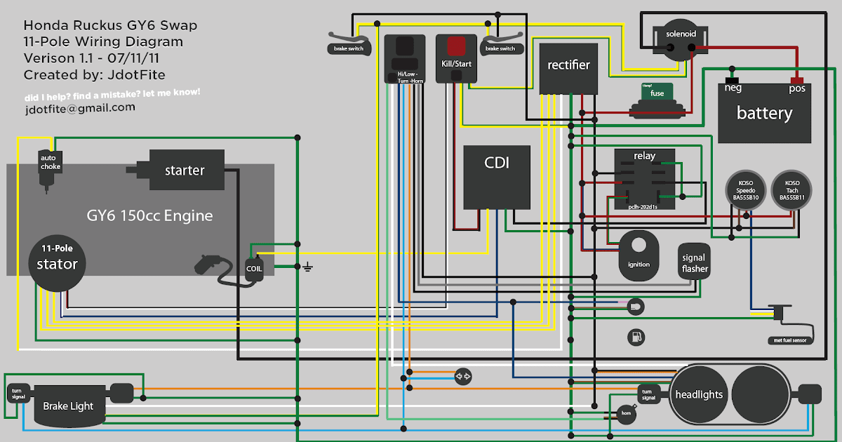
- Components: The wiring diagram identifies and locates all electrical components in the ATV, including the battery, starter solenoid, ignition coil, voltage regulator, and lighting system.
- Connections: The diagram shows how the electrical components are connected to each other, including the routing of wires and the use of connectors and terminals.
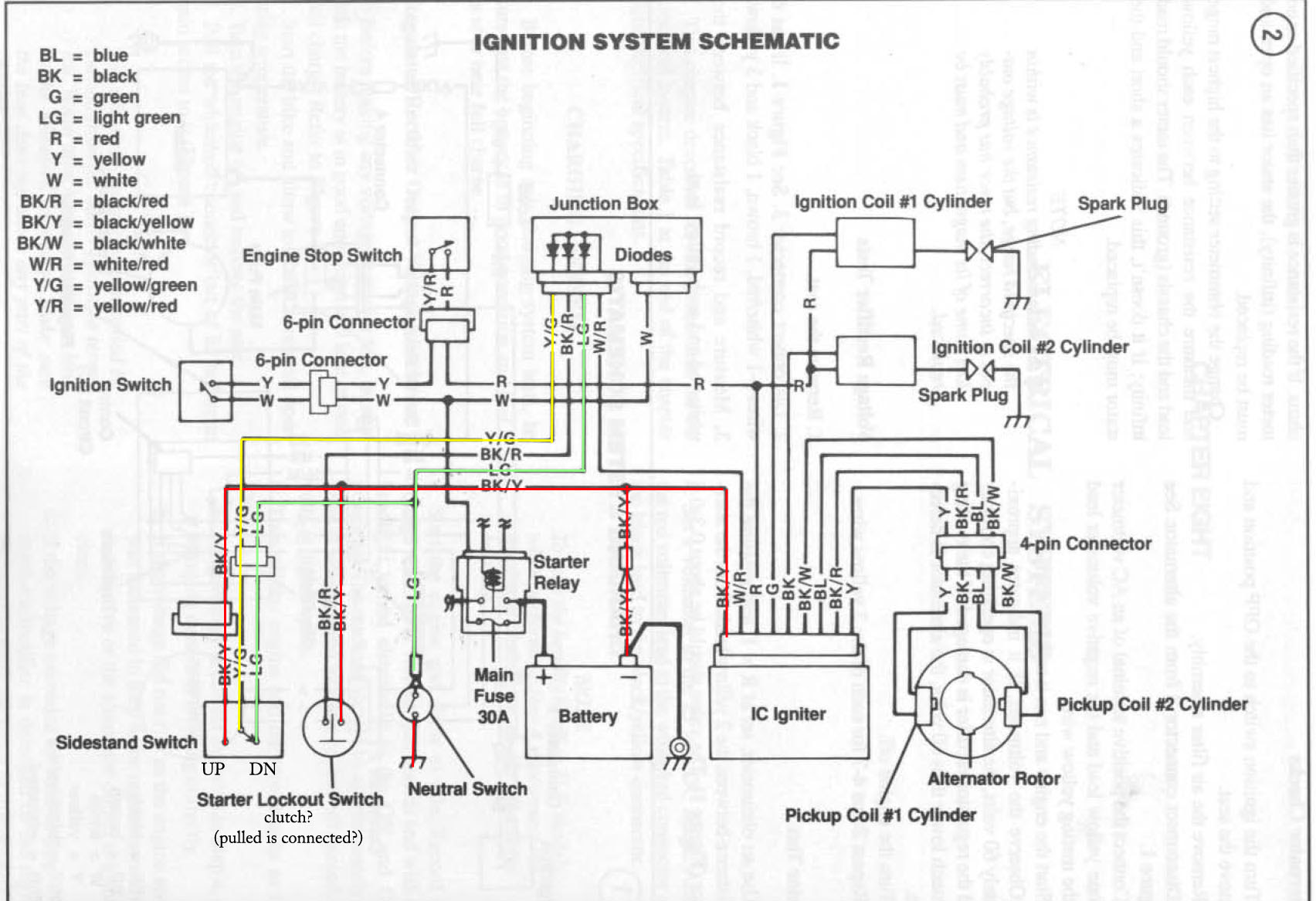
- Color Coding: Many wiring diagrams use color-coded wires to simplify identification and tracing. The diagram will provide a legend explaining the color coding scheme.
- Fuses and Relays: The diagram indicates the location and function of fuses and relays, which protect the electrical system from overcurrent and provide control over electrical circuits.
- Ground Connections: The diagram shows the location of grounding points, which are essential for completing electrical circuits and preventing electrical interference.
- Troubleshooting: The wiring diagram can be used to diagnose electrical problems by tracing circuits and identifying potential points of failure.
- Modifications: The diagram can be used as a guide for modifying the electrical system, such as adding accessories or upgrading lighting.
- Maintenance: The wiring diagram can assist in routine maintenance tasks, such as replacing fuses or inspecting wire connections.
- Safety: Understanding the wiring diagram is essential for ensuring the safe operation of the ATV’s electrical system.
- Documentation: The wiring diagram serves as a valuable documentation resource for the ATV, providing a permanent record of the electrical system’s design and configuration.
These aspects of the Kawasaki Bayou 250 Wiring Diagram are interconnected and essential for the proper functioning and maintenance of the ATV’s electrical system. By understanding these aspects, ATV owners and technicians can effectively diagnose, repair, and modify the electrical system, ensuring the safe and reliable operation of the vehicle.
Components
The “Components” aspect of the Kawasaki Bayou 250 Wiring Diagram is crucial as it provides a comprehensive overview of the electrical system’s components and their locations. This information is vital for troubleshooting electrical issues, performing repairs, and understanding the overall functionality of the ATV’s electrical system.
- Battery: The battery is the power source for the ATV’s electrical system, providing electricity to start the engine and power various electrical components. The wiring diagram indicates the battery’s location and its connections to other components.
- Starter Solenoid: The starter solenoid is an electromagnetic switch that engages the starter motor to start the engine. The wiring diagram shows the solenoid’s location and its connections to the battery, starter motor, and ignition switch.
- Ignition Coil: The ignition coil generates the high-voltage spark required to ignite the air-fuel mixture in the engine’s cylinders. The wiring diagram indicates the coil’s location and its connections to the ignition module, spark plugs, and battery.
- Voltage Regulator: The voltage regulator ensures that the electrical system maintains a stable voltage, preventing damage to electrical components. The wiring diagram shows the regulator’s location and its connections to the battery, alternator, and other electrical components.
Understanding the location and function of these components through the wiring diagram empowers ATV owners and technicians to diagnose and resolve electrical problems effectively. It also aids in modifications to the electrical system, such as adding accessories or upgrading lighting, by providing a clear understanding of the system’s architecture and potential integration points.
Connections
The “Connections” aspect of the Kawasaki Bayou 250 Wiring Diagram plays a pivotal role in understanding the flow of electricity and the interactions between electrical components within the ATV’s electrical system. This information is crucial for troubleshooting electrical faults, performing repairs, and modifying the system.
- Wiring Harness: The wiring harness is a bundle of wires that connects the various electrical components in the ATV. The wiring diagram provides a detailed layout of the wiring harness, indicating the routing of each wire, its color coding, and its connection points.
- Connectors and Terminals: Connectors and terminals are used to join wires and connect them to electrical components. The wiring diagram shows the location and type of connectors and terminals used in the ATV’s electrical system, enabling technicians to identify and troubleshoot connection issues.
- Ground Connections: Ground connections are essential for completing electrical circuits and preventing electrical interference. The wiring diagram indicates the location of grounding points, ensuring proper grounding of electrical components.
- Circuit Protection: The wiring diagram shows the location and function of fuses and circuit breakers, which protect the electrical system from overcurrent and short circuits.
By understanding the connections between electrical components through the wiring diagram, ATV owners and technicians can effectively diagnose and resolve electrical problems. This knowledge also aids in modifying the electrical system by adding accessories or upgrading components, ensuring that new additions are properly integrated and connected.
Color Coding
Understanding color coding is essential when interpreting a Kawasaki Bayou 250 Wiring Diagram. Color-coded wires are used to simplify the identification and tracing of electrical connections, making it easier to troubleshoot and repair electrical problems. The wiring diagram provides a legend that explains the color coding scheme, typically indicating the function or purpose of each wire color.
For example, in the Kawasaki Bayou 250 Wiring Diagram, red wires are generally used for positive power connections, black wires for negative or ground connections, and yellow wires for lighting circuits. By following the color coding scheme, technicians can quickly identify the purpose of a wire and trace its connections throughout the electrical system.
The use of color coding in the Kawasaki Bayou 250 Wiring Diagram streamlines the process of electrical troubleshooting. By visually identifying the function of each wire based on its color, technicians can narrow down potential issues and locate faults more efficiently. This reduces diagnostic time and simplifies repairs, ensuring the ATV’s electrical system operates correctly.
In summary, color coding in the Kawasaki Bayou 250 Wiring Diagram plays a critical role in simplifying electrical system maintenance and repairs. It provides a standardized method for identifying wire functions and tracing connections, enabling technicians to troubleshoot and resolve electrical issues effectively.
Fuses and Relays
In the Kawasaki Bayou 250 Wiring Diagram, the section on fuses and relays holds significant importance in understanding the electrical system’s protection and control mechanisms. Fuses and relays play crucial roles in safeguarding components, preventing electrical faults, and enabling efficient operation of the ATV’s electrical system.
- Fuse Protection: Fuses are designed to interrupt electrical circuits when excessive current flows, protecting sensitive electrical components from damage. The wiring diagram indicates the location and amperage rating of each fuse, providing a clear understanding of the protected circuits and the appropriate fuse selection for replacement.
- Relay Control: Relays are electromagnetic switches that use a low-power circuit to control a higher-power circuit. The wiring diagram shows the location and function of relays, enabling technicians to identify the circuits they control and troubleshoot any issues related to relay operation.
- Circuit Isolation: Fuses and relays provide isolation between electrical circuits, preventing faults in one circuit from affecting other parts of the electrical system. The wiring diagram helps visualize this isolation and aids in diagnosing and isolating electrical problems.
- System Reliability: By protecting circuits and isolating faults, fuses and relays contribute to the overall reliability of the ATV’s electrical system. The wiring diagram provides insights into these protective measures, allowing technicians to maintain and repair the system effectively, ensuring continued safe operation of the ATV.
Understanding the location and function of fuses and relays through the Kawasaki Bayou 250 Wiring Diagram is crucial for diagnosing and resolving electrical issues, ensuring the ATV’s electrical system operates safely and efficiently. This knowledge empowers ATV owners and technicians to perform maintenance, identify faults, and make informed decisions regarding electrical system modifications.
Ground Connections
Ground connections play a crucial role in the electrical system of a Kawasaki Bayou 250 ATV, as they provide a common reference point for electrical circuits and help prevent electrical interference. Understanding the location and function of these grounding points is essential for diagnosing and resolving electrical issues, ensuring the ATV’s electrical system operates safely and efficiently.
- Chassis Ground: The chassis ground connects the electrical system to the metal frame of the ATV. This provides a low-resistance path for electrical current to flow, completing circuits and ensuring proper operation of electrical components.
- Battery Ground: The battery ground connects the negative terminal of the battery to the chassis ground. This establishes a reference point for electrical circuits and ensures that all electrical components share a common ground potential.
- Engine Ground: The engine ground connects the engine block to the chassis ground. This provides a grounding path for electrical components mounted on the engine, such as the ignition coil and sensors.
- Accessory Grounds: Accessory grounds connect electrical accessories, such as lights and winches, to the chassis ground. This ensures that these accessories have a proper ground reference and function correctly.
Ground connections are essential for the proper functioning of the Kawasaki Bayou 250 ATV’s electrical system. By providing a common reference point and preventing electrical interference, grounding points ensure that electrical circuits are completed, components operate correctly, and the ATV operates safely and reliably.
Troubleshooting
In the context of the Kawasaki Bayou 250 Wiring Diagram, the troubleshooting aspect plays a pivotal role in maintaining the ATV’s electrical system. By utilizing the wiring diagram, technicians and ATV owners can systematically diagnose and resolve electrical issues, ensuring the ATV operates safely and efficiently.
- Identifying Faulty Components: The wiring diagram provides a visual representation of the electrical system, enabling technicians to trace circuits and identify potential points of failure. This helps pinpoint faulty components, such as malfunctioning sensors, damaged wires, or loose connections.
- Tracing Circuit Pathways: The wiring diagram allows technicians to trace the pathways of electrical circuits throughout the ATV. This helps identify breaks in circuits, shorts to ground, and other issues that disrupt the flow of electricity.
- Analyzing Voltage and Continuity: Using a multimeter and the wiring diagram as a reference, technicians can measure voltage and continuity at various points in the electrical system. This helps identify voltage drops, open circuits, and other electrical problems.
- Testing Components and Circuits: The wiring diagram provides insights into the proper operation of electrical components and circuits. Technicians can use test equipment to verify the functionality of components, such as switches, relays, and sensors, and ensure that circuits are operating within specified parameters.
Overall, the troubleshooting aspect of the Kawasaki Bayou 250 Wiring Diagram empowers technicians and ATV owners to diagnose electrical problems effectively. By tracing circuits, identifying potential points of failure, and testing components, they can ensure that the ATV’s electrical system is functioning correctly and address any issues promptly, minimizing downtime and maintaining the ATV’s performance and safety.
Modifications
The Kawasaki Bayou 250 Wiring Diagram serves as a valuable guide for modifying the electrical system to enhance the ATV’s functionality and performance. Whether it’s adding accessories to improve convenience or upgrading lighting for better visibility, the wiring diagram provides a comprehensive overview of the electrical system, enabling informed decision-making and proper execution of modifications.
- Accessory Integration: The wiring diagram helps identify suitable connection points for adding accessories such as winches, GPS units, or heated grips. It provides insights into the electrical requirements of these accessories and ensures their compatibility with the ATV’s electrical system.
- Lighting Upgrades: For improved visibility during night rides or in low-light conditions, the wiring diagram guides the installation of upgraded lighting systems. It indicates the appropriate wiring connections for LED headlights, auxiliary lights, or light bars, ensuring optimal performance and safety.
- Electrical System Enhancements: Modifications may extend beyond accessories and lighting to include upgrades to the electrical system itself. The wiring diagram facilitates the installation of performance-oriented components such as high-output alternators, voltage regulators, or ignition systems, optimizing the ATV’s electrical capabilities.
- Custom Wiring Projects: The wiring diagram also serves as a roadmap for custom wiring projects. It allows technicians to create custom circuits for unique electrical modifications, such as installing additional gauges, controlling aftermarket devices, or integrating custom lighting configurations.
By utilizing the Kawasaki Bayou 250 Wiring Diagram as a guide, ATV owners and technicians can confidently modify the electrical system to suit their specific needs and preferences. It empowers them to enhance the ATV’s functionality, safety, and overall riding experience through informed decision-making and precise execution of electrical modifications.
Maintenance
The Kawasaki Bayou 250 Wiring Diagram is an essential tool for maintaining the ATV’s electrical system. It provides a visual representation of the electrical components and their connections, enabling technicians and ATV owners to perform routine maintenance tasks efficiently and accurately.
Replacing fuses is a common maintenance task that requires an understanding of the wiring diagram. The diagram indicates the location and amperage rating of each fuse, ensuring that the correct fuse is selected for replacement. By utilizing the wiring diagram, technicians can quickly identify blown fuses and restore electrical functionality to the affected circuits.
Inspecting wire connections is another important maintenance task. Loose or damaged wire connections can lead to electrical problems, such as intermittent operation or complete failure of electrical components. The wiring diagram provides a systematic approach to inspecting wire connections, allowing technicians to visually trace each wire and identify any loose terminals, damaged insulation, or corrosion.
Understanding the Kawasaki Bayou 250 Wiring Diagram empowers ATV owners and technicians to perform routine maintenance tasks with confidence. By following the diagram, they can ensure that the electrical system is functioning correctly, preventing potential electrical issues and maintaining the ATV’s optimal performance.
Safety
The Kawasaki Bayou 250 Wiring Diagram is not merely a technical document but a crucial component in ensuring the safe operation of the ATV’s electrical system. Understanding the wiring diagram empowers ATV owners and technicians to identify and resolve electrical issues, preventing potential hazards and maintaining optimal performance.
A thorough understanding of the wiring diagram enables technicians to trace electrical circuits, identify potential failure points, and diagnose problems accurately. This knowledge is critical in preventing electrical fires, which can cause significant damage to the ATV and pose a safety risk to the rider.
Furthermore, the wiring diagram provides insights into the proper installation and maintenance of electrical components. By following the diagram, technicians can ensure that electrical connections are secure, wires are routed correctly, and components are functioning as intended. This attention to detail minimizes the risk of electrical malfunctions, such as short circuits or overheating, which could compromise the ATV’s safety.
In summary, the Kawasaki Bayou 250 Wiring Diagram is an essential tool for maintaining the safety and reliability of the ATV’s electrical system. By understanding the wiring diagram, ATV owners and technicians can proactively address electrical issues, prevent potential hazards, and ensure the ATV operates as intended.
Documentation
Within the context of the Kawasaki Bayou 250 Wiring Diagram, the documentation aspect plays a critical role in preserving and communicating information about the electrical system’s design and configuration. This permanent record serves as an invaluable resource for various stakeholders, including ATV owners, technicians, and enthusiasts.
- Historical Reference: The wiring diagram provides a snapshot of the electrical system’s design at a specific point in time. It serves as a valuable historical reference for understanding the evolution of the ATV’s electrical system and its components over time.
- Troubleshooting and Repair: In the event of electrical issues, the wiring diagram serves as a comprehensive guide for troubleshooting and repair. Technicians can use the diagram to trace circuits, identify faulty components, and determine the appropriate repair procedures.
- Modifications and Upgrades: For ATV enthusiasts looking to modify or upgrade their electrical systems, the wiring diagram is an essential resource. It provides insights into the existing electrical architecture, enabling informed decisions about potential modifications and ensuring compatibility with new components.
- Maintenance and Safety: The wiring diagram assists in routine maintenance tasks, such as inspecting wire connections and replacing electrical components. By providing a clear understanding of the electrical system layout, it helps ensure proper maintenance and safe operation of the ATV.
Overall, the documentation aspect of the Kawasaki Bayou 250 Wiring Diagram is an indispensable resource for understanding, maintaining, and modifying the ATV’s electrical system. Its permanent record of the electrical system’s design and configuration empowers ATV owners, technicians, and enthusiasts to effectively manage the electrical system throughout the ATV’s lifespan, ensuring optimal performance, safety, and longevity.


Related Posts


