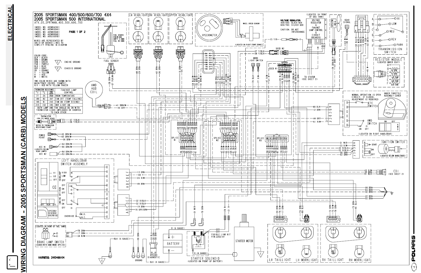
A wiring diagram for a Polaris Sportsman 500 is a technical guide that visually depicts the electrical connections and components within the all-terrain vehicle (ATV). It illustrates how different electrical components are interconnected, allowing users to diagnose electrical issues and troubleshoot malfunctions more efficiently. The diagram provides a detailed representation of wire colors, harness routing, connectors, and fuses, ensuring accurate electrical repairs and modifications.
Wiring diagrams are crucial for maintaining and repairing ATVs as they simplify the complex electrical system and enable users to understand how the electrical components work together. They provide a comprehensive overview of the electrical circuits, making it easier to identify faulty connections, shorts, or open circuits. Moreover, wiring diagrams contribute to the safe operation and reliability of the ATV by ensuring proper electrical functioning and preventing electrical hazards.
The development of standardized wiring diagrams facilitated the understanding and troubleshooting of electrical systems across multiple ATV models. This standardization enhanced the accessibility and usability of wiring diagrams for both professional technicians and ATV enthusiasts. As a result, it streamlined the repair process and made it more manageable for individuals to maintain their own ATVs.
Wiring diagrams for Polaris Sportsman 500 ATVs are comprehensive technical documents that play a vital role in understanding, maintaining, and troubleshooting the electrical system of the vehicle. These diagrams visually depict the intricate network of electrical components and their interconnections, providing valuable insights into the ATV’s electrical architecture. Understanding the key aspects of wiring diagrams is essential for effectively utilizing them for electrical diagnostics and repairs.
- Circuit Identification: Wiring diagrams clearly identify and label individual electrical circuits, making it easier to trace and isolate electrical problems.
- Component Location: They provide a visual representation of the physical location of electrical components, simplifying the process of identifying and accessing them for maintenance or replacement.
- Wire Color Coding: Wiring diagrams use color-coded lines to represent different wires, enabling technicians to quickly identify and trace wires throughout the electrical system.
- Connector Identification: They detail the types and locations of electrical connectors, ensuring proper mating and preventing connection errors.
- Fuse and Relay Identification: Wiring diagrams indicate the location and amperage of fuses and relays, allowing for quick identification and replacement of faulty components.
- Grounding Points: They show the location of grounding points, which are crucial for maintaining proper electrical function and preventing electrical hazards.
- Accessory Wiring: Wiring diagrams often include instructions for installing and wiring additional accessories, such as lights, winches, or GPS devices.
- Troubleshooting Guide: Some wiring diagrams incorporate troubleshooting guides that provide step-by-step instructions for diagnosing and resolving common electrical issues.
- Safety Precautions: They emphasize safety precautions, such as disconnecting the battery before performing electrical work, to prevent electrical shocks or accidents.
- Model Specificity: Wiring diagrams are specific to each Polaris Sportsman 500 model year, ensuring accuracy and relevance for the particular ATV being serviced.
In summary, wiring diagrams for Polaris Sportsman 500 ATVs are essential tools that provide a comprehensive understanding of the electrical system. They enable technicians and enthusiasts to diagnose electrical issues, perform repairs, and modify electrical components with confidence. By utilizing these diagrams effectively, individuals can maintain the electrical integrity of their ATVs, ensuring safe and reliable operation.
Circuit Identification
Within the context of “Wiring Diagram for Polaris Sportsman 500”, circuit identification plays a pivotal role in electrical troubleshooting and repair. Wiring diagrams meticulously identify and label each electrical circuit, providing a clear and organized visual representation of the ATV’s electrical system. This allows technicians and enthusiasts to quickly trace and isolate electrical problems, minimizing downtime and ensuring efficient repairs.
- Labeled Circuit Components: Wiring diagrams label individual components within each circuit, such as switches, relays, sensors, and actuators. This labeling simplifies the identification of faulty components and enables targeted troubleshooting.
- Color-Coded Wiring: Many wiring diagrams utilize color-coded lines to represent different circuits. This color-coding corresponds to the actual wire colors used in the ATV’s electrical system, allowing technicians to easily trace wires and identify their respective circuits.
- Circuit Grouping: Wiring diagrams often group related circuits together, such as lighting circuits, ignition circuits, and fuel injection circuits. This grouping facilitates the identification of common issues within specific systems.
- Test Points: Some wiring diagrams include designated test points for each circuit. These test points allow technicians to use a multimeter or other diagnostic tools to measure voltage, resistance, or continuity, aiding in the isolation of electrical faults.
In summary, circuit identification in wiring diagrams for Polaris Sportsman 500 ATVs provides a systematic approach to electrical troubleshooting. By clearly identifying and labeling individual circuits and their components, wiring diagrams empower technicians and enthusiasts to trace and isolate electrical problems with greater accuracy and efficiency. This ultimately leads to reduced repair times, improved reliability, and enhanced safety for ATV users.
Component Location
Within the context of “Wiring Diagram for Polaris Sportsman 500”, component location plays a crucial role in ensuring efficient maintenance and repairs. Wiring diagrams provide a visual representation of the physical location of electrical components, enabling technicians and enthusiasts to quickly identify and access components for various purposes, including troubleshooting, maintenance, and replacement.
- Precise Component Identification: Wiring diagrams accurately depict the location of each electrical component, including sensors, relays, actuators, and modules. This precise identification simplifies the process of identifying specific components, especially when dealing with complex electrical systems.
- Real-Life Example: For instance, if the brake light on a Polaris Sportsman 500 ATV malfunctions, the wiring diagram can guide the technician directly to the brake light switch, enabling quick troubleshooting and replacement.
- Simplified Maintenance: Wiring diagrams assist in routine maintenance tasks, such as replacing spark plugs or cleaning electrical connectors. By visually locating the component, technicians can minimize time spent searching and maximize efficiency.
- Enhanced Accessibility: Wiring diagrams provide insights into the accessibility of components. They indicate whether components are easily accessible or require the removal of other components or panels. This information helps technicians plan maintenance and repair strategies effectively.
In summary, the component location aspect of wiring diagrams for Polaris Sportsman 500 ATVs serves as an invaluable tool for maintaining and repairing the electrical system. By providing a visual representation of the physical location of electrical components, wiring diagrams empower technicians and enthusiasts to work with greater accuracy, efficiency, and confidence, ensuring the optimal performance and reliability of their ATVs.
Wire Color Coding
In the context of “Wiring Diagram For Polaris Sportsman 500”, wire color coding plays a fundamental role in simplifying the identification and tracing of electrical wires throughout the ATV’s electrical system. Wiring diagrams utilize a standardized color-coding scheme to differentiate between different wires, making it easier for technicians and enthusiasts to navigate the complex network of electrical connections.
- Simplified Wire Identification: Color coding allows technicians to quickly identify specific wires based on their color, eliminating the need to manually trace each wire individually. This is especially useful when dealing with large wiring harnesses or when wires are bundled together.
- Real-Life Example: For instance, in a Polaris Sportsman 500 ATV, the red wire is typically used for positive power connections, while the black wire is used for negative ground connections. This color-coding convention enables technicians to easily identify power and ground wires, even in complex circuits.
- Reduced Troubleshooting Time: Color coding facilitates faster troubleshooting by allowing technicians to trace wires more efficiently. By following the color-coded lines on the wiring diagram, they can quickly identify the source of electrical faults or malfunctions.
- Improved Electrical System Modifications: Color coding also simplifies the process of making modifications to the electrical system. By matching the color of the new wire to the corresponding color-coded line on the wiring diagram, technicians can ensure proper connections and maintain the integrity of the electrical system.
In summary, the wire color coding aspect of wiring diagrams for Polaris Sportsman 500 ATVs provides significant benefits by enabling quick and accurate wire identification, reducing troubleshooting time, and simplifying electrical system modifications. This color-coding scheme is an essential tool for maintaining and repairing the electrical system, contributing to the overall reliability and performance of the ATV.
Connector Identification
Within the context of “Wiring Diagram for Polaris Sportsman 500”, connector identification plays a crucial role in ensuring the proper functioning and reliability of the ATV’s electrical system. Wiring diagrams meticulously detail the types and locations of electrical connectors, providing vital information for technicians and enthusiasts to correctly mate and connect electrical components.
Connector identification is critical because electrical connectors establish secure and reliable electrical connections between different components within the ATV’s electrical system. Without proper connector identification, technicians may encounter difficulties in mating connectors correctly, leading to connection errors, malfunctions, or even electrical hazards.
- Real-Life Example: The Polaris Sportsman 500 ATV utilizes various types of electrical connectors, including bullet connectors, spade connectors, and multi-pin connectors. Wiring diagrams clearly identify the type of connector used for each connection point, enabling technicians to select the appropriate mating connector.
- Prevention of Connection Errors: By providing precise information on connector types and locations, wiring diagrams help prevent connection errors that could arise from incorrect mating. This reduces the risk of electrical shorts, open circuits, or intermittent connections, ensuring the ATV’s electrical system operates as intended.
- Simplified Troubleshooting: Accurate connector identification simplifies troubleshooting electrical issues. When a malfunction occurs, technicians can refer to the wiring diagram to quickly identify the affected connector and check for proper mating, loose connections, or damaged terminals.
Furthermore, connector identification facilitates modifications and upgrades to the electrical system. When adding accessories or replacing electrical components, technicians can use the wiring diagram to determine the correct connector type and location for a secure and reliable connection.
In summary, connector identification within wiring diagrams for Polaris Sportsman 500 ATVs is a critical component for maintaining a properly functioning electrical system. By providing precise information on connector types and locations, wiring diagrams empower technicians and enthusiasts to make accurate connections, prevent errors, and troubleshoot issues effectively, contributing to the overall safety, reliability, and performance of the ATV.
Fuse and Relay Identification
Within the context of “Wiring Diagram For Polaris Sportsman 500”, fuse and relay identification plays a crucial role in maintaining a reliable and safe electrical system. Wiring diagrams provide precise information on the location and amperage of fuses and relays, enabling technicians and enthusiasts to quickly identify and replace faulty components, minimizing downtime and ensuring optimal performance.
- Fuse Identification and Protection: Wiring diagrams clearly indicate the location and amperage of fuses, which serve as protective devices in the electrical system. By identifying the correct fuse for a particular circuit, technicians can quickly replace blown fuses and restore power, preventing damage to electrical components.
- Relay Function and Control: Wiring diagrams provide insights into the location and function of relays, which are electromagnetic switches that control the flow of electrical current in various circuits. By understanding the role of each relay, technicians can troubleshoot electrical issues related to component activation, power distribution, and circuit protection.
- Real-Life Example: The Polaris Sportsman 500 ATV’s fuel pump relay is a critical component that controls the operation of the fuel pump. Wiring diagrams indicate the location of this relay and its connection to the ignition switch and fuel pump circuit, enabling technicians to diagnose and resolve issues related to fuel delivery.
- Implications for Electrical System Integrity: Accurate fuse and relay identification is essential for maintaining the integrity of the electrical system. Using incorrect fuses or relays can lead to electrical overloads, damage to components, or even electrical fires. Wiring diagrams provide the necessary information to ensure proper fuse and relay selection and replacement.
In summary, fuse and relay identification within wiring diagrams for Polaris Sportsman 500 ATVs is a vital aspect for maintaining a reliable and safe electrical system. By providing precise information on the location and amperage of fuses and relays, wiring diagrams empower technicians and enthusiasts to quickly identify and replace faulty components, troubleshoot electrical issues, and ensure optimal performance of the ATV.
Grounding Points
Within the context of “Wiring Diagram for Polaris Sportsman 500,” grounding points play a critical role in ensuring the proper functioning and safety of the ATV’s electrical system. Wiring diagrams provide precise information on the location of grounding points, which are crucial for maintaining a stable electrical reference and preventing electrical hazards.
Grounding points establish a common reference point for electrical circuits, allowing current to flow properly and preventing voltage fluctuations. Without proper grounding, electrical circuits can malfunction, leading to component damage, erratic behavior, or even electrical shocks. Wiring diagrams clearly indicate the location of grounding points, enabling technicians and enthusiasts to ensure that all electrical components are correctly grounded.
Real-life examples of grounding points in a Polaris Sportsman 500 ATV include the negative terminal of the battery, the engine block, and the frame of the ATV. These grounding points provide a low-resistance path for electrical current to return to the source, completing electrical circuits and preventing voltage spikes.
The practical significance of understanding grounding points lies in the prevention of electrical hazards. Improper grounding can lead to electrical shorts, which can cause fires or damage to electrical components. By providing the location of grounding points, wiring diagrams empower technicians and enthusiasts to maintain a safe and reliable electrical system.
In summary, grounding points are crucial components of any electrical system, including the Polaris Sportsman 500 ATV. Wiring diagrams provide essential information on the location of grounding points, enabling proper electrical grounding and preventing electrical hazards. Understanding the importance of grounding points is critical for maintaining the safety, reliability, and performance of the ATV’s electrical system.
Accessory Wiring
Within the context of “Wiring Diagram For Polaris Sportsman 500”, accessory wiring plays a significant role in expanding the functionality and customization of the ATV. Wiring diagrams provide detailed instructions and guidance on how to properly install and wire additional accessories, enabling enthusiasts to enhance their ATV’s capabilities and adapt it to their specific needs.
The connection between accessory wiring and wiring diagrams for Polaris Sportsman 500 ATVs is critical because it ensures the safe and effective integration of additional electrical components into the ATV’s electrical system. By following the instructions provided in the wiring diagram, users can avoid potential electrical hazards, such as short circuits or overloading the electrical system, which can lead to damage or malfunctions.
Real-life examples of accessory wiring in the context of Polaris Sportsman 500 ATVs include the installation of additional lighting systems, such as LED light bars or auxiliary spotlights, to improve visibility during night riding or in low-light conditions. Wiring diagrams provide step-by-step instructions on how to connect these lights to the ATV’s electrical system, ensuring proper power supply and functionality.
Another practical application of accessory wiring is the integration of winches into Polaris Sportsman 500 ATVs. Winches are essential tools for off-road enthusiasts, enabling them to pull the ATV out of challenging terrain or assist in recovery situations. Wiring diagrams provide detailed instructions on how to wire the winch motor and control system to the ATV’s battery and electrical system, ensuring safe and reliable operation.
In summary, the connection between accessory wiring and wiring diagrams for Polaris Sportsman 500 ATVs is crucial for the safe and effective installation and integration of additional accessories. Wiring diagrams empower users to customize their ATVs, enhance their functionality, and adapt them to their specific needs, while ensuring the integrity and reliability of the ATV’s electrical system.
Troubleshooting Guide
Within the context of “Wiring Diagram For Polaris Sportsman 500,” a troubleshooting guide plays a critical role in empowering users to diagnose and resolve electrical issues efficiently and effectively. Wiring diagrams that incorporate troubleshooting guides provide a comprehensive resource for both professional technicians and ATV enthusiasts to identify and rectify electrical faults, minimizing downtime and ensuring optimal performance.
The significance of a troubleshooting guide within a wiring diagram for Polaris Sportsman 500 ATVs lies in its ability to simplify the troubleshooting process, especially for individuals with limited electrical experience. These guides provide step-by-step instructions that guide users through a series of diagnostic tests, allowing them to pinpoint the root cause of electrical problems.
Real-life examples of troubleshooting guides within wiring diagrams for Polaris Sportsman 500 ATVs include procedures for diagnosing and resolving common issues such as:
- Electrical component malfunctions (e.g., faulty sensors, switches, or relays)
- Wiring harness problems (e.g., broken wires, loose connections, or shorts)
- Battery and charging system issues (e.g., weak battery, alternator problems, or faulty voltage regulator)
- Ignition system faults (e.g., spark plug issues, ignition coil problems, or faulty ignition module)
- Fuel injection system problems (e.g., clogged injectors, faulty fuel pump, or sensor malfunctions)
The practical significance of understanding and utilizing troubleshooting guides within wiring diagrams for Polaris Sportsman 500 ATVs extends beyond basic repairs. By empowering users to diagnose and resolve electrical issues independently, these guides promote self-reliance and reduce the need for costly repairs at authorized service centers. Furthermore, the troubleshooting process enhances users’ understanding of the ATV’s electrical system, enabling them to make informed decisions regarding maintenance and modifications.
In summary, the integration of troubleshooting guides within wiring diagrams for Polaris Sportsman 500 ATVs is a valuable resource that empowers users to diagnose and resolve electrical issues efficiently. These guides provide a systematic approach to troubleshooting, reducing downtime and promoting self-reliance. By understanding the principles of electrical troubleshooting, ATV owners can maintain and repair their vehicles with greater confidence, ensuring optimal performance and safety.
Safety Precautions
Within the context of “Wiring Diagram for Polaris Sportsman 500”, safety precautions play a critical role in ensuring the well-being of individuals working on the ATV’s electrical system. Wiring diagrams emphasize these precautions, providing clear instructions and reminders to prevent electrical shocks, accidents, and potential damage to electrical components.
-
Disconnecting the Battery:
Before performing any electrical work, it is crucial to disconnect the battery to eliminate any potential electrical current flow. This simple step effectively prevents accidental shocks or short circuits that could arise when working on electrical components.
-
Proper Tool Usage:
Using the appropriate tools for electrical work is essential. Insulated tools, non-conductive gloves, and safety glasses help protect against electrical shocks and prevent accidental damage to components.
-
Adequate Lighting and Ventilation:
Working in a well-lit area with proper ventilation ensures clear visibility and reduces the risk of accidents. Adequate lighting allows for precise identification of wires and components, while good ventilation helps dissipate any fumes or odors that may arise during electrical work.
-
Understanding Electrical Hazards:
Recognizing and understanding potential electrical hazards is crucial. This includes being aware of the different types of electrical hazards, such as live wires, high voltage, and electrical arcs, and taking appropriate precautions to avoid them.
By adhering to the safety precautions outlined in wiring diagrams, individuals can approach electrical work on their Polaris Sportsman 500 ATVs with greater confidence and reduce the likelihood of accidents or injuries. These precautions not only protect the safety of the individuals performing the work but also contribute to the longevity and reliability of the ATV’s electrical system.
Model Specificity
Within the context of “Wiring Diagram For Polaris Sportsman 500,” model specificity plays a critical role in ensuring the accuracy and effectiveness of electrical repairs, maintenance, and modifications. Wiring diagrams are meticulously tailored to each Polaris Sportsman 500 model year, taking into account the unique electrical configurations, component variations, and potential modifications specific to each model.
-
Distinct Electrical Configurations:
Each model year of the Polaris Sportsman 500 may introduce subtle or significant changes to the ATV’s electrical system. Model-specific wiring diagrams provide accurate representations of these variations, ensuring that technicians and enthusiasts have the correct schematics for the particular ATV they are working on.
-
Component Variations:
Polaris Sportsman 500 ATVs may feature different electrical components depending on the model year, such as variations in sensors, actuators, or control modules. Model-specific wiring diagrams account for these component variations, providing precise information on the location, function, and wiring connections for each component.
-
Compatibility with Modifications:
As ATV enthusiasts customize their vehicles, model-specific wiring diagrams become essential for ensuring compatibility with aftermarket accessories and modifications. These diagrams help identify potential conflicts or compatibility issues, enabling informed decisions and preventing electrical problems.
-
Real-Life Example:
For instance, a 2015 Polaris Sportsman 500 EPS model may have a different wiring configuration for the electronic power steering system compared to a 2017 model. Using a model-specific wiring diagram ensures that the correct wiring procedures and component identification are followed, preventing errors and potential damage.
In summary, model specificity in wiring diagrams for Polaris Sportsman 500 ATVs is crucial for accurate electrical diagnostics, repairs, and modifications. By providing model-specific schematics, wiring diagrams empower technicians and enthusiasts to work with confidence, ensuring the reliability, safety, and optimal performance of their ATVs.


![[DIAGRAM] Polaris Sportsman Wiring Diagrams](https://i0.wp.com/parts.polarisind.com/images/ATV/HARNESS/08SP500.gif?w=665&ssl=1)


Related Posts


