A series wiring diagram illustrates how electrical components are connected in a sequence, with the output of one component feeding directly into the input of the next. A prevalent example is a string of holiday lights, where each bulb is connected in series, causing all bulbs to turn off if one bulb fails.
Series wiring is essential for various applications, including controlling the flow of current in circuits, enabling the use of multiple components with varying voltages, and facilitating the distribution of power over long distances. A significant historical development was Thomas Edison’s invention of the series circuit in 1879, which revolutionized electrical distribution systems.
This article will delve into the intricacies of series wiring diagrams, exploring their components, principles of operation, and practical applications in diverse electrical systems.
The essential aspects of a series wiring diagram, a blueprint for connecting electrical components in a sequential manner, are crucial for understanding its functionality, implementation, and applications. These aspects encompass:
- Components
- Circuit
- Current
- Flow
- Power
- Resistance
- Voltage
- Wattage
- Connections
Understanding these key aspects enables a comprehensive grasp of series wiring diagrams, their behavior, and their significance in electrical systems. They dictate the flow of current, voltage distribution, power consumption, and overall functionality of the circuit. By carefully considering each aspect and its relationship to the others, engineers and electricians can design and implement efficient and reliable electrical systems.
Components
In the realm of series wiring diagrams, components play a pivotal role in shaping the circuit’s behavior and functionality. These components, akin to the building blocks of an electrical system, determine the flow of current, voltage distribution, and overall performance of the circuit.
-
Resistors
Resistors impede the flow of current, regulating the amount of electrical energy dissipated as heat. Their resistance value, measured in ohms, directly influences the current flow and voltage drop across the resistor.
-
Capacitors
Capacitors store electrical energy in an electric field, acting as a reservoir of charge. They can smooth out voltage fluctuations, filter out unwanted frequencies, and store energy for later release.
-
Inductors
Inductors oppose changes in current flow, storing energy in a magnetic field. They can smooth out current fluctuations, filter out unwanted frequencies, and store energy for later release.
-
Diodes
Diodes allow current to flow in only one direction, preventing reverse current flow. They are commonly used for rectification, voltage regulation, and signal processing.
These components, when combined in a series configuration, create a circuit where the current flows through each component sequentially, resulting in a cumulative voltage drop and a shared current strength. Understanding the characteristics and interactions of these components is paramount for designing and analyzing series wiring diagrams.
Circuit
Within the realm of electrical engineering, a circuit is a fundamental concept that underpins the design and analysis of electrical systems. A circuit provides a structured pathway for the flow of electrical current, enabling the transfer of energy from a source to various components and ultimately to a load. In the context of series wiring diagrams, understanding the concept of a circuit is crucial for comprehending how electrical components are interconnected and how current flows through them.
A series wiring diagram is a graphical representation of a circuit that specifically depicts components connected in a sequential manner, one after the other. In a series circuit, the current has only one path to follow, passing through each component in turn. This arrangement results in a cumulative voltage drop across the components, while the current strength remains constant throughout the circuit. The simplicity and predictability of series circuits make them commonly used in various applications, such as lighting, battery packs, and voltage dividers.
The relationship between circuit and series wiring diagram is therefore inseparable. A series wiring diagram provides a visual representation of the circuit, allowing engineers and technicians to analyze and troubleshoot the system more easily. By understanding the circuit’s topology and the behavior of current flow, they can design and implement electrical systems that meet specific requirements for voltage, current, and power.
In summary, a circuit is a fundamental concept in electrical engineering, providing the framework for the flow of electrical current. A series wiring diagram is a specialized type of circuit diagram that depicts components connected in a series configuration, facilitating the analysis and design of electrical systems. Understanding the connection between circuit and series wiring diagram is essential for anyone seeking to comprehend the intricacies of electrical systems.
Current
Current, in the context of electrical engineering and particularly in relation to series wiring diagrams, is the flow of electric charge. It is a fundamental concept that underpins the functionality and behavior of electrical circuits. In a series wiring diagram, current plays a critical role, as it is the driving force that enables the transfer of electrical energy from the source through the components and ultimately to the load. Without current, there would be no flow of electrical energy, and the circuit would not function.
The relationship between current and series wiring diagram is bidirectional. On the one hand, a series wiring diagram provides a visual representation of the path that current takes through a circuit. By examining the diagram, engineers and technicians can trace the flow of current and identify the components that it passes through. On the other hand, the presence of current in a series circuit has a direct impact on the behavior of the circuit. The strength of the current determines the voltage drop across each component and the overall power consumption of the circuit.
Real-life examples of current in series wiring diagrams are prevalent in various applications. One common example is a string of holiday lights. In a series-wired string of lights, the current flows through each bulb in turn, causing them to illuminate. If one bulb burns out, the entire string goes dark because the current can no longer flow through the circuit. Another example is a voltage divider circuit, which uses resistors connected in series to divide the input voltage into smaller output voltages. The current flowing through the circuit determines the voltage drop across each resistor, and the output voltages are proportional to the resistance values.
Understanding the connection between current and series wiring diagrams is crucial for anyone seeking to comprehend the intricacies of electrical systems. By grasping the role of current as the driving force in a circuit, engineers and technicians can design and implement electrical systems that meet specific requirements for voltage, current, and power. Furthermore, this understanding enables them to troubleshoot and repair electrical circuits effectively, ensuring the safe and efficient operation of electrical systems in various applications.
Flow
In the realm of electrical engineering, “flow” refers to the movement of electric charge, commonly known as current. Within the context of series wiring diagrams, flow plays a pivotal role, as it represents the path that electrical current takes through a circuit. A series wiring diagram is a graphical representation of a circuit in which components are connected in a sequential manner, one after the other. In such a configuration, the current has only one path to follow, resulting in a cumulative voltage drop across the components.
The connection between flow and series wiring diagram is bidirectional. On the one hand, a series wiring diagram provides a visual representation of the flow of current through a circuit. By examining the diagram, engineers and technicians can trace the path that current takes and identify the components it passes through. This understanding is crucial for analyzing the behavior of the circuit and ensuring that it meets the desired specifications.
On the other hand, the flow of current in a series circuit has a direct impact on the behavior of the circuit. The strength of the current determines the voltage drop across each component and the overall power consumption of the circuit. By understanding the relationship between flow and series wiring diagram, engineers can design and implement electrical systems that meet specific requirements for voltage, current, and power. Furthermore, this understanding enables them to troubleshoot and repair electrical circuits effectively, ensuring the safe and efficient operation of electrical systems in various applications.
Real-life examples of flow within series wiring diagrams are prevalent in various applications. One common example is a string of holiday lights. In a series-wired string of lights, the current flows through each bulb in turn, causing them to illuminate. If one bulb burns out, the entire string goes dark because the current can no longer flow through the circuit. Another example is a voltage divider circuit, which uses resistors connected in series to divide the input voltage into smaller output voltages. The current flowing through the circuit determines the voltage drop across each resistor, and the output voltages are proportional to the resistance values.
In conclusion, the connection between flow and series wiring diagram is fundamental to understanding the behavior and functionality of electrical circuits. By comprehending the role of flow as the driving force in a circuit, engineers and technicians can design, implement, and troubleshoot electrical systems effectively. This understanding is essential for ensuring the safe and efficient operation of electrical systems in various applications.
Power
Power, within the context of series wiring diagrams, holds immense significance in understanding the behavior and functionality of electrical circuits. It represents the rate at which electrical energy is transferred or consumed, and its implications extend to various aspects of circuit design and analysis. This detailed exploration will delve into specific facets of power related to series wiring diagrams, shedding light on their roles, real-life examples, and implications.
-
Electrical Potential
Electrical potential, measured in volts, represents the difference in electrical energy between two points in a circuit. In a series wiring diagram, the potential difference across each component contributes to the overall voltage drop.
-
Current Flow
Current flow, measured in amperes, represents the movement of electric charge through a circuit. In a series wiring diagram, the current strength remains constant throughout the circuit, passing through each component in turn.
-
Resistance
Resistance, measured in ohms, represents the opposition to the flow of current in a circuit. In a series wiring diagram, the resistance of each component contributes to the overall resistance of the circuit, affecting the current flow and voltage drop.
-
Power Dissipation
Power dissipation, measured in watts, represents the conversion of electrical energy into other forms of energy, such as heat or light. In a series wiring diagram, power dissipation occurs across each component, and the total power dissipation determines the overall efficiency of the circuit.
These facets of power are intertwined, providing a comprehensive perspective on the behavior of series wiring diagrams. By understanding the relationship between power, voltage, current, resistance, and power dissipation, engineers can design and implement electrical systems that meet specific requirements for power transfer, efficiency, and safety. Additionally, these insights facilitate troubleshooting and maintenance of electrical circuits, ensuring their continued reliability and optimal performance.
Resistance
Resistance, measured in ohms, is a fundamental property of electrical components that impedes the flow of current. In the context of series wiring diagrams, resistance plays a critical role in determining the behavior and functionality of the circuit. When components are connected in series, the total resistance of the circuit is the sum of the individual resistances of each component. This cumulative resistance affects the current flow, voltage drop, and power dissipation within the circuit.
The relationship between resistance and series wiring diagrams is bidirectional. On the one hand, the resistance of each component in a series circuit directly influences the overall resistance of the circuit. By carefully selecting resistors with specific resistance values, engineers can design circuits with desired current flow and voltage drop characteristics. On the other hand, the total resistance of a series circuit has a direct impact on the behavior of the circuit. Higher resistance leads to lower current flow and higher voltage drop, while lower resistance leads to higher current flow and lower voltage drop.
Real-life examples of resistance in series wiring diagrams are prevalent in various applications. One common example is a voltage divider circuit, which uses resistors connected in series to divide the input voltage into smaller output voltages. The resistance values of the resistors determine the voltage drop across each resistor and the output voltages. Another example is a current-limiting resistor, which is connected in series with a sensitive electronic component to limit the current flow and protect the component from damage. By understanding the relationship between resistance and series wiring diagrams, engineers can design and implement electrical circuits that meet specific requirements for current flow, voltage drop, and power dissipation.
In summary, resistance is a critical component of series wiring diagrams, affecting the overall behavior and functionality of the circuit. By understanding the relationship between resistance, current flow, voltage drop, and power dissipation, engineers can design and implement electrical circuits that meet specific requirements. This understanding is essential for ensuring the safe and efficient operation of electrical systems in various applications.
Voltage
Voltage, a fundamental aspect of series wiring diagrams, plays a crucial role in determining the behavior and functionality of electrical circuits. It represents the electrical potential difference between two points in a circuit and is a driving force for the flow of current. Understanding the relationship between voltage and series wiring diagrams is essential for designing, analyzing, and troubleshooting electrical circuits.
-
Electrical Potential
Electrical potential, measured in volts, represents the difference in electrical energy between two points in a circuit. In a series wiring diagram, the potential difference across each component contributes to the overall voltage drop.
-
Current Flow
Voltage is directly related to current flow in a series circuit. Ohm’s law states that the current flowing through a conductor is directly proportional to the voltage applied across it. By controlling the voltage, engineers can control the current flow in a series circuit.
-
Power Dissipation
Voltage and current together determine the power dissipated in a series circuit. Power dissipation, measured in watts, represents the conversion of electrical energy into other forms of energy, such as heat or light. By understanding the relationship between voltage, current, and power dissipation, engineers can design circuits that operate efficiently and safely.
-
Real-Life Examples
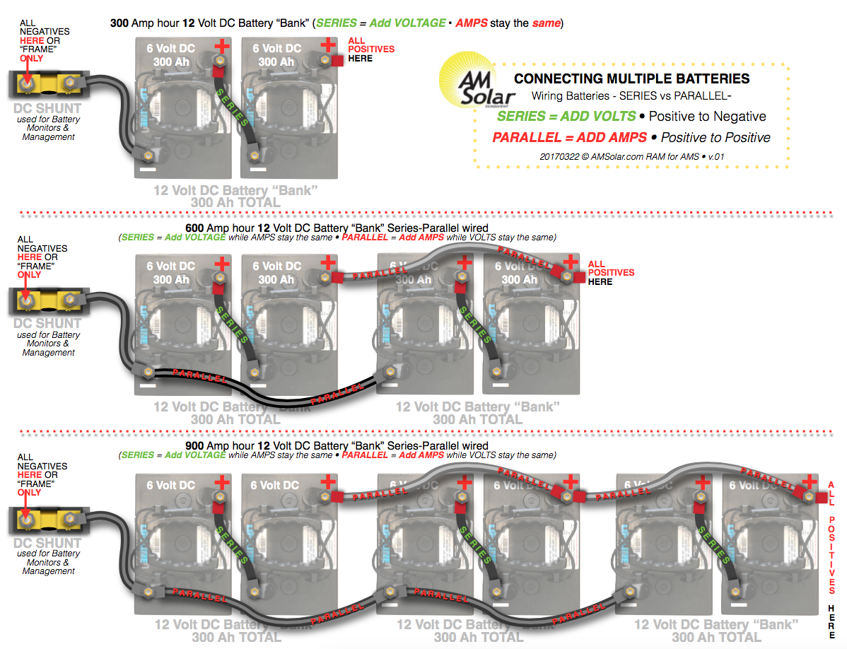
Series wiring diagrams are used in various applications, such as voltage dividers, battery packs, and lighting circuits. In a voltage divider, resistors are connected in series to divide the input voltage into smaller output voltages. In a battery pack, cells are connected in series to increase the overall voltage. In lighting circuits, bulbs are connected in series to control the brightness of the lights.
In conclusion, voltage is a critical component of series wiring diagrams, affecting the overall behavior and functionality of the circuit. By understanding the relationship between voltage, current flow, power dissipation, and real-life applications, engineers can design and implement electrical circuits that meet specific requirements for voltage, current, and power. This understanding is essential for ensuring the safe and efficient operation of electrical systems in various applications.
Wattage
Within the realm of series wiring diagrams, wattage holds significant importance as it pertains to the power consumption and energy dissipation characteristics of the circuit. Wattage, measured in watts, represents the rate at which electrical energy is transferred or consumed, providing valuable insights into the circuit’s overall efficiency and performance.
-
Power Dissipation
Wattage is directly related to power dissipation, which occurs when electrical energy is converted into other forms of energy, such as heat or light. In a series wiring diagram, the wattage of each component contributes to the total power dissipation of the circuit, influencing its overall efficiency and operating temperature.
-
Voltage and Current
Wattage is determined by the voltage and current in the circuit. According to Ohm’s law, wattage is the product of voltage and current. By understanding the relationship between voltage, current, and wattage, engineers can design circuits that operate within desired power consumption limits.
-
Resistance and Wattage Rating
The wattage rating of a component specifies the maximum amount of power it can dissipate without overheating or failing. When selecting components for a series wiring diagram, it is crucial to ensure that their wattage ratings are appropriate for the expected operating conditions.
-
Real-Life Examples
Series wiring diagrams are widely used in various applications, including lighting circuits, battery packs, and voltage dividers. In lighting circuits, the wattage of the bulbs determines the brightness of the lights. In battery packs, the wattage rating of the cells indicates their power output and capacity. Voltage dividers utilize resistors with specific wattage ratings to achieve desired voltage divisions.
In summary, wattage is a fundamental aspect of series wiring diagrams, providing insights into power consumption, energy dissipation, and component selection. By understanding the relationship between wattage, voltage, current, and resistance, engineers can design and implement electrical circuits that meet specific requirements for power efficiency, safety, and performance.
Connections
Within the realm of series wiring diagrams, connections serve as the fundamental building blocks that establish the flow of electrical current and dictate the behavior of the circuit. Each connection represents a point where two or more components are joined, forming a continuous electrical pathway. Understanding the significance of connections in series wiring diagrams is paramount for comprehending the functionality, analysis, and design of electrical systems.
Connections are not merely passive elements; they actively influence the performance of the circuit. A loose or poorly made connection can introduce resistance, leading to voltage drops and inefficient current flow. Conversely, secure and well-executed connections ensure minimal resistance, allowing for optimal current transfer and efficient power distribution. The choice of connection method, such as soldering, crimping, or screw terminals, also impacts the reliability and longevity of the circuit.
Real-life examples of connections in series wiring diagrams abound in various electrical applications. In household lighting circuits, switches and bulbs are connected in series, allowing for the control of multiple lights from a single switch. Battery packs, commonly used in portable devices, connect individual cells in series to achieve higher voltages. Moreover, complex electronic circuits employ series connections to establish signal paths, voltage dividers, and timing networks.
The practical significance of understanding connections in series wiring diagrams extends beyond theoretical knowledge. It empowers engineers and technicians to troubleshoot and repair electrical systems effectively. By identifying loose connections or faulty components, they can pinpoint the root cause of circuit malfunctions and restore functionality. Additionally, this understanding enables the design of reliable and efficient electrical systems, ensuring safety and optimal performance in various applications.


Related Posts


