An Ademco Vista 20p Wiring Diagram outlines the electrical connections, wiring specifications, and component placements for the Ademco Vista 20p security system. It provides a visual guide for installers to ensure proper system configuration and operation.
This diagram is crucial for system installation and maintenance. It enables technicians to identify and connect the correct wires to their respective terminals, reducing the risk of errors and ensuring the system’s functionality. It also facilitates troubleshooting and upgrades, enabling technicians to quickly identify and resolve any issues.
One key development in the history of wiring diagrams for security systems was the introduction of standardized color codes for different types of wires and connections. This standardization simplified the installation process, ensured consistency across systems, and reduced the potential for wiring errors.
Understanding the key aspects of an Ademco Vista 20p Wiring Diagram is crucial for successful installation and maintenance of the security system. These aspects provide a comprehensive overview of the system’s electrical connections, wiring specifications, and component placements.
- Component Identification: The diagram clearly identifies each component within the security system, including the control panel, keypad, sensors, and sirens.
- Wiring Specifications: The diagram specifies the type and gauge of wire required for each connection, ensuring proper signal transmission and system reliability.
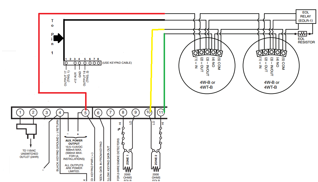
- Terminal Designations: Each terminal on the control panel and other components is clearly labeled, indicating its specific purpose and the type of connection it accepts.
- Power Requirements: The diagram outlines the power requirements for the system, including the voltage and current draw, ensuring proper power supply and system functionality.
- Grounding: Proper grounding techniques are essential for system stability and noise reduction. The diagram specifies the grounding points and connections required.
- Loop Supervision: The diagram indicates the wiring connections for loop supervision, a feature that monitors the integrity of the wiring and detects any faults or tampering attempts.
- Zone Configuration: The diagram shows how to configure the system’s zones, allowing for customized protection of different areas within the premises.
- Expansion Capabilities: The diagram outlines the options for expanding the system with additional sensors, keypads, and other devices, providing flexibility and scalability.
- Troubleshooting Guide: The diagram often includes a troubleshooting guide that provides guidance on resolving common wiring issues and system malfunctions.
- Compliance with Standards: The diagram ensures compliance with industry standards and regulations, such as the National Electrical Code (NEC), for safe and reliable system operation.
These key aspects provide a comprehensive understanding of the Ademco Vista 20p Wiring Diagram, enabling technicians to install, maintain, and troubleshoot the security system effectively. Proper interpretation and adherence to the diagram ensure optimal system performance, reliability, and protection.
Component Identification
In the context of an Ademco Vista 20p Wiring Diagram, component identification is paramount. It provides a clear visual representation of each component within the security system, ensuring proper installation, maintenance, and troubleshooting. The diagram outlines the location, function, and wiring connections for each component, including the control panel, keypad, sensors, and sirens.
- Control Panel: The central hub of the security system, responsible for receiving signals from sensors, processing data, and triggering alarms or responses.
- Keypad: An input device used to arm and disarm the system, enter user codes, and access system settings.
- Sensors: Devices that detect intrusions, such as motion detectors, door/window contacts, and glass break sensors.
- Sirens: Audible and/or visual devices that alert occupants and deter intruders in the event of an alarm.
Proper component identification facilitates efficient system installation by allowing technicians to quickly locate and connect each component according to the diagram. It aids in troubleshooting, enabling technicians to trace wiring connections and identify faulty or disconnected components. Additionally, component identification ensures compliance with electrical codes and safety standards, reducing the risk of electrical hazards and ensuring reliable system operation.
Wiring Specifications
In the context of an Ademco Vista 20p Wiring Diagram, wiring specifications are crucial for ensuring reliable and effective system operation. These specifications outline the type and gauge of wire required for each connection, considering factors such as signal transmission distance, current carrying capacity, and compliance with electrical codes.
- Wire Type: The diagram specifies the type of wire to be used, such as solid core or stranded, shielded or unshielded, and the number of conductors within the cable.
- Wire Gauge: The diagram indicates the gauge of wire, which determines the thickness and current carrying capacity of the wire. Proper wire gauge selection ensures adequate signal transmission and prevents overheating or voltage drop.
- Distance Limitations: The diagram may include distance limitations for different wire gauges, ensuring that the signal strength remains within acceptable levels for reliable communication.
- Electrical Code Compliance: The diagram adheres to electrical code requirements, specifying wire types and gauges that meet safety and performance standards, reducing the risk of electrical hazards.
Proper adherence to wiring specifications ensures that the security system operates as intended, with minimal signal loss, voltage drop, or electrical interference. It also facilitates troubleshooting, as technicians can quickly identify and resolve wiring issues based on the specifications provided in the diagram.
Terminal Designations
Within the context of an Ademco Vista 20p Wiring Diagram, terminal designations play a crucial role in ensuring proper system installation and maintenance. These designations provide clear instructions on the purpose and wiring requirements of each terminal, facilitating efficient and accurate connections.
- Terminal Identification: Each terminal is clearly labeled with a unique identifier, such as a number or letter, making it easy to locate and reference during installation and troubleshooting.
- Purpose Indication: The diagram specifies the purpose of each terminal, such as power input, sensor connection, or alarm output. This information guides technicians in connecting the correct wires to the appropriate terminals.
- Connection Type: The diagram indicates the type of connection accepted by each terminal, such as screw terminals, push-in terminals, or solder joints. This ensures that the proper connection method is used for secure and reliable wiring.
- Wiring Specifications: Some terminals may have specific wiring specifications, such as wire gauge or polarity requirements. The diagram provides these details to ensure that the correct wire is used and that connections are made according to the manufacturer’s instructions.
Clear and accurate terminal designations are essential for the proper operation of the security system. They minimize the risk of miswiring, which can lead to system malfunctions or safety hazards. By adhering to the terminal designations specified in the diagram, technicians can ensure that the system is installed and maintained according to industry standards and the manufacturer’s recommendations.
Power Requirements
Within the context of an Ademco Vista 20p Wiring Diagram, the power requirements section is crucial for ensuring the reliable operation of the security system. This aspect of the diagram specifies the electrical parameters necessary to power the system’s components and maintain its functionality.
- Voltage Requirements: The diagram indicates the voltage level at which the system operates, typically 12 volts DC or 24 volts DC. This information guides the selection of the power supply and ensures that the system receives the correct voltage to operate properly.
- Current Draw: The diagram specifies the maximum current draw of the system, which determines the minimum amperage rating required for the power supply. This information ensures that the power supply has sufficient capacity to meet the system’s power demands.
- Power Supply Selection: Based on the voltage and current requirements, the diagram provides guidance on selecting an appropriate power supply. This ensures that the power supply is compatible with the system and capable of providing reliable power.
- Backup Power Considerations: The diagram may include recommendations for backup power options, such as batteries or uninterruptible power supplies (UPS), to ensure continuous operation during power outages.
Proper adherence to the power requirements outlined in the diagram is essential for the stability and reliability of the security system. By providing clear specifications for voltage, current draw, and power supply selection, the diagram enables technicians to design and install a power system that meets the specific needs of the system and ensures its optimal performance.
Grounding
Grounding is a critical aspect of the Ademco Vista 20p Wiring Diagram because it provides a reference point for electrical signals and helps to dissipate electrical noise and interference. Without proper grounding, the system may be susceptible to electrical instability, reduced performance, and increased susceptibility to noise.
The diagram specifies the grounding points and connections required to ensure that the system is properly grounded. These grounding points are typically connected to the electrical ground of the building or to a dedicated grounding rod. The diagram provides clear instructions on how to connect the grounding wires to the control panel and other components of the system.
Real-life examples of grounding issues in security systems include:
- Ground loops: A ground loop occurs when there is more than one path for electrical current to flow between two points in a circuit. This can create a loop where electrical noise is generated and amplified, leading to system instability and false alarms.
- Electrical noise: Electrical noise can be caused by a variety of sources, such as power lines, motors, and other electrical devices. This noise can interfere with the operation of the security system, causing false alarms or preventing the system from functioning properly.
Proper grounding techniques can help to mitigate these issues by providing a stable reference point for electrical signals and by dissipating electrical noise and interference. This ensures that the security system operates reliably and accurately.
Loop Supervision
Loop supervision is a crucial aspect of the Ademco Vista 20p Wiring Diagram as it ensures the reliability and effectiveness of the security system. It provides a mechanism to monitor the continuity and integrity of the wiring connections, enabling the system to detect any faults or tampering attempts that could compromise its functionality.
- Wiring Integrity: Loop supervision continuously monitors the electrical continuity of the wiring loops, ensuring that all sensors and devices are properly connected and communicating with the control panel. Any break or fault in the wiring will be detected, and an appropriate alarm or notification will be triggered.
- Tampering Detection: Loop supervision can also detect tampering attempts, such as cutting or shorting of wires, by monitoring changes in the loop’s electrical characteristics. This feature helps to protect the system from unauthorized access or sabotage.
- Zone Monitoring: Loop supervision allows the system to monitor individual zones or areas within the protected premises. By dividing the wiring into multiple loops, the system can identify the specific zone where a fault or tampering attempt has occurred, enabling targeted troubleshooting and response.
- Real-Life Example: Consider a scenario where an intruder attempts to disable the security system by cutting a wire in a door contact loop. Loop supervision would detect this break in the circuit and trigger an alarm, alerting the monitoring station or occupants to the attempted intrusion.
Overall, loop supervision is an essential feature in the Ademco Vista 20p Wiring Diagram as it provides continuous monitoring of the wiring integrity and helps to detect faults or tampering attempts. This ensures the reliability and effectiveness of the security system, safeguarding the protected premises from unauthorized access and potential threats.
Zone Configuration
Zone configuration is a critical component of the Ademco Vista 20p Wiring Diagram as it enables the system to provide customized protection for different areas within the premises. By dividing the protected space into multiple zones, each with its own set of sensors and wiring, the diagram allows for targeted monitoring and response to security events.
Each zone can be programmed to respond differently to specific events. For instance, the diagram can configure a perimeter zone to trigger an immediate alarm upon sensor activation, while an interior zone may be set to delay the alarm to allow occupants time to disarm the system. This level of customization ensures that the security system is tailored to the specific needs and layout of the premises.
Real-life examples of zone configuration within the Ademco Vista 20p Wiring Diagram include:
- Creating separate zones for different floors or sections of a building, allowing for targeted monitoring and response.
- Establishing zones for critical areas, such as safes or server rooms, to ensure high levels of protection and rapid response to security breaches.
- Configuring zones to accommodate different types of sensors, such as motion detectors, door/window contacts, and glass break sensors, providing comprehensive protection against various threats.
Understanding the relationship between zone configuration and the Ademco Vista 20p Wiring Diagram is crucial for effective security system design and installation. By leveraging the diagram’s guidance on zone configuration, security professionals can create a customized protection plan that meets the specific requirements of the premises, ensuring optimal protection against unauthorized access and potential threats.
Expansion Capabilities
Within the context of the Ademco Vista 20p Wiring Diagram, expansion capabilities play a crucial role, providing flexibility and scalability to meet the evolving security needs of a premise. The diagram outlines the options for incorporating additional sensors, keypads, and other devices, allowing the system to adapt to changing requirements and provide comprehensive protection.
- Increased Coverage: The diagram enables the expansion of the system with additional sensors, extending the coverage area and improving detection capabilities. This is particularly useful for larger premises or those with complex layouts, ensuring that all critical areas are adequately protected.
- Enhanced Functionality: Expansion capabilities allow for the integration of additional keypads, providing convenient access to system controls from multiple locations within the premise. This enhances the user experience and facilitates efficient system operation.
- Integration with Smart Devices: The diagram may include options for integrating smart devices, such as IP cameras or home automation systems. This integration expands the system’s capabilities, enabling remote monitoring, automated responses, and a more comprehensive security solution.
- Future-Proofing: Expansion capabilities future-proof the security system, allowing for the incorporation of new technologies or additional devices in the future. This ensures that the system can adapt to evolving security threats and meet changing requirements over time.
By understanding and utilizing the expansion capabilities outlined in the Ademco Vista 20p Wiring Diagram, security professionals can design and install systems that are tailored to the specific needs of each premise. The flexibility and scalability provided by these capabilities empower the system to grow and adapt alongside the changing security landscape, ensuring ongoing protection and peace of mind.
Troubleshooting Guide
Within the context of the Ademco Vista 20p Wiring Diagram, the troubleshooting guide serves as an invaluable resource for security professionals, providing a structured approach to resolving common wiring issues and system malfunctions. It empowers technicians to diagnose and rectify problems efficiently, ensuring the optimal performance and reliability of the security system.
- Error Codes and Descriptions: The troubleshooting guide typically includes a comprehensive list of error codes and their corresponding descriptions, enabling technicians to quickly identify and understand the nature of the problem.
- Step-by-Step Troubleshooting Procedures: The guide provides clear, step-by-step instructions on how to troubleshoot and resolve common wiring issues, such as faulty connections, short circuits, and ground faults.
- Real-Life Examples and Case Studies: To enhance understanding and practical application, the troubleshooting guide may include real-life examples and case studies that illustrate how to diagnose and resolve specific system malfunctions.
- Advanced Troubleshooting Techniques: For more complex issues, the guide may include advanced troubleshooting techniques, such as using a multimeter or logic probe to isolate and identify the root cause of the problem.
By leveraging the troubleshooting guide included in the Ademco Vista 20p Wiring Diagram, security professionals can effectively maintain and repair the system, minimizing downtime and ensuring the ongoing protection of the premises. It empowers technicians with the knowledge and guidance to resolve common issues quickly and efficiently, ensuring the reliability and effectiveness of the security system.
Compliance with Standards
Within the context of the Ademco Vista 20p Wiring Diagram, compliance with industry standards and regulations is paramount for ensuring the safe and reliable operation of the security system. Adherence to these standards minimizes the risk of electrical hazards, ensures system compatibility, and facilitates maintenance and troubleshooting.
- Electrical Safety: The diagram ensures compliance with electrical codes, such as the NEC, which specify requirements for wiring, grounding, and circuit protection. This compliance minimizes the risk of electrical fires, shocks, and other hazards.
- System Compatibility: Compliance with industry standards ensures compatibility between different components of the security system, such as the control panel, sensors, and sirens. This compatibility enables seamless integration and reliable communication among system components.
- Ease of Maintenance: Standardized wiring practices and component labeling simplify maintenance and troubleshooting. Technicians can easily identify and access system components, reducing downtime and ensuring efficient system upkeep.
- Legal Compliance: Adherence to industry standards and regulations is often required by law. Compliance ensures that the security system meets legal requirements and avoids potential liabilities.
Overall, the compliance with standards and regulations reflected in the Ademco Vista 20p Wiring Diagram contributes to the safety, reliability, maintainability, and legal compliance of the security system. By adhering to these standards, the diagram empowers security professionals to design and install systems that meet industry best practices and provide optimal protection for the premises.


Related Posts


