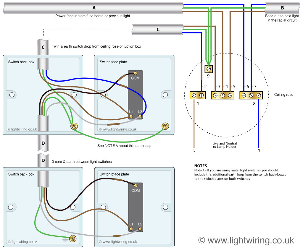
A Wiring Diagram for a 2 Way Switch outlines the circuit connections that enable controlling a single light fixture from two different locations. For instance, in a hallway, a light can be turned on and off at the beginning and end.
These diagrams are crucial for electricians and DIY enthusiasts, ensuring proper installation and functionality. They enhance safety by preventing electrical hazards and provide a visual guide for troubleshooting issues. One notable historical development was the invention of the toggle switch in the 1890s, which simplified the control of electrical circuits and led to the widespread adoption of 2 way switches.
This article will delve deeper into the components, connections, and practical applications of Wiring Diagrams for 2 Way Switches, providing valuable insights for electrical professionals and anyone interested in home electrical systems.
Wiring Diagrams for 2 Way Switches are essential for electrical professionals and DIY enthusiasts alike, providing a visual guide for installing and troubleshooting these circuits. Key aspects to consider include:
- Circuit Design
- Switch Types
- Wire Types
- Safety Precautions
- Testing Procedures
- Code Compliance
- Tools and Materials
- Troubleshooting Techniques
- Practical Applications
- Historical Evolution
Understanding these aspects is crucial for ensuring safe and effective operation of 2 way switch circuits. For instance, proper circuit design minimizes the risk of electrical hazards, while selecting the correct switch type and wire gauge ensures reliable performance. Moreover, adhering to code compliance and safety precautions is paramount to prevent accidents and electrical fires.
Circuit Design
Circuit design is the foundation of any Wiring Diagram for a 2 Way Switch. It involves carefully planning the layout and connections of electrical components to achieve the desired functionality and safety.
-
Switch Configuration
Selecting the right type of switch (e.g., single-pole double-throw, three-way) is crucial for controlling the light fixture from two locations. -
Wire Selection
Choosing the appropriate wire gauge and insulation type ensures safe and reliable current flow throughout the circuit. -
Power Source
Determining the power source (e.g., AC or DC, voltage) and its connection to the circuit is essential for proper operation. -
Grounding
Establishing a proper grounding system protects against electrical shocks and ensures the safe operation of the circuit.
Effective circuit design considers factors such as load capacity, voltage drop, and potential hazards, ensuring the efficient and safe operation of the 2 way switch circuit. By understanding and adhering to these design principles, electricians can create reliable and code-compliant installations.
Switch Types
In the context of Wiring Diagrams for 2 Way Switches, the selection of switch types is a critical component that governs the functionality and control of the lighting circuit. The type of switch used directly influences the wiring diagram and the connections required to achieve the desired switching operation.
Real-life examples of switch types commonly used in 2 way switch circuits include:
- Single-Pole Double-Throw (SPDT) Switches: These switches have two input terminals and two output terminals, allowing them to control a single light fixture from two different locations.
- Three-Way Switches: These switches have three terminals and are specifically designed for 2 way switch circuits. They allow for the control of a single light fixture from three or more locations.
Understanding the relationship between switch types and wiring diagrams is crucial for electricians and DIY enthusiasts. By selecting the appropriate switch type and following the corresponding wiring diagram, they can ensure the proper functionality and safety of 2 way switch circuits. This understanding empowers individuals to troubleshoot and maintain these circuits effectively, enhancing the safety and convenience of electrical systems in residential and commercial buildings.
Wire Types
In the context of Wiring Diagrams for a 2 Way Switch, the selection of appropriate wire types is a crucial aspect that directly impacts the functionality and safety of the electrical circuit. The type of wire used determines its current-carrying capacity, insulation properties, and flexibility, all of which play a critical role in ensuring the proper operation of the circuit.
Real-life examples of wire types commonly used in Wiring Diagrams for a 2 Way Switch include:
- Solid Copper Wire: This type of wire is characterized by its solid core, providing excellent conductivity and durability. It is commonly used for fixed wiring installations, such as in walls and ceilings.
- Stranded Copper Wire: Unlike solid copper wire, stranded copper wire consists of multiple strands of smaller copper wires twisted together. This construction offers greater flexibility, making it suitable for applications where frequent bending or movement is required.
- Romex Cable: Romex cable is a widely used type of non-metallic sheathed cable that combines two or more insulated wires within a single jacket. It is commonly employed in residential and commercial buildings for various electrical applications, including 2 way switch circuits.
Understanding the relationship between wire types and Wiring Diagrams for a 2 Way Switch is essential for electricians and DIY enthusiasts alike. By selecting the appropriate wire type based on the specific requirements of the circuit, they can ensure the safe and reliable operation of the electrical system. This understanding empowers individuals to make informed decisions when installing or maintaining 2 way switch circuits, contributing to the overall safety and functionality of electrical systems.
Safety Precautions
In the context of Wiring Diagrams for a 2 Way Switch, safety precautions play a paramount role in ensuring the safe and reliable operation of the electrical circuit. These precautions encompass a range of measures designed to prevent electrical hazards, protect individuals from injury, and minimize the risk of property damage.
The inclusion of safety precautions in Wiring Diagrams for a 2 Way Switch is not merely a recommendation but a critical component that directly impacts the safety and code compliance of the electrical installation. By adhering to these precautions, electricians and DIY enthusiasts can proactively address potential hazards and ensure the long-term integrity of the circuit.
Real-life examples of safety precautions commonly found in Wiring Diagrams for a 2 Way Switch include proper grounding techniques, the use of insulated wires and terminals, and the inclusion of overcurrent protection devices such as fuses or circuit breakers. These measures work in conjunction to minimize the risk of electrical shocks, short circuits, and fires.
Understanding the practical significance of safety precautions in Wiring Diagrams for a 2 Way Switch empowers individuals to make informed decisions during electrical installations and maintenance procedures. By prioritizing safety and adhering to established guidelines, they can contribute to a safer electrical environment, reducing the likelihood of accidents and ensuring the well-being of individuals and property.
Testing Procedures
Testing procedures are integral to the installation and maintenance of wiring diagrams for 2 way switches. These systematic processes help ensure the safety, reliability, and functionality of the electrical circuit, identifying and rectifying any potential issues before they cause problems.
-
Continuity Test
A continuity test verifies the complete circuit path, ensuring that electricity can flow properly. It involves using a multimeter to check for continuity between different points in the circuit, such as between the switch terminals and the light fixture.
-
Polarity Test
A polarity test determines the correct orientation of the wires, ensuring that the current flows in the intended direction. It involves using a multimeter to check the polarity of the wires, identifying the live and neutral wires.
-
Ground Fault Test
A ground fault test checks for proper grounding, which is essential for safety. It involves using a ground fault tester to verify that the circuit is properly grounded, preventing electrical shocks.
-
Load Test
A load test verifies that the circuit can handle the intended electrical load, ensuring that the wiring and components are adequate. It involves connecting the circuit to the intended load, such as a light fixture or appliance, and monitoring its performance.
By conducting these testing procedures, electricians can ensure that the wiring diagram for a 2 way switch is accurate, safe, and functional. These tests help identify and resolve potential issues, preventing electrical hazards, ensuring reliable operation, and extending the lifespan of the electrical system.
Code Compliance
Code compliance is a fundamental aspect of Wiring Diagrams for a 2 Way Switch, influencing the safety, reliability, and legal compliance of electrical installations. Electrical codes are established sets of regulations and standards that govern the design, installation, and maintenance of electrical systems, ensuring the protection of individuals and property from electrical hazards.
Adhering to code compliance in Wiring Diagrams for a 2 Way Switch involves incorporating specific requirements and guidelines into the design and implementation of the circuit. These requirements typically include proper grounding techniques, the use of appropriate wire gauges and insulation, and the installation of overcurrent protection devices such as fuses or circuit breakers. By following code-compliant practices, electricians can minimize the risk of electrical fires, shocks, and other hazards, ensuring the safety and proper functioning of the electrical system.
Real-life examples of code compliance in Wiring Diagrams for a 2 Way Switch include the use of color-coded wires to distinguish between live, neutral, and ground conductors, the installation of electrical boxes to house switches and connections, and the proper labeling of circuits for easy identification and maintenance. Understanding the practical applications of code compliance empowers individuals to make informed decisions during electrical installations and repairs, contributing to a safer and more reliable electrical environment.
In summary, code compliance is a critical component of Wiring Diagrams for a 2 Way Switch, ensuring the safety and integrity of electrical systems. By adhering to established codes and standards, electricians and DIY enthusiasts can minimize electrical hazards, protect property, and ensure the long-term functionality of electrical installations.
Tools and Materials
In the context of Wiring Diagrams for a 2 Way Switch, tools and materials play a critical role in ensuring the safe and efficient installation, operation, and maintenance of the electrical circuit. These elements encompass various components, each with its unique function and implications for the overall performance of the system.
-
Electrical Wires
Electrical wires are the backbone of any wiring diagram, providing the pathways for current flow. The selection of appropriate wire gauge and insulation type is crucial for ensuring safe and reliable operation of the circuit.
-
Switches
Switches are the control elements of the circuit, allowing users to turn the light fixture on or off from multiple locations. Single-pole double-throw switches and three-way switches are commonly used in 2 way switch circuits.
-
Electrical Boxes
Electrical boxes house the switches and provide a secure enclosure for the electrical connections. They come in various sizes and shapes to accommodate different switch configurations and wiring needs.
-
Tools
Essential tools for working with 2 way switch wiring diagrams include screwdrivers, wire strippers, voltage testers, and pliers. These tools enable electricians and DIY enthusiasts to safely install, troubleshoot, and maintain the circuit.
Understanding the tools and materials involved in Wiring Diagrams for a 2 Way Switch is fundamental for ensuring the proper functioning and safety of the electrical system. By selecting the appropriate components, using the correct tools, and adhering to established electrical codes, individuals can confidently undertake electrical projects, ensuring a reliable and code-compliant installation.
Troubleshooting Techniques
Troubleshooting techniques in the context of Wiring Diagrams for a 2 Way Switch are invaluable for identifying and resolving potential issues, ensuring the proper operation and safety of the circuit. These techniques involve a systematic approach to diagnosing and rectifying faults, preventing inconvenience, electrical hazards, and costly repairs.
-
Identifying Faulty Components
A crucial troubleshooting technique involves identifying faulty components within the circuit. This can include examining switches, wires, and electrical connections for signs of damage, loose connections, or corrosion. Replacing faulty components is essential to restore the circuit’s functionality.
-
Checking Circuit Continuity
Circuit continuity testing is a fundamental troubleshooting technique that verifies the complete electrical pathway. Using a multimeter, electricians can check for continuity between different points in the circuit, ensuring that current can flow freely. This helps identify breaks or interruptions in the circuit.
-
Polarity Verification
For 2 way switch circuits, polarity verification is crucial. Incorrect polarity can prevent the circuit from functioning properly or even pose safety hazards. Using a multimeter, electricians can verify the correct orientation of the wires, ensuring that live and neutral wires are connected accordingly.
-
Load Testing
Load testing involves connecting the circuit to its intended load, such as a light fixture. By observing the circuit’s performance under load, electricians can identify potential issues related to insufficient wire gauge, incorrect switch ratings, or overloading, ensuring the circuit can handle the electrical demand.
Overall, troubleshooting techniques for Wiring Diagrams for a 2 Way Switch empower electricians and DIY enthusiasts with a structured approach to diagnosing and resolving circuit problems. By understanding these techniques and applying them systematically, individuals can ensure the safety, reliability, and optimal performance of their electrical systems.
Practical Applications
Practical applications form the cornerstone of Wiring Diagrams for a 2 Way Switch, translating theoretical concepts into tangible electrical installations that enhance convenience, safety, and energy efficiency in various settings.
-
Residential Lighting Control
In homes, 2 way switch circuits are commonly used to control lighting in hallways, stairwells, and large rooms, providing convenient control from multiple locations, enhancing accessibility and ease of use.
-
Commercial Building Automation
In commercial buildings, 2 way switch circuits are integrated into building automation systems, allowing centralized control of lighting and other electrical systems, optimizing energy consumption and reducing operational costs.
-
Industrial Machinery Control
In industrial settings, 2 way switch circuits are employed to control machinery and equipment from multiple operator stations, enhancing safety and efficiency in hazardous or remote locations.
-
Outdoor Lighting Management
2 way switch circuits extend lighting control outdoors, enabling convenient operation of landscape lighting, security lights, and other outdoor fixtures from both indoor and outdoor locations, enhancing security and ambiance.
These practical applications demonstrate the versatility and widespread use of Wiring Diagrams for a 2 Way Switch, providing a deeper understanding of their real-world implications in various electrical installations.
Historical Evolution
The historical evolution of Wiring Diagrams for a 2 Way Switch mirrors the advancements in electrical engineering and the growing need for convenient and efficient lighting control. This evolution encompasses various aspects, including the development of switch technologies, improvements in wire insulation, and the introduction of safety standards.
-
Early Switch Designs
Early 2 way switches were simple mechanical devices with limited current-carrying capacity. They often lacked proper insulation and safety features, posing potential electrical hazards.
-
Insulation Advancements
The development of insulated wires and cables revolutionized electrical installations. Insulated conductors prevented short circuits and electrical shocks, enhancing the safety and reliability of 2 way switch circuits.
-
Standardization and Safety Codes
As electrical installations became more prevalent, the need for standardization and safety regulations arose. The introduction of electrical codes ensured that 2 way switch circuits were designed and installed according to specific safety standards, minimizing the risk of electrical fires and accidents.
-
Modern Switch Technologies
Modern 2 way switches incorporate advanced technologies such as electronic switching and wireless communication. These switches offer increased functionality, energy efficiency, and remote control capabilities, further enhancing the convenience and versatility of 2 way switch circuits.
The historical evolution of Wiring Diagrams for a 2 Way Switch has been driven by the pursuit of safety, efficiency, and convenience in electrical installations. As technology continues to advance, we can expect further innovations in 2 way switch designs and applications, shaping the future of lighting control systems.


Related Posts


