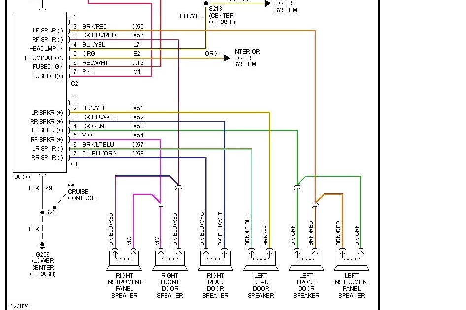
A Radio Wiring Diagram For A 1999 Dodge Ram 1500 provides a detailed visual representation of the electrical connections within the vehicle’s radio system, enabling users to understand and maintain the system. It includes information on wire colors, connector locations, and pinouts.
Understanding these diagrams is essential for troubleshooting radio issues, adding aftermarket components, and ensuring proper functionality. For instance, it helps identify damaged wires, locate connectors, and determine the correct connections for speakers, antennas, and other devices. They serve as a valuable reference tool for both DIY enthusiasts and professional technicians.
The development of standardized radio wiring diagrams industry-wide has significantly simplified vehicle maintenance and repair, allowing individuals with varying technical skills to navigate electrical systems with greater confidence. These diagrams have become an integral part of automotive manuals and repair resources.
Understanding the essential aspects of radio wiring diagrams for a 1999 Dodge Ram 1500 is crucial for maintaining and troubleshooting the vehicle’s audio system. These diagrams provide a comprehensive overview of the electrical connections, enabling users to identify issues, add components, and ensure proper functionality. Let’s explore nine key aspects:
- Wiring Color Codes: Each wire in the system has a specific color code, allowing for easy identification and tracing.
- Connector Types: Diagrams specify the types of connectors used, ensuring proper mating and preventing electrical issues.
- Pinouts: Diagrams clearly indicate the pin configuration of connectors, ensuring correct wire connections.
- Grounding Points: Diagrams show the designated grounding points for the radio system, ensuring proper electrical flow.
- Antenna Connections: Diagrams detail the connections for the radio antenna, ensuring optimal signal reception.
- Speaker Connections: Diagrams provide information on speaker wire connections, ensuring proper sound output.
- Power Connections: Diagrams specify the power connections for the radio, including constant and switched power sources.
- Accessory Connections: Diagrams show connections for accessories such as steering wheel controls or remote amplifiers.
- Troubleshooting Guide: Some diagrams include troubleshooting tips, assisting users in diagnosing and resolving common issues.
These aspects collectively provide a comprehensive understanding of the radio wiring system, enabling users to perform maintenance and repairs with confidence. Access to accurate and detailed wiring diagrams is essential for ensuring the proper functioning and longevity of the vehicle’s audio system.
Wiring Color Codes: Each wire in the system has a specific color code, allowing for easy identification and tracing.
Within a Radio Wiring Diagram for a 1999 Dodge Ram 1500, wire color codes play a critical role in simplifying the identification and tracing of individual wires within the complex electrical system. These standardized color codes provide a visual cue, enabling users to distinguish between various wires, even if they are bundled together in a wiring harness.
The significance of wire color codes becomes evident when troubleshooting electrical issues or installing new components. By referring to the wiring diagram and matching the wire colors, technicians can quickly locate and identify the specific wire they need to work with. This eliminates guesswork and reduces the risk of accidental connections or damage to the electrical system.
For instance, in a 1999 Dodge Ram 1500, the power wire for the radio is typically red, while the ground wire is black. By following the color codes in the wiring diagram, a technician can easily identify these wires and make the appropriate connections, ensuring that the radio receives power and functions correctly.
Overall, the use of wire color codes in Radio Wiring Diagrams for a 1999 Dodge Ram 1500 streamlines the process of electrical system maintenance and repair, making it more accessible and efficient for both professional technicians and DIY enthusiasts.
Connector Types: Diagrams specify the types of connectors used, ensuring proper mating and preventing electrical issues.
In the context of a Radio Wiring Diagram for a 1999 Dodge Ram 1500, connector types play a crucial role in ensuring the proper mating and functioning of electrical connections within the vehicle’s audio system. These diagrams specify the types of connectors used, such as ISO connectors, mini-ISO connectors, or proprietary connectors specific to Dodge vehicles.
Understanding the connector types is critical because it guides users in selecting the correct connectors and making secure connections. Mismatched or improperly connected connectors can lead to electrical issues, such as poor sound quality, intermittent operation, or even damage to the radio or other components.
For example, the 1999 Dodge Ram 1500 radio wiring diagram may indicate that the radio uses a specific type of ISO connector with a 20-pin configuration. This information ensures that users select the correct mating connector when installing an aftermarket radio or repairing the existing wiring harness.
Furthermore, the diagram may provide detailed pinouts for each connector, specifying the purpose of each pin (e.g., power, ground, speaker outputs, antenna input). This information is essential for troubleshooting electrical issues or modifying the system.
Overall, the specification of connector types in Radio Wiring Diagrams for a 1999 Dodge Ram 1500 enables users to make informed decisions about connector selection and ensures the proper functioning of the audio system.
Pinouts: Diagrams clearly indicate the pin configuration of connectors, ensuring correct wire connections.
Within the context of a Radio Wiring Diagram for a 1999 Dodge Ram 1500, pinouts play a critical role in ensuring the proper functioning of the audio system. Pinouts provide a detailed layout of the connectors used in the system, specifying the purpose and arrangement of each pin.
- Wire Identification: Pinouts enable users to identify the specific function of each wire connected to a connector. This information is crucial for troubleshooting electrical issues or modifying the system, as it allows users to trace wires and determine their intended purpose.
- Connector Compatibility: Pinouts ensure that the correct connectors are used when making electrical connections. By matching the pin configuration of the connector to the pinout diagram, users can avoid misconnections and potential damage to the system.
- Signal Routing: Pinouts specify the routing of electrical signals through the connector. This information is essential for understanding how the system is designed and for troubleshooting signal-related issues.
- Power Distribution: In the context of a radio wiring diagram, pinouts indicate the distribution of power to various components. This information is critical for ensuring that the radio and other connected devices receive the appropriate voltage and amperage.
Overall, pinouts are a fundamental aspect of Radio Wiring Diagrams for a 1999 Dodge Ram 1500, providing essential information for understanding, troubleshooting, and modifying the vehicle’s audio system.
Grounding Points: Diagrams show the designated grounding points for the radio system, ensuring proper electrical flow.
Within the context of a Radio Wiring Diagram for a 1999 Dodge Ram 1500, grounding points play a critical role in establishing a proper electrical pathway for the radio system to function correctly. These diagrams clearly indicate the designated grounding points, ensuring that the radio and its components are properly connected to the vehicle’s chassis or other designated grounding locations.
- Chassis Ground: The chassis ground is the primary grounding point for the radio system. It provides a low-resistance path for electrical current to flow from the radio to the vehicle’s metal frame, which acts as a common ground for all electrical components.
- Antenna Ground: The antenna ground is a dedicated grounding point for the radio’s antenna. It ensures that the antenna can receive and transmit signals effectively by providing a stable electrical reference point.
- Speaker Ground: Each speaker in the audio system requires a proper ground connection to complete the electrical circuit and allow sound to be produced. The wiring diagram specifies the grounding points for each speaker, ensuring that they are connected to the vehicle’s chassis or a designated grounding location.
- Power Ground: In some cases, the radio may have a dedicated power ground connection. This connection provides a separate grounding path for the radio’s power supply, ensuring that electrical noise and interference are minimized.
Understanding and correctly connecting the grounding points in a Radio Wiring Diagram for a 1999 Dodge Ram 1500 is essential for ensuring proper electrical flow, minimizing noise and interference, and maintaining the optimal performance of the radio system. Proper grounding also contributes to the overall safety and reliability of the vehicle’s electrical system.
Antenna Connections: Diagrams detail the connections for the radio antenna, ensuring optimal signal reception.
In the comprehensive landscape of a Radio Wiring Diagram for a 1999 Dodge Ram 1500, antenna connections play a significant role in establishing a robust communication link between the vehicle’s audio system and the surrounding environment. These diagrams provide detailed instructions on connecting the radio antenna, which is essential for receiving clear and consistent radio signals.
- Antenna Type: The wiring diagram specifies the type of antenna compatible with the radio system. It may indicate whether the vehicle uses a whip antenna, mast antenna, or other specific antenna design.
- Mounting Location: The diagram provides guidance on the designated mounting location for the antenna. This information ensures proper signal reception and minimizes interference from other electrical components.
- Coaxial Cable: The wiring diagram details the type of coaxial cable required to connect the antenna to the radio. It specifies the cable’s impedance, length, and any necessary adapters or connectors.
- Grounding: Proper grounding of the antenna is crucial for optimal signal reception. The wiring diagram indicates the designated grounding point for the antenna, which is typically connected to the vehicle’s chassis.
Understanding and correctly implementing the antenna connections outlined in the Radio Wiring Diagram for a 1999 Dodge Ram 1500 is essential for maximizing the performance of the vehicle’s radio system. Proper antenna connections ensure strong and reliable signal reception, allowing for clear and enjoyable audio experiences while on the road.
Speaker Connections: Diagrams provide information on speaker wire connections, ensuring proper sound output.
Within the intricate network of a Radio Wiring Diagram for a 1999 Dodge Ram 1500, speaker connections play a fundamental role in translating electrical signals from the radio into audible sound. These diagrams provide detailed instructions on connecting speakers to the radio system, ensuring optimal sound quality and volume.
- Wire Gauge and Type: The wiring diagram specifies the appropriate wire gauge and type for speaker connections. Selecting the correct wire ensures efficient signal transmission and minimizes power loss.
- Polarity: Speaker connections must adhere to proper polarity, ensuring that the positive terminal of the speaker is connected to the positive terminal of the amplifier or radio. Incorrect polarity can result in reduced sound quality and potential damage to the speakers.
- Impedance Matching: The wiring diagram provides guidance on matching the impedance of the speakers to the amplifier or radio. Impedance matching ensures efficient power transfer and optimal sound reproduction.
- Speaker Placement: The diagram may include recommendations for speaker placement within the vehicle to achieve the desired soundstage and listening experience.
Understanding and correctly implementing speaker connections outlined in the Radio Wiring Diagram for a 1999 Dodge Ram 1500 is crucial for achieving a high-quality audio system. Proper speaker connections ensure that the radio can deliver clear and balanced sound, enhancing the overall driving experience.
Power Connections: Diagrams specify the power connections for the radio, including constant and switched power sources.
In the intricate network of a Radio Wiring Diagram for a 1999 Dodge Ram 1500, power connections play a crucial role in ensuring the radio’s functionality and performance. These diagrams provide detailed instructions on connecting the radio to the vehicle’s electrical system, specifying both constant and switched power sources.
- Constant Power: Constant power is supplied to the radio at all times, even when the ignition is turned off. This power maintains the radio’s memory settings, such as presets and clock, and allows features like clock display and anti-theft systems to operate continuously.
- Switched Power: Switched power is supplied to the radio only when the ignition is turned on. This power is used to operate the radio’s main functions, such as audio playback and volume control. When the ignition is turned off, switched power is cut off, turning off the radio.
- Battery Connection: The radio’s constant power connection is typically wired directly to the vehicle’s battery. This ensures that the radio has a reliable power source, even when the engine is not running.
- Fuse Protection: Both constant and switched power connections are protected by fuses to prevent damage to the radio or electrical system in the event of a short circuit or power surge.
Understanding and correctly implementing the power connections outlined in the Radio Wiring Diagram for a 1999 Dodge Ram 1500 is crucial for ensuring that the radio operates as intended. Proper power connections provide a stable and reliable electrical supply, allowing the radio to deliver optimal performance and enhance the overall driving experience.
Accessory Connections: Diagrams show connections for accessories such as steering wheel controls or remote amplifiers.
Within the comprehensive landscape of a Radio Wiring Diagram for a 1999 Dodge Ram 1500, accessory connections hold a significant place, enabling the integration of various additional components and features that enhance the overall audio experience and vehicle functionality.
- Steering Wheel Controls: Many modern vehicles feature steering wheel-mounted controls for audio functions, allowing drivers to conveniently adjust volume, change tracks, or answer calls without taking their hands off the wheel. The wiring diagram provides clear instructions on connecting these controls to the radio, ensuring seamless integration.
- Remote Amplifiers: For enthusiasts seeking a more powerful and immersive audio experience, the wiring diagram includes detailed guidance on connecting external amplifiers to the radio. These amplifiers boost the audio signal, driving more powerful speakers and delivering a richer, more dynamic sound.
- Subwoofers: Subwoofers add depth and impact to the audio system by reproducing low-frequency sounds. The wiring diagram specifies the connections for integrating a subwoofer into the system, ensuring proper signal routing and power supply.
- Bluetooth Connectivity: Bluetooth technology allows for wireless connection of smartphones or other devices to the radio, enabling hands-free calling and audio streaming. The wiring diagram provides instructions for adding a Bluetooth module to the radio, enhancing convenience and safety while driving.
Understanding and correctly implementing the accessory connections outlined in the Radio Wiring Diagram for a 1999 Dodge Ram 1500 empowers vehicle owners to customize their audio systems, enhance functionality, and enjoy a more personalized and immersive listening experience.
Troubleshooting Guide: Some diagrams include troubleshooting tips, assisting users in diagnosing and resolving common issues.
Within the context of a Radio Wiring Diagram for a 1999 Dodge Ram 1500, the inclusion of a troubleshooting guide provides invaluable assistance to users in identifying and resolving common issues that may arise with the vehicle’s audio system.
A troubleshooting guide typically consists of a series of diagnostic steps, each designed to isolate and identify a potential cause of a problem. For instance, if the radio is not producing any sound, the troubleshooting guide may suggest checking the power connections, inspecting the fuse, or verifying that the speakers are properly connected.
By following the troubleshooting steps outlined in the diagram, users can systematically eliminate potential causes and pinpoint the root of the issue. This can save time and effort compared to randomly trying different solutions or consulting multiple sources for guidance.
Furthermore, a troubleshooting guide often includes tips on how to resolve the identified issue. These tips may involve simple adjustments, such as tightening loose connections or replacing a blown fuse, or they may require more advanced troubleshooting techniques.
Overall, the inclusion of a troubleshooting guide in a Radio Wiring Diagram for a 1999 Dodge Ram 1500 empowers users to diagnose and resolve common audio system issues , enhancing their understanding of the system and promoting self-reliance.


Related Posts


