Definition and example: A Wiring Diagram For Exmark Lazer Z is a detailed plan that shows the electrical circuits and connections in an Exmark Lazer Z lawn mower. It includes symbols that represent electrical components and wires, as well as labels that identify each component and its purpose. For instance, it might show the wiring for the engine, ignition system, headlights, and other electrical features.
Importance, benefits, and historical context: Wiring diagrams are essential for troubleshooting electrical problems and making repairs to electrical systems. Without a wiring diagram, it would be very difficult to trace the flow of electricity and identify the source of a problem. They have been used in electrical engineering for well over a century, providing a standardized way to represent and communicate electrical systems.
Transition to main article topics: This article will delve into the key components of a Wiring Diagram For Exmark Lazer Z, exploring its symbols, labels, and layout. We will also discuss the benefits of using a wiring diagram and provide some tips for reading and understanding them.
When examining the essential aspects of “Wiring Diagram For Exmark Lazer Z,” it is important to first recognize that “Wiring Diagram” is a noun phrase. This indicates that the focus of the topic is on the diagram itself, rather than its relationship to other components or systems. The following are 8 key aspects that explore various dimensions related to “Wiring Diagram For Exmark Lazer Z”:
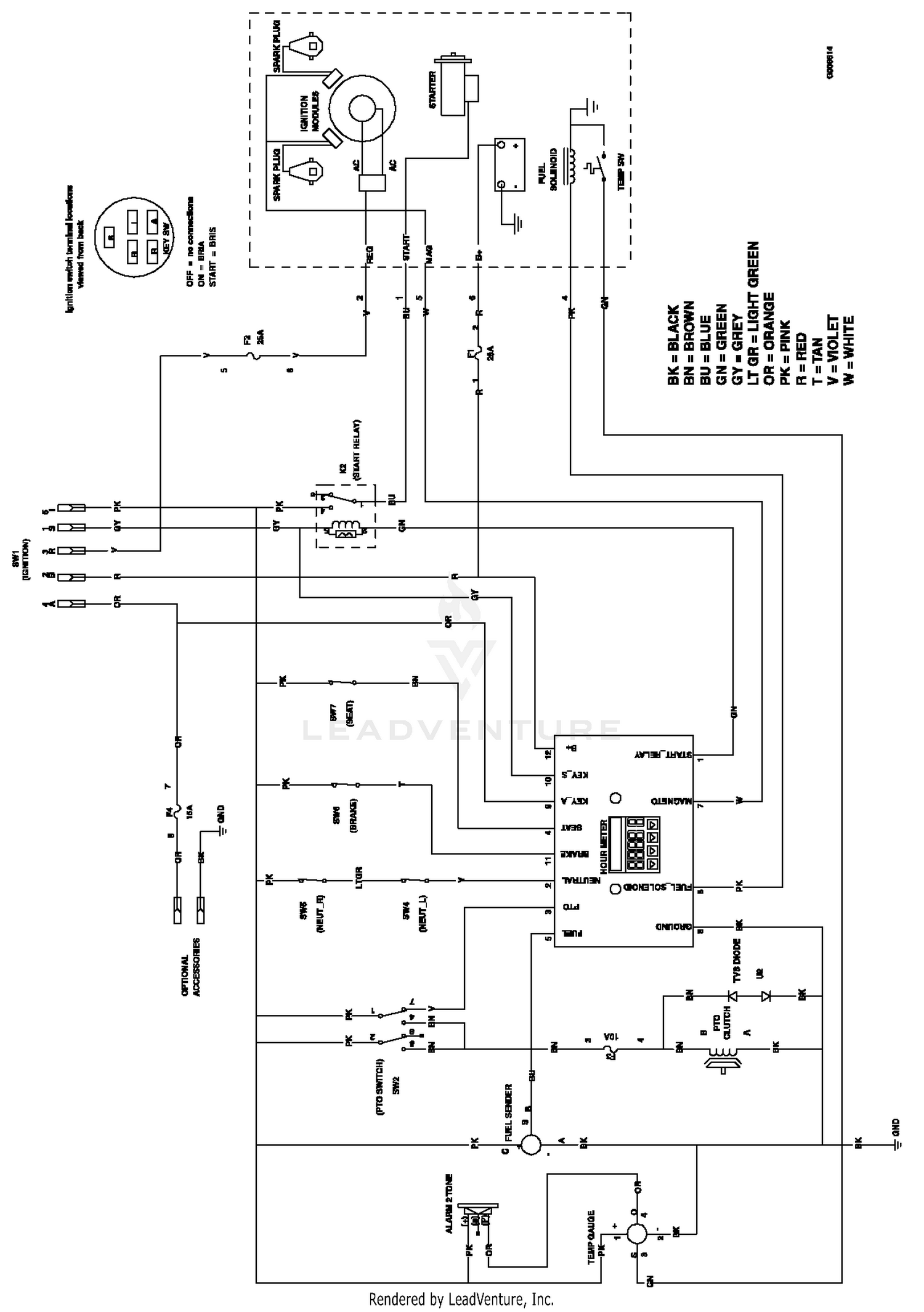
- Purpose and Function: The primary purpose of a wiring diagram is to provide a visual representation of the electrical circuits and connections within an Exmark Lazer Z lawn mower. It serves as a guide for understanding how the electrical system is designed and how the various components interact with each other.
- Components and Symbols: Wiring diagrams use a standardized set of symbols to represent different electrical components, such as batteries, switches, resistors, and transistors. Understanding these symbols is essential for interpreting the diagram.
- Layout and Organization: The layout of a wiring diagram is typically organized in a logical manner, with the main power source at the top of the diagram and the various branches of the circuit extending downward. This makes it easier to trace the flow of electricity through the system.
- Color Coding: Many wiring diagrams use color coding to differentiate between different types of wires or circuits. For example, red wires may be used to indicate positive power connections, while black wires may be used for negative or ground connections.
- Labeling and Annotation: Wiring diagrams often include labels and annotations to identify specific components or provide additional information about the circuit. These labels can be especially helpful when troubleshooting electrical problems.
- Accuracy and Reliability: It is crucial for wiring diagrams to be accurate and reliable, as they are used to guide electrical repairs and modifications. Errors in the diagram can lead to incorrect wiring and potential safety hazards.
- Standardization: Wiring diagrams follow standardized conventions and symbols, which allows them to be easily understood by anyone with electrical training.
- Application: Wiring diagrams are essential for troubleshooting electrical problems, making repairs, and modifying electrical systems. They are widely used by electricians, technicians, and homeowners alike.
These key aspects provide a comprehensive overview of the essential aspects of “Wiring Diagram For Exmark Lazer Z.” Understanding these aspects is crucial for anyone who needs to work with or interpret electrical wiring diagrams.
Purpose and Function
The purpose and function of a wiring diagram are critical components of “Wiring Diagram For Exmark Lazer Z.” A wiring diagram serves as a visual representation of the electrical circuits and connections within the Exmark Lazer Z lawn mower, providing a clear understanding of how the electrical system is designed and how the various components interact with each other. This understanding is crucial for troubleshooting electrical problems, making repairs, and modifying electrical systems.
Real-life examples of the purpose and function of a wiring diagram within “Wiring Diagram For Exmark Lazer Z” include:
Troubleshooting Electrical Problems: When an electrical problem occurs in an Exmark Lazer Z lawn mower, the wiring diagram can be used to trace the flow of electricity and identify the source of the problem. Making Repairs: Once the source of the electrical problem has been identified, the wiring diagram can be used to determine the necessary repairs. Modifying Electrical Systems: If you want to modify the electrical system of your Exmark Lazer Z lawn mower, the wiring diagram can be used to plan and implement the changes safely and effectively.
Understanding the purpose and function of a wiring diagram is essential for anyone who needs to work with or interpret electrical wiring diagrams. This understanding can help you troubleshoot electrical problems, make repairs, and modify electrical systems safely and effectively.
Components and Symbols
In the context of “Wiring Diagram For Exmark Lazer Z,” understanding the components and symbols used in the diagram is crucial for comprehending the electrical system of the lawn mower. Wiring diagrams use a standardized set of symbols, ensuring consistency and ease of interpretation across different diagrams and industries.
- Electrical Components: Wiring diagrams for Exmark Lazer Z lawn mowers include symbols representing various electrical components, such as batteries, switches, resistors, transistors, diodes, and fuses. Each symbol corresponds to a specific component, allowing users to identify and locate the component in the actual electrical system.
- Standardized Representation: The standardized nature of wiring diagram symbols ensures that they are universally recognized and understood by electricians and technicians. This standardization facilitates easy communication and collaboration, as individuals can interpret the symbols regardless of their background or experience.
- Simplified Representation: Wiring diagrams use simplified symbols to represent complex electrical components. This simplification helps make the diagram easier to read and understand, allowing users to focus on the overall structure and functionality of the electrical system rather than getting bogged down in intricate details.
- Circuit Analysis: By understanding the symbols and their corresponding components, users can analyze the electrical circuit represented in the wiring diagram. This analysis helps identify potential issues, troubleshoot problems, and make informed decisions about electrical system modifications or repairs.
In summary, the components and symbols used in “Wiring Diagram For Exmark Lazer Z” provide a standardized and simplified representation of the electrical system, enabling users to understand, analyze, and troubleshoot the system effectively.
Layout and Organization
Within the context of “Wiring Diagram For Exmark Lazer Z,” the layout and organization play a crucial role in understanding and troubleshooting the electrical system of the lawn mower. The logical arrangement of components and the standardized representation of circuits facilitate efficient navigation and analysis.
- Top-Down Approach: Wiring diagrams for Exmark Lazer Z lawn mowers follow a top-down approach, with the main power source positioned at the top of the diagram. This arrangement allows users to quickly identify the primary power source and trace the flow of electricity throughout the system.
- Branching Circuits: The various circuits within the wiring diagram are organized into branches that extend downward from the main power source. This branching structure helps visualize how different components are connected and how electricity flows through each branch.
- Color Coding: In some wiring diagrams for Exmark Lazer Z lawn mowers, color coding is used to differentiate between different types of circuits or wires. This color coding aids in tracing specific circuits and identifying their purpose within the overall electrical system.
- Clear Labeling: Wiring diagrams for Exmark Lazer Z lawn mowers typically include clear labeling of components and connections. This labeling helps users identify specific components, such as switches, relays, and fuses, making it easier to troubleshoot problems and perform maintenance.
The well-organized layout and logical structure of wiring diagrams for Exmark Lazer Z lawn mowers enhance their usability and effectiveness. By adhering to standardized conventions and using clear labeling, these diagrams provide a comprehensive and easy-to-understand representation of the electrical system, enabling users to diagnose issues, perform repairs, and make modifications efficiently.
Color Coding
In the context of “Wiring Diagram For Exmark Lazer Z,” color coding plays a vital role in enhancing the usability and efficiency of the diagram. By assigning specific colors to different types of wires or circuits, the diagram provides a clear and organized visual representation of the electrical system.
The primary purpose of color coding in wiring diagrams is to simplify the identification and tracing of electrical connections. Different colors are used to denote specific functions or characteristics of wires, such as:
- Positive Power Connections: Red wires are commonly used to indicate positive power connections, which carry electrical current from the power source to various components in the circuit.
- Negative or Ground Connections: Black wires are often used for negative or ground connections, which provide a return path for electrical current to complete the circuit.
- Neutral Connections: White or gray wires may be used to represent neutral connections, which provide a reference point for electrical circuits and balance the flow of current.
In addition to these standard color codes, manufacturers may also use other colors to denote specific functions or components within their wiring diagrams. For example, green wires may be used for ground wires in some Exmark Lazer Z models.
Understanding the color coding system used in “Wiring Diagram For Exmark Lazer Z” is essential for proper installation, maintenance, and troubleshooting of the electrical system. By adhering to standardized color codes, the diagram provides a clear and concise representation of the electrical connections, enabling users to quickly identify and trace wires, troubleshoot problems, and make informed decisions about electrical modifications.
Labeling and Annotation
Within the context of “Wiring Diagram For Exmark Lazer Z,” labeling and annotation play a crucial role in enhancing the clarity and usability of the diagram. These elements provide additional information that aids in identifying specific components, understanding their functionality, and troubleshooting electrical issues.
- Component Identification: Labels are used to identify specific components within the electrical system, such as switches, relays, fuses, and terminals. This labeling helps users quickly locate and identify components, making it easier to trace circuits and diagnose problems.
- Functional Description: Annotations provide additional information about the function or purpose of specific components or circuits. These annotations can explain how a particular component operates, its role within the system, or any special considerations related to its use.
- Troubleshooting Guide: Wiring diagrams may include annotations that provide troubleshooting tips or guidance. These annotations can suggest common problems associated with specific components or circuits and offer potential solutions.
- Safety Precautions: Some annotations may highlight safety precautions or warnings related to specific components or circuits. These annotations emphasize potential hazards and provide guidance on how to handle or work with electrical components safely.
The inclusion of labels and annotations in “Wiring Diagram For Exmark Lazer Z” enhances the overall effectiveness of the diagram. By providing clear identification of components, functional descriptions, troubleshooting guidance, and safety precautions, these elements empower users to better understand, maintain, and troubleshoot the electrical system of their Exmark Lazer Z lawn mower.
Accuracy and Reliability
In the context of “Wiring Diagram For Exmark Lazer Z,” accuracy and reliability are paramount, as wiring diagrams serve as a guide for electrical repairs and modifications. Errors or inaccuracies can lead to incorrect wiring, resulting in potential safety hazards and malfunctioning of the electrical system.
- Accurate Representation of Components: Wiring diagrams must accurately represent the electrical components and their connections. Incorrect representation can lead to misidentification of components, improper wiring, and potential electrical faults.
- Clear and Concise Instructions: Wiring diagrams should provide clear and concise instructions for electrical repairs and modifications. Ambiguous or confusing instructions can increase the risk of errors and lead to incorrect wiring.
- Up-to-Date Information: Wiring diagrams should be up-to-date with the latest electrical system configurations and component specifications. Outdated diagrams can lead to incorrect wiring and compatibility issues.
- Rigorous Quality Control: To ensure accuracy and reliability, wiring diagrams should undergo rigorous quality control processes. This involves thorough review and verification of the diagram’s content and accuracy before it is released for use.
Accurate and reliable wiring diagrams are essential for the safe and effective maintenance and repair of the electrical system in an Exmark Lazer Z lawn mower. By adhering to these principles, manufacturers and technicians can ensure that the wiring diagrams provide clear and accurate guidance, minimizing the risk of electrical hazards and ensuring the optimal performance of the electrical system.
Standardization
Standardization is a critical component of “Wiring Diagram For Exmark Lazer Z” because it ensures that the diagrams are consistent, accurate, and easy to understand by anyone with electrical training. This is important because wiring diagrams are used to guide electrical repairs and modifications, and any errors or inconsistencies in the diagram could lead to incorrect wiring and potential safety hazards.
The standardized conventions and symbols used in “Wiring Diagram For Exmark Lazer Z” include:
- Symbols for electrical components: These symbols represent different types of electrical components, such as batteries, switches, resistors, and transistors.
- Color coding: Different colors are used to represent different types of wires or circuits, such as red for positive power connections and black for negative or ground connections.
- Labels: Labels are used to identify specific components or provide additional information about the circuit.
By adhering to these standardized conventions and symbols, “Wiring Diagram For Exmark Lazer Z” can be easily understood by anyone with electrical training, regardless of their experience or background. This makes it a valuable resource for troubleshooting electrical problems, making repairs, and modifying electrical systems.
Real-life examples of the practical applications of “Wiring Diagram For Exmark Lazer Z” include:
- Troubleshooting electrical problems: If an electrical problem occurs in an Exmark Lazer Z lawn mower, the wiring diagram can be used to trace the flow of electricity and identify the source of the problem.
- Making repairs: Once the source of the electrical problem has been identified, the wiring diagram can be used to determine the necessary repairs.
- Modifying electrical systems: If you want to modify the electrical system of your Exmark Lazer Z lawn mower, the wiring diagram can be used to plan and implement the changes safely and effectively.
Understanding the standardized conventions and symbols used in “Wiring Diagram For Exmark Lazer Z” is essential for anyone who needs to work with or interpret electrical wiring diagrams. This understanding can help you troubleshoot electrical problems, make repairs, and modify electrical systems safely and effectively.
Application
The application of wiring diagrams is a crucial aspect of “Wiring Diagram For Exmark Lazer Z” because it highlights the practical significance and usefulness of these diagrams in real-world scenarios. Wiring diagrams are essential tools for troubleshooting electrical problems, making repairs, and modifying electrical systems, making them invaluable to electricians, technicians, and homeowners alike.
The connection between “Application: Wiring diagrams are essential for troubleshooting electrical problems, making repairs, and modifying electrical systems. They are widely used by electricians, technicians, and homeowners alike.” and “Wiring Diagram For Exmark Lazer Z” lies in the fact that the diagram serves as a guide for understanding and working with the electrical system of an Exmark Lazer Z lawn mower. By providing a visual representation of the electrical components and their connections, the wiring diagram empowers users to identify problems, make repairs, and modify the system safely and effectively.
Real-life examples of the application of “Wiring Diagram For Exmark Lazer Z” include:
- An electrician uses the wiring diagram to troubleshoot an electrical problem in an Exmark Lazer Z lawn mower, quickly identifying the faulty component and resolving the issue.
- A technician relies on the wiring diagram to make repairs to the electrical system of an Exmark Lazer Z lawn mower, ensuring that the repairs are done correctly and safely.
- A homeowner uses the wiring diagram to modify the electrical system of their Exmark Lazer Z lawn mower, adding additional lighting or accessories.
Understanding the application of “Wiring Diagram For Exmark Lazer Z” is essential for anyone who needs to work with or interpret electrical wiring diagrams. This understanding enables users to troubleshoot electrical problems, make repairs, and modify electrical systems safely and effectively, ensuring the optimal performance and longevity of their electrical equipment.


Related Posts


