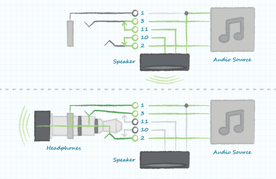
A 3.5 mm audio jack wiring diagram illustrates the electrical connections and physical layout of the terminals within a 3.5 mm audio jack. It specifies the position and function of each terminal, including the ground, left audio channel, and right audio channel. This diagram is crucial for understanding the proper assembly and operation of audio devices that utilize 3.5 mm audio jacks.
The 3.5 mm audio jack is widely used in various electronic devices, such as smartphones, tablets, laptops, and audio players, for connecting headphones, earphones, and external speakers. It enables the transmission of audio signals between devices, facilitating music playback, communication, and audio recording.
Understanding the 3.5 mm audio jack wiring diagram is essential for electronic engineers, audio equipment manufacturers, and hobbyists. It allows for the correct soldering of wires to the terminals, ensuring proper signal transmission and preventing damage to the audio device or connected peripherals.
The 3.5 mm audio jack wiring diagram, a crucial component in understanding the functionality of 3.5 mm audio jacks, encompasses several essential aspects that warrant exploration. These aspects delve into the technical specifications, functional capabilities, and practical applications of this widely used audio connector.
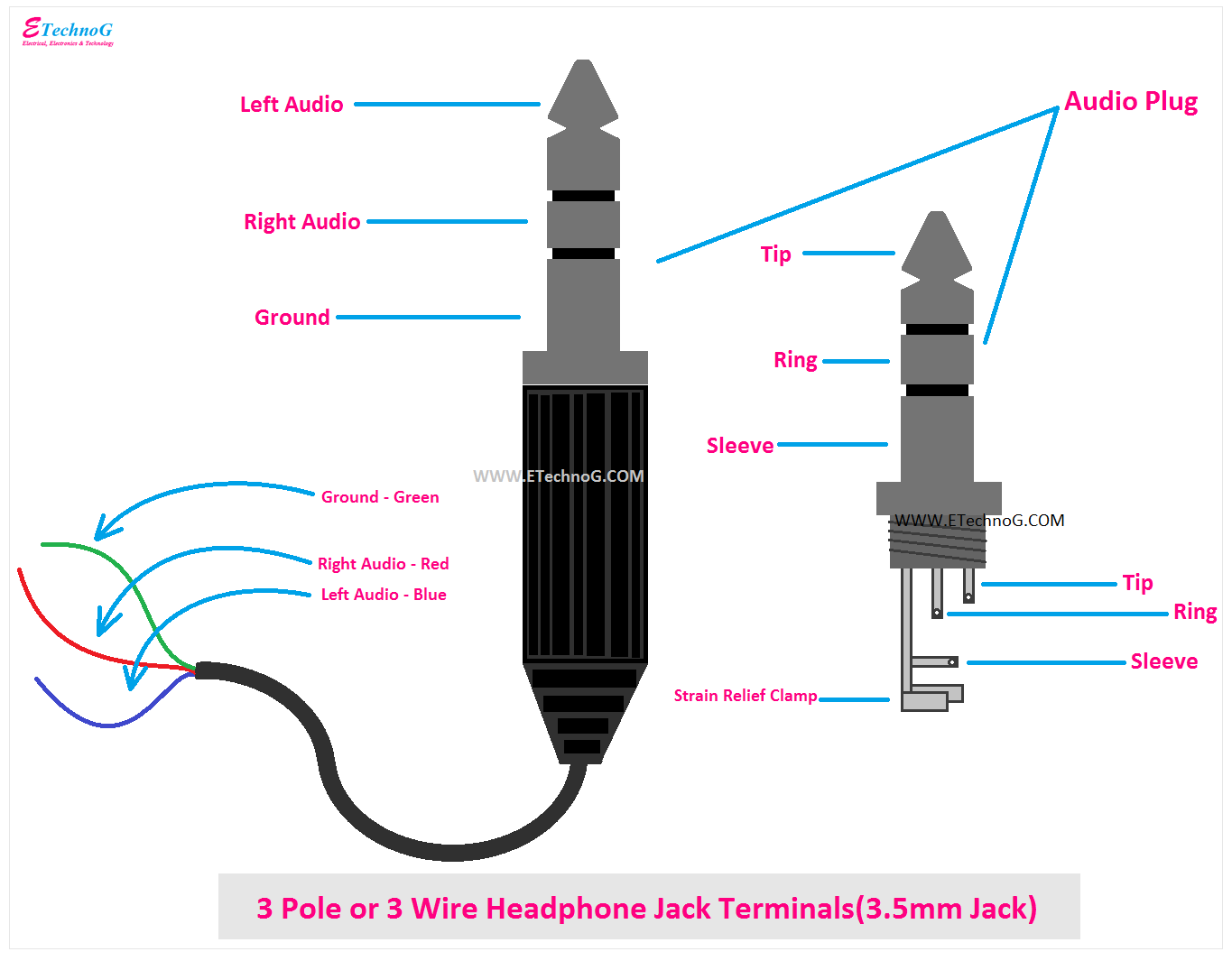
- Terminal Configuration: The diagram outlines the arrangement and labeling of terminals within the jack, including ground, left audio channel, and right audio channel.
- Electrical Connections: It specifies the electrical connections between the terminals, ensuring proper signal flow and preventing short circuits.
- Physical Dimensions: The diagram provides the physical dimensions of the jack, including its diameter, length, and terminal spacing.
- Connector Type: It identifies the specific type of 3.5 mm connector, such as TRS (tip, ring, sleeve) or TRRS (tip, ring, ring, sleeve).
- Compatibility: The diagram indicates the compatibility of the jack with different audio devices and peripherals, such as headphones, earphones, and speakers.
- Signal Transmission: It explains the process of signal transmission through the jack, including the frequency range and impedance.
- Audio Quality: The diagram provides insights into the impact of the jack’s design and construction on the quality of audio transmission.
- Durability: It discusses the durability of the jack, considering factors such as wear and tear, corrosion resistance, and lifespan.
- Troubleshooting: The diagram can assist in troubleshooting audio issues related to the jack, such as loose connections or faulty wiring.
- Industry Standards: It highlights the industry standards and regulations governing the design and manufacturing of 3.5 mm audio jacks.
These aspects collectively provide a comprehensive understanding of the 3.5 mm audio jack wiring diagram, enabling engineers, audio enthusiasts, and users to effectively utilize and maintain audio devices that incorporate this essential connector.
Terminal Configuration
The terminal configuration of a 3.5 mm audio jack wiring diagram is a critical component that defines the physical layout and electrical connections of the jack’s terminals. It establishes the specific arrangement of the ground, left audio channel, and right audio channel terminals within the jack, ensuring proper signal transmission and preventing short circuits.
The diagram provides a clear visual representation of the terminal configuration, allowing engineers, manufacturers, and users to understand the internal structure and functionality of the jack. By adhering to the specified terminal configuration, audio devices can be correctly assembled and connected, facilitating the proper flow of audio signals. Deviations from the standard terminal configuration can result in incorrect wiring, signal interference, or damage to the audio equipment.
Real-life examples of terminal configuration within 3.5 mm audio jack wiring diagrams can be found in various electronic devices, including smartphones, laptops, headphones, and audio players. Each device’s wiring diagram specifies the terminal configuration unique to that particular model, ensuring compatibility with the corresponding audio accessories.
Understanding the terminal configuration is crucial for troubleshooting audio issues related to 3.5 mm audio jacks. By examining the wiring diagram, technicians can identify loose connections, faulty wiring, or terminal damage, enabling them to accurately diagnose and repair the audio device.
In summary, the terminal configuration outlined in a 3.5 mm audio jack wiring diagram is a fundamental aspect that governs the proper functioning of audio devices utilizing this connector. It ensures the correct transmission of audio signals, prevents electrical hazards, and facilitates the compatibility of audio accessories. Understanding the terminal configuration is essential for engineers, manufacturers, and users alike, contributing to the seamless operation and enjoyment of audio devices.
Electrical Connections
The electrical connections specified in a 3.5 mm audio jack wiring diagram are crucial for establishing proper signal flow and preventing short circuits within the audio system. These connections define the electrical pathways between the terminals of the jack, ensuring that audio signals are transmitted efficiently and without interference.
A clear understanding of the electrical connections is essential for engineers and technicians involved in the design, manufacturing, and repair of audio devices. By adhering to the specified electrical connections, they can ensure that audio jacks function optimally, delivering high-quality audio transmission and preventing damage to connected equipment.
Real-life examples of electrical connections within 3.5 mm audio jack wiring diagrams can be found in various electronic devices, including smartphones, laptops, headphones, and audio players. Each device’s wiring diagram specifies the unique electrical connections required for that particular model, ensuring compatibility with the corresponding audio accessories.
Practical applications of understanding electrical connections in 3.5 mm audio jack wiring diagrams extend to troubleshooting and repairing audio issues. By examining the wiring diagram, technicians can identify incorrect wiring, loose connections, or faulty components, enabling them to accurately diagnose and resolve the problem. This understanding contributes to the efficient maintenance and repair of audio devices, ensuring optimal performance and longevity.
In summary, the electrical connections specified in a 3.5 mm audio jack wiring diagram play a critical role in the proper functioning of audio devices. They establish the electrical pathways for signal transmission, prevent short circuits, and ensure compatibility between devices. Understanding these electrical connections is essential for engineers, technicians, and users alike, contributing to the seamless operation and enjoyment of audio devices.
Physical Dimensions
In the context of “3.5 Mm Audio Jack Wiring Diagram”, understanding the physical dimensions of the jack is crucial for ensuring proper fit, compatibility, and optimal performance within audio devices. The diagram provides precise measurements of the jack’s diameter, length, and terminal spacing, enabling manufacturers, engineers, and users to make informed decisions during the design, assembly, and usage of audio equipment.
- Diameter: The diameter of the jack determines its compatibility with the corresponding audio port. A precise fit is necessary to establish a secure connection and prevent signal loss or interference.
- Length: The length of the jack affects its insertion depth into the audio port. Proper insertion ensures optimal electrical contact between the jack’s terminals and the port’s contacts.
- Terminal Spacing: The spacing between the terminals within the jack is critical for maintaining proper electrical connections. Precise terminal spacing prevents short circuits and ensures efficient signal transmission.
Understanding the physical dimensions of a 3.5 mm audio jack wiring diagram extends beyond mere measurements. It involves considering factors such as the type of audio device, the intended use case, and the compatibility with other components within the audio system. By adhering to the specified physical dimensions, engineers can design audio jacks that seamlessly integrate with various devices, ensuring reliable and high-quality audio transmission.
Connector Type
In the context of “3.5 Mm Audio Jack Wiring Diagram”, understanding the connector type is crucial as it defines the physical and functional characteristics of the jack. The diagram specifies the specific type of 3.5 mm connector, such as TRS (tip, ring, sleeve) or TRRS (tip, ring, ring, sleeve), enabling compatibility with the corresponding audio devices and accessories. This aspect plays a pivotal role in ensuring proper signal transmission and preventing damage to equipment.
- Number of Contacts: TRS connectors have three contacts, while TRRS connectors have four. This difference affects the number of audio channels that can be transmitted, with TRS supporting stereo audio and TRRS supporting stereo audio plus microphone input.
- Contact Arrangement: The diagram illustrates the arrangement of the contacts within the connector, ensuring proper alignment with the corresponding contacts in the audio port. This arrangement is critical for maintaining electrical continuity and preventing short circuits.
- Compatibility: The connector type determines the compatibility of the jack with different devices. TRS connectors are commonly used for headphones and earphones, while TRRS connectors are used for devices that require microphone input, such as headsets and smartphones.
- Durability: The diagram may also provide information on the durability of the connector, considering factors such as the materials used and the construction quality. This information is essential for selecting connectors that can withstand repeated insertions and removals, ensuring longevity and reliability.
Understanding the connector type specified in a “3.5 Mm Audio Jack Wiring Diagram” is essential for engineers, manufacturers, and users alike. It ensures that the correct connector is selected for the intended application, preventing compatibility issues and ensuring optimal audio performance.
Compatibility
Within the context of “3.5 Mm Audio Jack Wiring Diagram”, understanding the compatibility of the jack is crucial as it ensures seamless integration with various audio devices and peripherals. The diagram specifies the compatibility of the jack, enabling users to select the appropriate devices and accessories that will function correctly with the jack. This aspect plays a vital role in achieving optimal audio performance and preventing damage to equipment.
The compatibility of a 3.5 mm audio jack is determined by factors such as the connector type, the number of contacts, and the electrical specifications. The diagram provides clear information about these factors, allowing users to make informed decisions when selecting compatible devices. For instance, a TRS connector is commonly used for headphones and earphones, while a TRRS connector is required for devices that require microphone input, such as headsets and smartphones. By adhering to the specified compatibility guidelines, users can avoid compatibility issues and ensure a positive audio experience.
Practical applications of understanding the compatibility of a 3.5 mm audio jack wiring diagram extend to troubleshooting and resolving audio problems. By examining the diagram, users can identify whether a compatibility issue may be causing audio malfunctions. For example, if a user experiences no audio output when connecting headphones to a jack, they can refer to the diagram to verify if the headphones are compatible with the jack’s connector type and electrical specifications. This understanding empowers users to diagnose and resolve compatibility issues, ensuring optimal audio performance from their devices.
In summary, the compatibility information provided in a “3.5 Mm Audio Jack Wiring Diagram” is a critical component for ensuring seamless integration with different audio devices and peripherals. It enables users to make informed decisions when selecting compatible devices, preventing compatibility issues, and resolving audio problems. Understanding the compatibility aspect is essential for maximizing the audio experience and maintaining the longevity of audio equipment.
Signal Transmission
Within the context of “3.5 Mm Audio Jack Wiring Diagram”, understanding signal transmission is crucial as it forms the foundation for effective audio transmission. The diagram explains the process of signal transmission through the jack, including the frequency range and impedance, enabling engineers, manufacturers, and users to design, build, and utilize audio systems that deliver optimal audio quality.
The signal transmission characteristics of a 3.5 mm audio jack are determined by factors such as the jack’s design, the materials used, and the manufacturing process. The wiring diagram provides detailed information about these factors, ensuring that the jack can efficiently transmit audio signals within the specified frequency range and impedance. By adhering to the specified signal transmission parameters, engineers can design audio systems that minimize signal loss, distortion, and interference, resulting in high-fidelity audio reproduction.
Practical applications of understanding signal transmission within a 3.5 mm audio jack wiring diagram extend to troubleshooting and resolving audio problems. By examining the diagram, technicians can identify issues that may be affecting signal transmission, such as loose connections, faulty wiring, or damaged components. Armed with this understanding, they can accurately diagnose and repair the audio system, restoring optimal audio performance.
In summary, the “Signal Transmission” aspect of a 3.5 mm audio jack wiring diagram is a critical component that ensures the efficient and accurate transmission of audio signals. It empowers engineers, manufacturers, and users to design, build, and utilize audio systems that deliver exceptional audio quality. Understanding signal transmission characteristics is essential for maximizing the performance of audio devices and resolving audio issues, contributing to an enhanced audio experience.
Audio Quality
Within the context of “3.5 Mm Audio Jack Wiring Diagram”, understanding audio quality is paramount as it directly influences the user’s listening experience. The diagram provides valuable insights into the impact of the jack’s design and construction on the quality of audio transmission, empowering engineers, manufacturers, and users to make informed decisions and achieve optimal audio performance.
- Contact Materials: The materials used for the jack’s contacts play a crucial role in audio quality. Gold-plated contacts, for instance, exhibit superior conductivity and corrosion resistance, resulting in reduced signal loss and enhanced audio clarity.
- Jack Housing: The material and construction of the jack housing affect its durability and acoustic properties. Metal housings provide better shielding against electromagnetic interference, while plastic housings may introduce noise and distortion.
- Connector Fit: A snug fit between the jack and the mating connector ensures reliable electrical contact and minimizes signal degradation. Loose connections can lead to intermittent audio dropouts and noise.
- Jack Orientation: The orientation of the jack on the device can impact audio quality. Jacks mounted too close to sources of electrical noise, such as power supplies, may introduce hum or interference into the audio signal.
Understanding the factors that influence audio quality in a “3.5 Mm Audio Jack Wiring Diagram” allows engineers to design jacks that deliver pristine audio transmission. Manufacturers can select high-quality materials and construction techniques to ensure that their products meet the demands of audio enthusiasts. Users can make informed choices when selecting audio devices and accessories, knowing that the jack’s design and construction contribute significantly to the overall audio experience.
Durability
Within the context of “3.5 Mm Audio Jack Wiring Diagram”, understanding durability is crucial as it ensures the jack’s longevity and reliability in various operating conditions. The diagram provides insights into the design and construction aspects that contribute to the jack’s durability, enabling engineers, manufacturers, and users to make informed decisions and achieve optimal performance over an extended period.
- Contact Durability: The durability of the jack’s contacts directly impacts the reliability of signal transmission. Gold-plated contacts exhibit superior resistance to wear and tear, maintaining a stable electrical connection over many mating cycles.
- Material Selection: The materials used in the jack’s construction play a significant role in its durability. Metal jacks offer better protection against physical damage and external stresses compared to plastic jacks.
- Environmental Protection: Jacks designed with ingress protection ratings can withstand exposure to dust, moisture, and other environmental factors, ensuring reliable operation in harsh conditions.
- Strain Relief: The strain relief mechanism at the cable entry point prevents excessive bending and stress on the jack’s solder joints, enhancing its durability and preventing cable damage.
Understanding the factors that contribute to durability in a “3.5 Mm Audio Jack Wiring Diagram” empowers engineers to design jacks that can withstand the rigors of everyday use. Manufacturers can select materials and construction techniques that ensure their products meet the durability demands of various applications. Users can make informed choices when selecting audio devices and accessories, knowing that the jack’s durability will contribute to the longevity and reliability of their audio equipment. By considering durability aspects, the “3.5 Mm Audio Jack Wiring Diagram” provides a comprehensive view of the jack’s design and construction, enabling stakeholders to make informed decisions and achieve optimal audio performance throughout the jack’s lifespan.
Troubleshooting
Within the context of “3.5 Mm Audio Jack Wiring Diagram”, understanding troubleshooting techniques is crucial for diagnosing and resolving audio issues related to the jack. The diagram provides valuable insights into the electrical connections and physical layout of the jack, enabling engineers, technicians, and users to effectively identify and fix common audio problems.
- Loose Connections: The wiring diagram helps identify loose connections within the jack or between the jack and the mating connector. By examining the diagram, technicians can verify the correct wiring sequence and ensure that all connections are secure, eliminating intermittent audio dropouts and noise.
- Faulty Wiring: The diagram assists in troubleshooting faulty wiring issues, such as broken wires or incorrect connections. By tracing the signal path through the diagram, technicians can pinpoint the location of the fault and make the necessary repairs, restoring proper audio transmission.
- Contact Oxidation: Over time, the jack’s contacts may oxidize, leading to poor electrical contact and audio degradation. The diagram allows technicians to identify the affected contacts and clean them using appropriate methods, such as contact cleaner or a pencil eraser, to restore optimal audio quality.
- Foreign Objects: Occasionally, foreign objects, such as dust or debris, can get into the jack and interfere with signal transmission. The wiring diagram helps technicians locate the affected area and carefully remove the foreign objects, ensuring proper jack operation.
By understanding the troubleshooting techniques outlined in the “3.5 Mm Audio Jack Wiring Diagram”, engineers, technicians, and users can effectively diagnose and resolve audio issues related to the jack. This knowledge empowers them to maintain optimal audio performance, enhance the user experience, and extend the lifespan of audio devices and accessories.
Industry Standards
The relationship between “Industry Standards” and “3.5 Mm Audio Jack Wiring Diagram” is of paramount importance. Industry standards establish the technical specifications, safety regulations, and quality requirements that govern the design and manufacturing of 3.5 mm audio jacks. These standards ensure interoperability, reliability, and safety across different audio devices and accessories.
As a critical component of the 3.5 Mm Audio Jack Wiring Diagram, industry standards define the electrical connections, pin configurations, and mechanical dimensions of the jack. Adhering to these standards ensures compatibility between audio devices from various manufacturers, preventing mismatches and malfunctions. For instance, the Consumer Electronics Association (CEA) publishes the CEA-930 standard, which outlines the specifications for 3.5 mm audio jacks used in consumer electronics.
Practical applications of understanding industry standards within 3.5 Mm Audio Jack Wiring Diagrams extend to various aspects. Engineers and manufacturers rely on these standards to design and produce audio jacks that meet the required specifications and regulations. Technicians use the diagrams to troubleshoot and repair audio issues related to faulty or damaged jacks, ensuring compliance with industry standards for safety and performance.
In summary, industry standards play a vital role in the design, manufacturing, and maintenance of 3.5 mm audio jacks. The 3.5 Mm Audio Jack Wiring Diagram incorporates these standards to ensure compatibility, reliability, and safety, contributing to the seamless operation of audio devices and enhancing the user experience. Understanding industry standards is essential for engineers, manufacturers, technicians, and users alike, fostering a standardized and interoperable audio ecosystem.


Related Posts


