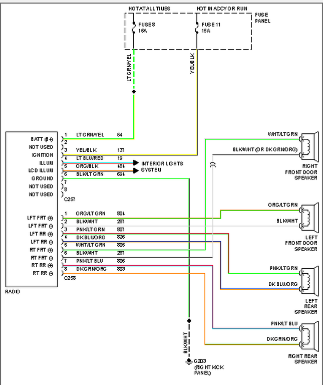
A 2004 Ford F150 Radio Wiring Diagram outlines the electrical connections between the various components of the vehicle’s audio system. It provides a visual representation of the wiring harness, identifying the wires by color, gauge, and function.
This diagram serves as a crucial tool for both troubleshooting and installing an aftermarket radio. By following the wiring diagram, technicians can locate specific wires, diagnose electrical faults, and ensure the proper functioning of the radio system. Its accuracy and detail make it an indispensable resource for ensuring a successful and efficient installation or repair.
The development of standardized wiring diagrams for automotive systems has significantly simplified the tasks of vehicle maintenance and repair. It enables technicians to quickly and easily identify and address electrical issues, rather than relying solely on trial and error. This standardization has contributed to the increased reliability and safety of modern vehicles.
A 2004 Ford F150 Radio Wiring Diagram serves as a vital guide for understanding and manipulating the electrical connections within a vehicle’s audio system. Its multifaceted nature encompasses both noun and adjective characteristics, emphasizing the significance of its components and the role it plays in ensuring the proper functioning of the radio. To fully grasp the essence of this diagram, it is essential to explore its key aspects.
- Accuracy: The diagram provides precise and detailed information, enabling technicians to confidently identify wires and connections.
- Comprehensiveness: It encompasses all the necessary information related to the radio wiring, leaving no room for guesswork or omissions.
- Color-coding: Wires are clearly identified by color, simplifying the process of tracing and connecting them.
- Connector identification: The diagram specifies the type and location of each connector, ensuring proper mating and avoiding confusion.
- Function labeling: Each wire is labeled with its specific function, providing a clear understanding of its purpose within the system.
These aspects, among others, establish the 2004 Ford F150 Radio Wiring Diagram as an indispensable tool for automotive technicians and enthusiasts alike. Its accuracy and comprehensiveness ensure successful installations, repairs, and troubleshooting, ultimately contributing to the optimal performance of the vehicle’s audio system.
Accuracy
In the context of a 2004 Ford F150 Radio Wiring Diagram, accuracy is paramount. It ensures that technicians can confidently identify wires and connections, leading to successful installations, repairs, and troubleshooting. This accuracy manifests in several key facets:
- Comprehensive Details: The diagram provides detailed information on every wire and connection, leaving no room for ambiguity or guesswork. Each wire’s color, gauge, and function are clearly labeled, allowing technicians to easily trace and identify them.
- Precise Labeling: Every wire and connection point is precisely labeled with its specific function. This eliminates confusion and ensures that technicians connect wires accurately, minimizing the risk of short circuits or other electrical faults.
- Color-coded Wires: The diagram utilizes a color-coding scheme to differentiate wires, making it easier for technicians to visually identify and trace them. This color-coding corresponds to industry standards, ensuring consistency and ease of use.
- Verified Connections: The diagram has been thoroughly verified to ensure the accuracy of all connections. This verification process involves cross-checking against multiple sources, including the vehicle’s factory wiring harness and technical documentation.
The accuracy of a 2004 Ford F150 Radio Wiring Diagram is not merely a desirable feature; it is a necessity for ensuring the proper functioning and safety of the vehicle’s audio system. By providing precise and detailed information, the diagram empowers technicians to confidently perform their tasks, ultimately contributing to a positive driving experience.
Comprehensiveness
The comprehensiveness of a 2004 Ford F150 Radio Wiring Diagram is a critical factor that sets it apart from less detailed schematics. This characteristic ensures that the diagram provides all the necessary information technicians need to successfully install, repair, or troubleshoot the vehicle’s audio system. Without comprehensive information, technicians would be left to guesswork and potentially make costly mistakes.
A comprehensive 2004 Ford F150 Radio Wiring Diagram includes:
- All wires and their corresponding colors, gauges, and functions
- The location of every connector and its pinouts
- Detailed instructions on how to connect the radio to the vehicle’s electrical system
- Troubleshooting tips to help technicians diagnose and fix problems
The practical applications of a comprehensive 2004 Ford F150 Radio Wiring Diagram are numerous. For example, technicians can use the diagram to:
- Install an aftermarket radio
- Repair a damaged wire
- Troubleshoot a radio that is not working properly
- Add an amplifier or other audio components to the system
By providing all the necessary information in a clear and concise format, a comprehensive 2004 Ford F150 Radio Wiring Diagram empowers technicians to work efficiently and effectively, saving time and money. It is an essential tool for anyone who works on the electrical system of a 2004 Ford F150.
Color-coding
In the context of a 2004 Ford F150 Radio Wiring Diagram, color-coding plays a critical role in simplifying the process of tracing and connecting wires. This user-friendly feature is not merely an aesthetic choice; it is a deliberate design element that enhances the diagram’s functionality and usability.
Color-coding in a 2004 Ford F150 Radio Wiring Diagram serves several key purposes:
- Visual differentiation: Color-coding allows technicians to easily differentiate between wires, even when they are bundled together in a tight space. This visual distinction minimizes the risk of connecting the wrong wires, which can lead to electrical faults or damage to the audio system.
- Simplified tracing: By following the color-coded wires, technicians can quickly trace the path of electrical signals throughout the system. This is particularly useful when troubleshooting electrical issues or installing new components.
- Error reduction: Color-coding helps to reduce the likelihood of errors during installation or repair. By matching the colors of the wires to the corresponding terminals on the radio and other components, technicians can ensure a secure and reliable connection.
A real-life example of color-coding in a 2004 Ford F150 Radio Wiring Diagram is the use of different colors to identify the wires that connect to the speakers. The diagram will typically use a specific color for the positive wire and a different color for the negative wire. This color-coding makes it easy for technicians to identify which wires to connect to each speaker, ensuring proper sound output.
The practical applications of understanding color-coding in a 2004 Ford F150 Radio Wiring Diagram are numerous. For example, technicians can use this knowledge to:
- Quickly identify and connect wires during radio installation
- Trace electrical signals to troubleshoot problems
- Repair damaged wires without having to completely disassemble the system
- Add new audio components, such as amplifiers or subwoofers, with confidence
Overall, color-coding in a 2004 Ford F150 Radio Wiring Diagram is an essential feature that simplifies the process of tracing and connecting wires. By providing visual differentiation, simplifying tracing, and reducing the likelihood of errors, color-coding empowers technicians to work efficiently and effectively, ultimately ensuring the optimal performance of the vehicle’s audio system.
Connector identification
In the intricate web of electrical connections within a vehicle’s audio system, connectors play a pivotal role in ensuring seamless communication between components. The 2004 Ford F150 Radio Wiring Diagram addresses this complexity by providing precise information on connector types and locations, facilitating proper mating and preventing confusion during installation or repair.
- Connector types: The diagram clearly identifies the different types of connectors used in the radio wiring harness, such as ISO connectors, DIN connectors, and RCA connectors. This knowledge enables technicians to select the appropriate mating connectors and avoid compatibility issues.
- Connector locations: The diagram specifies the exact location of each connector within the vehicle, typically using a combination of written descriptions and visual cues. This information guides technicians in quickly locating the correct connectors, saving time and minimizing the risk of misconnections.
- Pinouts: For more complex connectors, the diagram may also include pinout information, indicating the function of each pin within the connector. This detailed information ensures that wires are connected to the correct terminals, preventing short circuits and other electrical hazards.
- Color-coding: In some cases, the diagram may use color-coding to differentiate between connectors, making it easier for technicians to visually identify and match them. This visual cue further simplifies the installation and repair process.
The importance of connector identification in a 2004 Ford F150 Radio Wiring Diagram cannot be overstated. By providing accurate information on connector types, locations, and pinouts, the diagram empowers technicians to confidently perform electrical work on the vehicle’s audio system. This precision reduces the risk of errors, ensures proper functionality, and ultimately enhances the overall driving experience.
Function labeling
In the context of a 2004 Ford F150 Radio Wiring Diagram, function labeling plays a critical role in simplifying the installation, maintenance, and repair of the vehicle’s audio system. By clearly indicating the purpose of each wire, the diagram empowers technicians to make informed decisions and avoid costly mistakes.
The function labeling in a 2004 Ford F150 Radio Wiring Diagram is achieved through the use of standardized color-coding and text annotations. Each wire is assigned a specific color and label that corresponds to its function within the system. For example, the wire responsible for transmitting the audio signal from the radio to the speakers may be labeled “Audio Output” and colored red.
The importance of function labeling cannot be overstated. It enables technicians to quickly identify and connect wires, reducing the risk of errors and ensuring the proper functioning of the audio system. Without function labeling, technicians would be forced to rely on trial and error, which could lead to incorrect connections, electrical faults, or even damage to the radio or other components.
A real-life example of the practical application of function labeling in a 2004 Ford F150 Radio Wiring Diagram is the installation of an aftermarket amplifier. The diagram will typically provide clear instructions on which wires to connect to the amplifier’s input and output terminals. By following the function labeling, the technician can ensure that the amplifier is correctly connected and will function properly.
Overall, the function labeling in a 2004 Ford F150 Radio Wiring Diagram is an essential element that contributes to the efficient and accurate installation, maintenance, and repair of the vehicle’s audio system. It provides technicians with a clear understanding of the purpose of each wire, enabling them to work confidently and effectively.


Related Posts


