A 1 Way Light Switch Wiring Diagram illustrates the electrical connections required to operate a single light fixture with a single switch. It typically includes the switch, light fixture, power source, neutral wire, and ground wire. A simple example is a bedroom where a switch by the door controls a light at the ceiling.
These diagrams are crucial for electrical professionals and DIY enthusiasts alike, ensuring safe and functional lighting systems. They help identify wire connections, switch placements, and proper grounding, preventing potential electrical hazards. A significant historical development is the introduction of insulated wires and polarized plugs, enhancing safety and reducing electrical accidents.
In this article, we will delve deeper into the components, wiring techniques, and safety considerations of 1 Way Light Switch Wiring Diagrams. By understanding these diagrams, readers can gain practical knowledge for electrical projects and contribute to the safe and efficient operation of lighting systems.
Understanding the essential aspects of 1 Way Light Switch Wiring Diagrams is paramount for electrical professionals and DIY enthusiasts alike. These diagrams serve as blueprints, guiding the safe and functional installation of lighting systems. Here are 10 key aspects to consider:
- Power Source
- Switch Type
- Wire Gauge
- Circuit Breaker
- Light Fixture
- Neutral Wire
- Ground Wire
- Electrical Box
- Insulation
- Safety Standards
These aspects are interconnected, ensuring the proper functioning and safety of lighting systems. For instance, selecting the correct wire gauge is crucial to prevent overheating, while proper insulation safeguards against electrical shock. Understanding these aspects enables individuals to make informed decisions, troubleshoot issues, and maintain lighting systems effectively.
Power Source
In the context of 1 Way Light Switch Wiring Diagrams, the power source holds paramount importance, acting as the driving force behind the entire electrical circuit. Without a reliable power source, the switch and light fixture remain inoperable. The power source provides the necessary voltage and current to energize the circuit, enabling the switch to control the flow of electricity to the light fixture.
In most residential and commercial applications, the power source for a 1 Way Light Switch Wiring Diagram is derived from the electrical panel, which distributes electricity throughout the building. The power source typically consists of two wires: a “hot” wire carrying the live current and a “neutral” wire providing a path back to the electrical panel. These wires are connected to the switch and light fixture, completing the circuit.
Understanding the connection between the power source and 1 Way Light Switch Wiring Diagrams is essential for several reasons. Firstly, it helps electricians and DIY enthusiasts identify the correct power source and ensure proper electrical connections. Secondly, it enables troubleshooting and repair of lighting systems by isolating issues related to the power source. Thirdly, it promotes safety by emphasizing the importance of using appropriate gauge wires and circuit breakers to prevent overloading and potential electrical hazards.
Switch Type
Within the context of 1 Way Light Switch Wiring Diagrams, the switch type plays a crucial role in controlling the flow of electricity to the light fixture. Different switch types offer unique functionalities, appearances, and wiring configurations, catering to various application needs. Understanding the different switch types is essential for selecting the most appropriate switch for a particular lighting system.
-
Single-Pole Switch
The most common type of switch used in 1 Way Light Switch Wiring Diagrams, single-pole switches have two terminals for connecting the power source and light fixture. They allow for simple on/off control of a single light fixture.
-
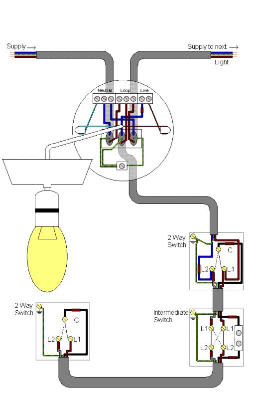
Three-Way Switch
Three-way switches are commonly employed for controlling a single light fixture from two different locations. They have three terminals, enabling switching from either location. Wiring three-way switches requires additional traveler wires between the switch locations.
-
Dimmer Switch
Dimmer switches provide the ability to adjust the brightness of a light fixture. They incorporate variable resistors to regulate the amount of electricity flowing to the light fixture, allowing for customized lighting levels.
-
Smart Switch
Smart switches offer advanced features such as remote control, scheduling, and integration with home automation systems. They connect to Wi-Fi or Bluetooth networks, enabling control via smartphones or voice assistants.
The choice of switch type ultimately depends on the specific requirements of the lighting system. Factors such as the number of light fixtures, desired control points, and desired functionality influence the selection process. By understanding the different switch types available, electricians and DIY enthusiasts can make informed decisions, ensuring optimal performance and user satisfaction.
Wire Gauge
In the context of 1 Way Light Switch Wiring Diagrams, wire gauge is a crucial aspect that determines the thickness and current-carrying capacity of the electrical wires used. Selecting the appropriate wire gauge is essential for ensuring the safe and efficient operation of the lighting system.
-
Conductor Size
The conductor size, measured in American Wire Gauge (AWG), indicates the cross-sectional area of the wire’s conductive material, typically copper or aluminum. Larger conductor sizes have lower resistance, allowing them to carry more current.
-
Current Rating
The current rating of a wire specifies the maximum amount of current it can safely carry without overheating. Exceeding the current rating can lead to insulation damage, wire melting, and potential fire hazards.
-
Voltage Drop
Voltage drop refers to the reduction in voltage along the length of a wire due to its resistance. Using a wire with too small a gauge can result in excessive voltage drop, leading to dimmer lights or malfunctioning devices.
-
Insulation Thickness
The thickness of the wire’s insulation affects its resistance to electrical shock and short circuits. Thicker insulation provides better protection but can also increase the overall diameter of the wire.
Selecting the appropriate wire gauge for a 1 Way Light Switch Wiring Diagram requires considering the length of the wire run, the current draw of the light fixture, and the voltage drop limitations. By adhering to recommended wire gauge standards and using high-quality materials, electricians and DIY enthusiasts can ensure the reliability and safety of their lighting systems.
Circuit Breaker
Within the context of 1 Way Light Switch Wiring Diagrams, a circuit breaker plays a crucial role in protecting the electrical system from overcurrent and short circuits. It acts as an automatic switch, designed to interrupt the flow of electricity when an unsafe condition arises, safeguarding the wiring, light fixture, and other components from potential damage.
-
Tripping Mechanism
This is the core component of a circuit breaker, responsible for detecting excessive current and triggering the interruption mechanism. It consists of a bimetallic strip or magnetic coil that responds to overcurrent conditions, causing the circuit breaker to trip.
-
Amperage Rating
Each circuit breaker has a specific amperage rating, which corresponds to the maximum amount of current it can safely handle. Choosing the correct amperage rating is crucial to ensure that the circuit breaker trips at the appropriate level, preventing damage to the electrical system.
-
Resettable vs. Replaceable
Circuit breakers can be either resettable or replaceable. Resettable circuit breakers can be manually switched back on after tripping, while replaceable circuit breakers require the replacement of the entire unit.
-
Location and Accessibility
Circuit breakers are typically installed in an electrical panel, which is easily accessible for resetting or replacement. They are often grouped together, allowing for quick identification and troubleshooting.
Understanding the role and components of circuit breakers is essential for the safe installation and maintenance of 1 Way Light Switch Wiring Diagrams. By selecting the appropriate amperage rating and ensuring proper installation, electricians and DIY enthusiasts can protect their lighting systems from overcurrent conditions, minimizing the risk of electrical fires and damage.
Light Fixture
Within the context of 1 Way Light Switch Wiring Diagrams, the light fixture serves as the primary component responsible for producing illumination. Understanding the different aspects of light fixtures is crucial for selecting the most suitable fixture for a particular application and ensuring proper wiring and installation.
-
Fixture Type
Light fixtures come in a wide range of types, including recessed lighting, chandeliers, pendant lights, and wall sconces. Each type offers unique aesthetic and functional characteristics, influencing the overall design and ambiance of a space.
-
Bulb Compatibility
Light fixtures are designed to accommodate specific bulb types, such as incandescent, fluorescent, LED, or halogen bulbs. The choice of bulb type depends on factors like energy efficiency, light output, and color temperature.
-
Wiring Configuration
Light fixtures require proper wiring to function correctly. The wiring configuration varies depending on the fixture type and the number of bulbs used. Understanding the wiring diagram is essential for ensuring a safe and functional installation.
-
Mounting Considerations
Light fixtures have different mounting requirements based on their size, weight, and intended location. Proper mounting ensures the fixture is securely installed and meets safety standards.
By considering these aspects of light fixtures, electricians and DIY enthusiasts can make informed decisions when selecting and installing fixtures as part of 1 Way Light Switch Wiring Diagrams. Understanding the compatibility, wiring requirements, and mounting considerations for different light fixtures empowers individuals to create effective and aesthetically pleasing lighting systems.
Neutral Wire
In the context of 1 Way Light Switch Wiring Diagrams, the neutral wire plays a crucial role in completing the electrical circuit and providing a safe and functional lighting system. It serves as the return path for the current, allowing electricity to flow back to the power source.
-
Definition
The neutral wire is a current-carrying conductor that is typically white or gray in color. It is connected to the neutral terminal of the power source and to the neutral terminal of the light fixture.
Understanding the neutral wire and its proper installation is essential for ensuring the safety and functionality of 1 Way Light Switch Wiring Diagrams. By adhering to established electrical codes and using high-quality materials, electricians and DIY enthusiasts can create reliable and efficient lighting systems.
Ground Wire
Within the context of 1 Way Light Switch Wiring Diagrams, the ground wire serves as a crucial safety feature, providing a dedicated path for fault currents to flow back to the power source. It plays a vital role in preventing electrical shocks and ensuring the proper operation of the lighting system.
-
Purpose
The primary purpose of the ground wire is to provide a safe and low-resistance path for any stray electrical currents or fault currents to return to the power source. This helps prevent these currents from flowing through unintended paths, such as the electrical system or the human body.
-
Identification
Ground wires are typically identified by their green or bare copper color. This distinct color coding helps electricians and DIY enthusiasts easily identify and connect the ground wire correctly.
-
Connection
In 1 Way Light Switch Wiring Diagrams, the ground wire is connected to the ground terminal of the power source, the ground terminal of the light fixture, and any metal junction boxes or electrical enclosures. This ensures a continuous path for fault currents to flow back to the power source.
-
Safety
The ground wire plays a critical role in enhancing the safety of the lighting system. By providing a dedicated path for fault currents, it helps prevent electrical shocks, reduces the risk of electrical fires, and ensures the proper operation of circuit breakers and other protective devices.
Understanding the importance and proper installation of the ground wire is essential for creating safe and reliable 1 Way Light Switch Wiring Diagrams. Electricians and DIY enthusiasts must adhere to established electrical codes and use high-quality materials to ensure the safety and functionality of their lighting systems.
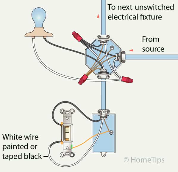
Electrical Box
Within the context of 1 Way Light Switch Wiring Diagrams, an electrical box serves as a crucial component, providing a safe and organized enclosure for electrical connections and components. Its presence is essential for ensuring the proper functioning and safety of the lighting system.
Electrical boxes are typically made of metal or plastic and come in various shapes and sizes to accommodate different wiring configurations and switch types. They provide a secure mounting surface for switches, receptacles, and other electrical devices, ensuring a stable and reliable connection.
In a 1 Way Light Switch Wiring Diagram, the electrical box houses the switch and provides a junction point for the wires connecting the power source, light fixture, and switch. The box protects these connections from physical damage, moisture, and accidental contact, preventing electrical hazards such as short circuits and fires.
Understanding the importance of electrical boxes in 1 Way Light Switch Wiring Diagrams is crucial for both electrical professionals and DIY enthusiasts. Proper installation and maintenance of electrical boxes help ensure the longevity, safety, and code compliance of lighting systems in residential, commercial, and industrial settings.
Insulation
Insulation plays a crucial role in the safety and functionality of 1 Way Light Switch Wiring Diagrams, safeguarding electrical systems and preventing potential hazards. Its primary purpose is to prevent the flow of electricity outside the intended conductive paths, ensuring the safe operation of electrical components and protecting users from electrical shocks.
-
Wire Insulation
Individual electrical wires are coated with non-conductive insulation, typically made of materials like PVC or rubber. This insulation prevents current leakage and short circuits, ensuring that electricity flows only through the intended paths.
-
Switch Insulation
Switches are enclosed in insulated casings to prevent accidental contact with live electrical parts. This insulation safeguards users from electrical shocks and ensures the safe operation of the switch.
-
Electrical Box Insulation
Electrical boxes are often lined with insulating material to protect wires and connections from moisture, dust, and physical damage. This insulation helps prevent electrical faults and ensures the longevity of the wiring system.
-
Ground Insulation
The ground wire, which provides a safety path for fault currents, is also insulated to prevent accidental contact and ensure proper grounding. This insulation helps protect against electrical shocks and ensures the effectiveness of the grounding system.
Proper insulation is essential for the safe and reliable operation of 1 Way Light Switch Wiring Diagrams. By understanding the importance and proper installation of insulation, electricians and DIY enthusiasts can ensure the safety and longevity of their lighting systems.
Safety Standards
Within the context of 1 Way Light Switch Wiring Diagrams, safety standards play a paramount role in ensuring the safe and reliable operation of lighting systems. These standards provide a framework for electrical installations, outlining specific requirements and guidelines to minimize the risk of electrical hazards, fires, and injuries.
Adherence to safety standards is a critical component of 1 Way Light Switch Wiring Diagrams. By following established codes and regulations, electricians can create lighting systems that meet or exceed industry best practices. These standards cover various aspects of electrical installations, including wire selection, circuit protection, grounding, and proper insulation techniques.
Real-life examples of safety standards in 1 Way Light Switch Wiring Diagrams include the use of color-coded wires for easy identification, proper sizing of circuit breakers to prevent overcurrent conditions, and the inclusion of ground wires to provide a safe path for fault currents. Understanding and applying these standards help ensure that wiring diagrams are not only functional but also safe for use in residential, commercial, and industrial settings.
The practical applications of this understanding extend to the prevention of electrical accidents, fires, and injuries. By incorporating safety standards into 1 Way Light Switch Wiring Diagrams, electricians and DIY enthusiasts can contribute to the safe and efficient operation of lighting systems, reducing the risk of potential hazards and ensuring the well-being of building occupants.


Related Posts


