A wiring diagram for a doorbell is a schematic representation that shows the electrical connections between the doorbell button, the bell, and the power source. It provides a visual guide for installing, repairing, or troubleshooting the doorbell system.
Doorbell wiring diagrams are essential for ensuring the proper functioning of the system. They help electricians and homeowners understand the electrical circuitry, identify potential problems, and make necessary repairs or modifications. Additionally, these diagrams can help prevent electrical hazards by guiding the installation process and ensuring that all connections are made safely.
Historically, doorbell wiring diagrams have evolved with the advancement of electrical technologies. In the past, simple diagrams were used for basic doorbell systems. Today, more complex diagrams are necessary for systems that incorporate multiple bells, chimes, and smart features.
Wiring diagrams for doorbells are crucial for understanding the electrical circuitry and ensuring the proper functioning of the system. Various aspects of these diagrams are essential to consider during the content creation process.
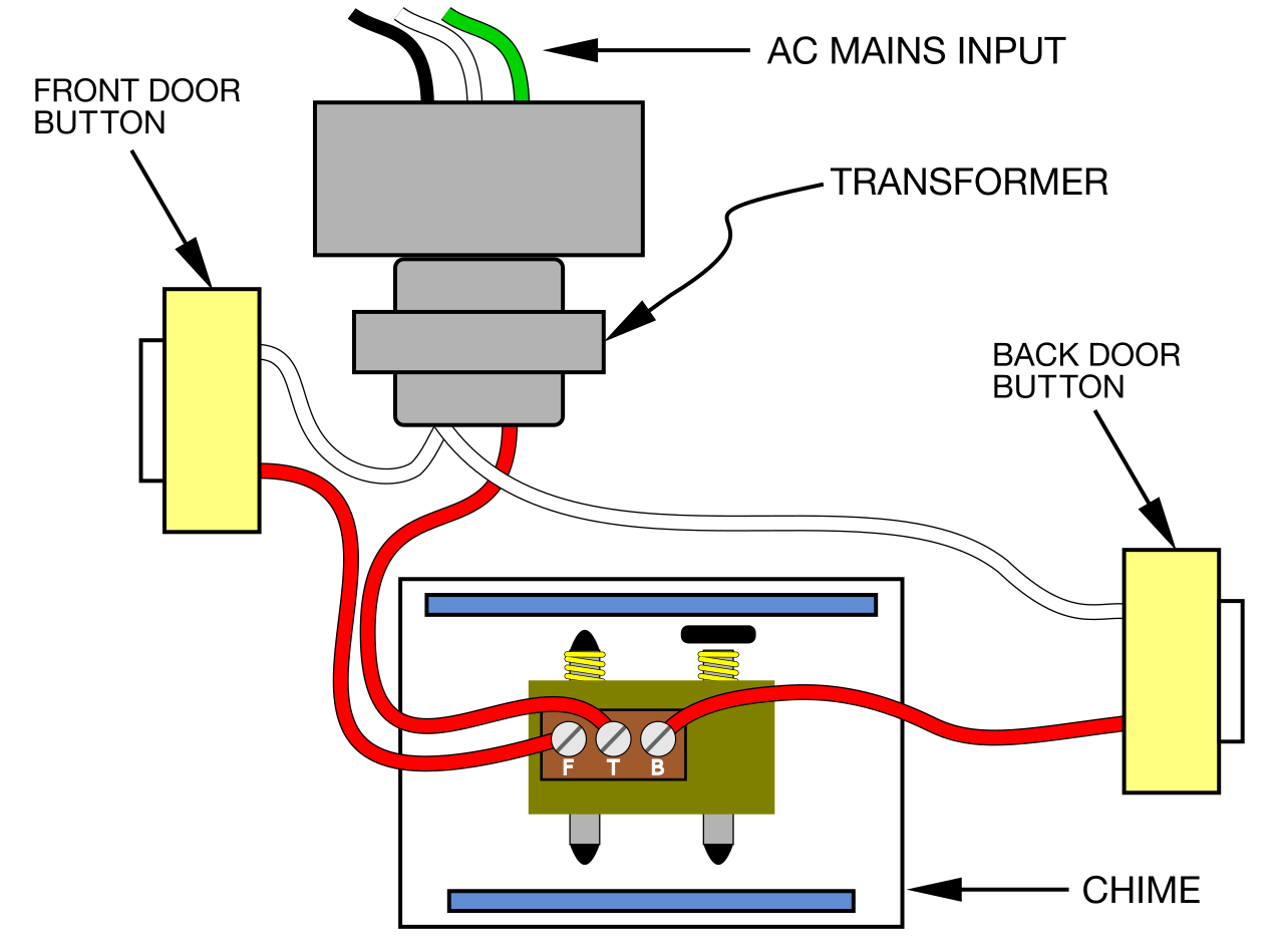
- Components: Doorbell wiring diagrams depict the electrical components involved, including the doorbell button, bell, transformer, and power source.
- Connections: They illustrate the electrical connections between the components, showing how the current flows through the system.
- Wire Types: Diagrams specify the type of wire used for each connection, such as doorbell wire or low-voltage wire.
- Circuit Layout: They provide a visual representation of the circuit layout, including the placement of components and the routing of wires.
- Voltage Requirements: Diagrams indicate the voltage requirements for the doorbell system, typically 12-24 volts.
- Safety Precautions: They highlight safety precautions to follow during installation, such as turning off the power before working on the system.
- Troubleshooting: Diagrams aid in troubleshooting common doorbell problems, such as identifying faulty connections or a blown transformer.
- Codes and Standards: They ensure compliance with electrical codes and standards, promoting safe and reliable installations.
- Customization: Diagrams allow for customization of doorbell systems, such as adding multiple bells or chimes, or integrating smart features.
- Documentation: They serve as documentation for future reference, maintenance, or repairs.
These aspects provide a comprehensive understanding of wiring diagrams for doorbells. They are essential for ensuring the safety, functionality, and reliability of the system. By considering these aspects during content creation, you can provide valuable information to readers who are installing, repairing, or troubleshooting their doorbell systems.
Components
Understanding the components of a doorbell wiring diagram is crucial for comprehending the system’s functionality and ensuring its proper installation and maintenance. These diagrams depict the electrical components involved, including the doorbell button, bell, transformer, and power source, providing a visual representation of their connections and relationships.
- Doorbell Button: The doorbell button initiates the doorbell system by closing an electrical circuit when pressed. It is typically mounted outside the door or near the entrance.
- Doorbell: The doorbell is the sound-emitting component that produces the audible signal when the button is pressed. It can be a chime, buzzer, or a melody player.
- Transformer: The transformer converts the household voltage (typically 120 volts) to a lower voltage (usually 12-24 volts) required by the doorbell system.
- Power Source: The power source provides the electrical energy to operate the doorbell system. It can be a battery or a connection to the home’s electrical wiring.
These components work together to create a functional doorbell system. When the doorbell button is pressed, the circuit is closed, allowing current to flow from the power source through the transformer, doorbell, and back to the power source. This flow of current triggers the doorbell to produce sound, alerting the occupants of the doorbell press.
Connections
In a wiring diagram for a doorbell, the connections between the components play a critical role in determining the system’s functionality and safety. These connections illustrate how the electrical current flows through the system, ensuring that the doorbell button, bell, transformer, and power source work together seamlessly.
Without proper connections, the doorbell system will not function correctly. For instance, if the connection between the doorbell button and the transformer is faulty, the doorbell may not ring when the button is pressed. Similarly, if the connection between the transformer and the bell is loose, the bell may produce a faint or distorted sound.
Understanding the connections in a wiring diagram for a doorbell is essential for several reasons:
- Installation: Proper connections are crucial for a safe and functional doorbell installation. By following the diagram, electricians and homeowners can ensure that all components are connected correctly, reducing the risk of electrical hazards.
- Troubleshooting: Wiring diagrams aid in troubleshooting common doorbell problems. By analyzing the connections, electricians can quickly identify and fix issues such as loose wires, blown transformers, or faulty buttons.
- Customization: Wiring diagrams allow for customization of doorbell systems. For example, if a homeowner wants to add a second bell or chime, they can refer to the diagram to determine the necessary connections.
- Safety: Correct connections ensure the safe operation of the doorbell system. By following the diagram, electricians can avoid potential electrical hazards, such as short circuits and electrical fires.
In conclusion, the connections in a wiring diagram for a doorbell are vital for understanding the system’s functionality, ensuring proper installation, facilitating troubleshooting, enabling customization, and promoting safety. By comprehending the connections and their importance, homeowners and electricians can maintain and repair doorbell systems effectively.
Wire Types
In wiring diagrams for doorbells, specifying the type of wire used for each connection is crucial for ensuring the system’s safety, functionality, and longevity. Doorbell wire and low-voltage wire are the two primary types of wire used in doorbell systems, each with its own characteristics and applications.
Doorbell wire is a stranded, insulated wire specifically designed for doorbell systems. It is typically 18 or 20 gauge and has a voltage rating of 12-24 volts. Doorbell wire is durable, flexible, and resistant to moisture, making it suitable for both indoor and outdoor use. It is commonly used to connect the doorbell button to the transformer and the transformer to the doorbell.
Low-voltage wire is a general-purpose wire that can be used for various low-voltage applications, including doorbell systems. It is typically 18 or 22 gauge and has a voltage rating of 12-24 volts. Low-voltage wire is less expensive than doorbell wire but may not be as durable or moisture-resistant. It is often used for short runs or in areas where durability is not a major concern.
Using the correct type of wire for each connection is essential for the proper functioning of the doorbell system. Doorbell wire should be used for the connections between the doorbell button, transformer, and doorbell. Low-voltage wire can be used for other connections, such as between the transformer and a chime or between multiple doorbells.
By specifying the type of wire used for each connection, wiring diagrams for doorbells provide clear instructions for installation and maintenance. This helps ensure that the system is safe, reliable, and meets the specific requirements of the application.
Circuit Layout
In the context of wiring diagrams for doorbells, the circuit layout plays a vital role in ensuring the system’s proper functioning and safety. A clear visual representation of the circuit layout, including the placement of components and the routing of wires, allows for efficient installation, maintenance, and troubleshooting.
The circuit layout determines the path of electrical current flow within the doorbell system. It specifies the connections between the doorbell button, transformer, doorbell, and power source. A well-designed circuit layout minimizes electrical resistance and ensures that the doorbell operates reliably.
Real-life examples of circuit layout in wiring diagrams for doorbells include:
- Parallel Circuit: In this layout, the doorbell button and doorbell are connected in parallel to the transformer and power source. This allows either component to be replaced or repaired without affecting the other.
- Series Circuit: In this layout, the doorbell button, transformer, and doorbell are connected in series to the power source. A fault in any component will disrupt the entire circuit, requiring careful troubleshooting to identify the issue.
Understanding the circuit layout is crucial for practical applications, such as:
- Installation: Electricians use the circuit layout to determine the placement of components and the routing of wires during installation.
- Troubleshooting: When a doorbell system malfunctions, the circuit layout helps electricians and homeowners identify the faulty component and repair the issue.
- Customization: If a homeowner wants to add a chime or additional doorbell, the circuit layout provides guidance on how to incorporate these components into the existing system.
In conclusion, the circuit layout in a wiring diagram for a doorbell is a critical component that guides the installation, maintenance, and troubleshooting of the system. By providing a visual representation of the electrical connections and component placement, circuit layouts ensure the safe and efficient operation of doorbell systems.
Voltage Requirements
In the context of “Wiring Diagrams for Doorbells,” voltage requirements play a crucial role in ensuring the system’s safe and efficient operation. These diagrams specify the voltage range necessary for the doorbell system to function correctly, typically between 12-24 volts.
The voltage requirements are determined by the components used in the doorbell system. Doorbells, transformers, and other components are designed to operate within a specific voltage range. Using a voltage that is too high can damage the components, while using a voltage that is too low may prevent the system from functioning properly.
Real-life examples of voltage requirements in wiring diagrams for doorbells include:
- A doorbell transformer may be rated for 12 volts, indicating that it converts household voltage (typically 120 volts) to 12 volts for use by the doorbell system.
- A doorbell may be rated for 16-24 volts, indicating that it can operate within a voltage range of 16 to 24 volts.
Understanding the voltage requirements of a doorbell system is crucial for several practical applications:
- Installation: Electricians use voltage requirements to select the appropriate transformer and doorbell components for the system.
- Troubleshooting: If a doorbell system is not functioning correctly, voltage measurements can help identify whether the issue is related to an incorrect voltage supply.
- Customization: When adding additional components to a doorbell system, such as a chime or extra doorbell, the voltage requirements must be considered to ensure compatibility.
In summary, voltage requirements are critical components of wiring diagrams for doorbells. They provide essential information for the selection, installation, and maintenance of doorbell systems. By understanding the voltage requirements, electricians and homeowners can ensure the safe and reliable operation of their doorbell systems.
Safety Precautions
Within the context of “Wiring Diagram For Door Bell,” safety precautions play a paramount role in ensuring the safe installation, maintenance, and operation of doorbell systems. These precautions are highlighted in wiring diagrams to guide electricians and homeowners in avoiding potential hazards and electrical accidents.
- Identify Power Sources: Wiring diagrams emphasize the importance of identifying all power sources before beginning any work on the doorbell system. This includes identifying the location of the electrical panel, where the circuit breaker or fuse for the doorbell can be turned off.
- Turn Off Power: Before touching any wires or components, the power to the doorbell system must be turned off. This is typically done by switching off the circuit breaker or removing the fuse associated with the doorbell circuit.
- Use Insulated Tools: When working on electrical systems, it is crucial to use insulated tools to prevent electrical shocks. Insulated tools have non-conductive handles and coverings that protect the user from accidental contact with live wires.
- Check for Voltage: Even after turning off the power, it is recommended to use a voltage tester to verify that there is no residual voltage present in the wires before proceeding with any work.
Following these safety precautions is essential to ensure the safety of individuals working on doorbell systems. By adhering to these guidelines, the risk of electrical shocks, fires, and other hazards is significantly reduced. Wiring diagrams that clearly outline these precautions empower electricians and homeowners with the knowledge and guidance necessary for safe and efficient electrical work.
Troubleshooting
Troubleshooting is a crucial component of “Wiring Diagram For Door Bell” as it provides guidance in diagnosing and resolving common doorbell issues. Wiring diagrams are essential for effective troubleshooting as they offer a visual representation of the electrical connections within the doorbell system.
A real-life example within “Wiring Diagram For Door Bell” is the use of a multimeter to test for continuity and voltage at various points in the circuit. By comparing the readings to the expected values indicated in the diagram, electricians can quickly identify faulty connections, blown transformers, or other electrical problems.
The practical applications of understanding troubleshooting techniques in the context of “Wiring Diagram For Door Bell” are significant. Homeowners and electricians can use this knowledge to:
- Identify and fix common doorbell problems without the need for professional assistance, saving time and money.
- Prevent electrical hazards by addressing faulty connections and blown transformers before they lead to more severe issues.
- Ensure the doorbell system is functioning optimally, providing reliable security and convenience.
In summary, “Troubleshooting: Diagrams aid in troubleshooting common doorbell problems, such as identifying faulty connections or a blown transformer” is a vital aspect of “Wiring Diagram For Door Bell.” By leveraging the information provided in wiring diagrams, individuals can effectively troubleshoot and resolve doorbell issues, ensuring the system’s proper functioning and safety.
Codes and Standards
Within the context of “Wiring Diagram For Door Bell,” adherence to codes and standards is paramount for ensuring the safety and reliability of doorbell installations. These regulations provide a framework for electrical work, outlining specific requirements and guidelines that must be followed to minimize electrical hazards and ensure proper functionality.
- National Electrical Code (NEC): The NEC is a widely recognized set of electrical safety standards established by the National Fire Protection Association (NFPA). It provides comprehensive guidelines for the installation, maintenance, and use of electrical equipment, including doorbells and their associated wiring.
- Local Building Codes: In addition to the NEC, many cities and municipalities have their own local building codes that may include specific requirements for doorbell installations. These codes may address aspects such as wire gauge, conduit type, and placement of electrical components.
- Manufacturer’s Instructions: Doorbell manufacturers typically provide detailed instructions and specifications for installing and wiring their products. These instructions should be carefully followed to ensure compatibility and safe operation.
- Best Practices: Beyond formal codes and standards, there are established best practices for doorbell installations that promote reliability and longevity. These practices may include using weather-resistant materials, proper wire routing, and avoiding overloading circuits.
Compliance with codes and standards is not only essential for safety but also for obtaining permits and passing electrical inspections. By adhering to these regulations, electricians and homeowners can ensure that their doorbell installations meet the required safety benchmarks and provide peace of mind.
Customization
Within the context of “Wiring Diagram For Door Bell,” customization plays a crucial role in tailoring doorbell systems to meet specific needs and preferences. Wiring diagrams provide a roadmap for customizing doorbell systems, allowing users to add multiple bells or chimes, integrate smart features, and achieve a desired level of functionality.
A real-life example of customization in “Wiring Diagram For Door Bell” is the addition of a chime to an existing doorbell system. By following the wiring diagram, users can identify the appropriate connection points and wire the chime into the circuit, creating a more elaborate and noticeable sound when the doorbell is pressed.
The practical applications of understanding customization in “Wiring Diagram For Door Bell” are significant. Homeowners and electricians can leverage this knowledge to:
- Enhance the functionality of doorbell systems by adding additional bells or chimes, ensuring that the doorbell sound can be heard throughout the house or in specific areas.
- Integrate smart features, such as wireless connectivity and remote access, allowing users to receive doorbell notifications on their smartphones or control the doorbell remotely.
- Personalize doorbell systems to match their aesthetic preferences or specific requirements, creating a unique and customized doorbell experience.
In conclusion, “Customization: Diagrams allow for customization of doorbell systems, such as adding multiple bells or chimes, or integrating smart features” is a critical component of “Wiring Diagram For Door Bell.” By understanding the customization options outlined in wiring diagrams, users can tailor their doorbell systems to meet their specific needs, enhance functionality, and create a personalized doorbell experience.
Documentation
In the context of “Wiring Diagram For Door Bell,” documentation plays a vital role in ensuring the long-term reliability, maintainability, and safety of doorbell systems. Wiring diagrams serve as a permanent record of the electrical connections, providing essential information for future reference, maintenance, or repairs.
- Electrical Specifications: Wiring diagrams document the electrical specifications of the doorbell system, including voltage requirements, wire gauges, and component ratings. This information is crucial for ensuring that the system is installed and maintained according to the manufacturer’s guidelines.
- Circuit Layout: The diagram provides a visual representation of the circuit layout, showing the connections between the doorbell button, transformer, doorbell, and power source. This information aids in troubleshooting electrical faults and making modifications to the system.
- Maintenance and Repair History: Wiring diagrams can be annotated to include a history of maintenance and repairs performed on the doorbell system. This documentation helps track system performance, identify recurring issues, and plan for future maintenance.
- Safety Considerations: Wiring diagrams highlight safety considerations, such as proper grounding, insulation requirements, and electrical codes. By following the diagram, electricians and homeowners can ensure that the doorbell system is installed and maintained in a safe and compliant manner.
Well-documented wiring diagrams are an invaluable asset for homeowners, electricians, and maintenance personnel. They provide a clear understanding of the doorbell system’s design, facilitate troubleshooting, and ensure the system’s continued safe and reliable operation.


Related Posts


