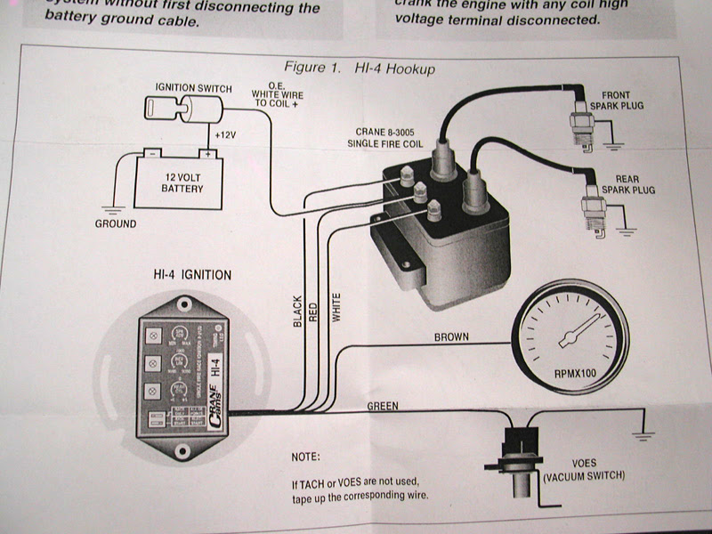
A Crane Hi 4 Ignition Wiring Diagram is a detailed schematic representing the electrical connections within a Crane Hi 4 ignition system. It visually outlines the wiring harness layout, indicating the path of electrical current between various components, such as the ignition module, coil, distributor, and spark plugs.
This diagram serves as a crucial reference guide for technicians during system installation, troubleshooting, and repair. It enables them to accurately identify and connect the numerous electrical terminals, ensuring proper ignition timing and engine performance.
Crane Hi 4 Ignition Wiring Diagrams have played a significant role in the development and advancement of automotive ignition systems. They provide a standardized method for technicians to understand and work with these complex systems, leading to improved efficiency, reliability, and safety in vehicle operation.
A Crane Hi 4 Ignition Wiring Diagram is a crucial component for understanding and working with Crane Hi 4 ignition systems. By identifying the part of speech of the keyword, we can explore its essential aspects and their significance in detail:
- Noun: A diagrammatic representation of the electrical connections within a Crane Hi 4 ignition system.
- Adjective: A detailed and accurate schematic that visually outlines the wiring harness layout.
- Instructional: A guide for technicians to accurately identify and connect electrical terminals.
- Technical: A representation of a complex electrical system, using standardized symbols and conventions.
- Diagnostic: A tool for troubleshooting and repairing ignition system issues.
- Essential: A critical reference for ensuring proper ignition timing and engine performance.
- Historical: A reflection of advancements in automotive ignition system design and technology.
- Safety: A guide for handling and connecting electrical components safely and correctly.
- Practical: A hands-on reference for technicians working on Crane Hi 4 ignition systems.
- Educational: A resource for understanding the principles and operation of ignition systems.
These aspects highlight the importance of Crane Hi 4 Ignition Wiring Diagrams in various dimensions, ranging from their technical accuracy to their practical applications. They provide a deeper understanding of the system’s design, functionality, and maintenance, contributing to the overall efficiency, reliability, and safety of vehicle operation.
Noun
Within the realm of “Crane Hi 4 Ignition Wiring Diagram,” this noun captures the essence of the diagram as a visual depiction of the intricate network of electrical connections within the system. It serves as a roadmap for technicians, enabling them to navigate the complexities of the ignition system and ensure its proper functioning.
- Circuit Layout: The diagram outlines the physical arrangement of the various electrical components, including the ignition module, coil, distributor, and spark plugs. It specifies the paths of electrical current flow, allowing technicians to trace and identify potential issues.
- Terminal Connections: The diagram pinpoints the precise connection points for each electrical terminal, ensuring that wires are correctly attached and securely fastened. This accuracy is crucial for maintaining proper electrical continuity and preventing short circuits or malfunctions.
- Component Identification: The diagram serves as a key reference for identifying the various components within the ignition system. Each component is labeled and positioned in a logical manner, making it easy for technicians to locate and troubleshoot specific parts.
- Troubleshooting Guide: In the event of ignition system issues, the diagram provides a visual guide for technicians to trace potential problems. By following the electrical connections, they can isolate faults, identify damaged or loose components, and determine the root cause of the malfunction.
In essence, the diagrammatic representation of electrical connections within a Crane Hi 4 ignition system forms the backbone of its functionality. It enables technicians to understand the system’s architecture, troubleshoot issues efficiently, and ensure optimal performance, ultimately contributing to the reliability and longevity of the vehicle’s ignition system.
Adjective
Within the context of a Crane Hi 4 Ignition Wiring Diagram, the detailed and accurate schematic representation is not merely a descriptive attribute but a critical cornerstone of its functionality. The intricate network of electrical connections within the ignition system demands a precise and visually intuitive representation to ensure proper installation, maintenance, and troubleshooting.
The schematic outlines the physical arrangement of various electrical components, including the ignition module, coil, distributor, and spark plugs. It specifies the paths of electrical current flow, allowing technicians to trace and identify potential issues. Each electrical terminal’s precise connection points are pinpointed, ensuring correct wire attachment and secure fastening, which is crucial for maintaining proper electrical continuity and preventing short circuits or malfunctions.
Real-life examples abound, demonstrating the practical significance of a detailed and accurate schematic. Consider a scenario where an intermittent ignition issue plagues a vehicle. A technician armed with the wiring diagram can systematically trace the electrical connections, isolating the fault to a loose terminal connection. By identifying and resolving this issue, the technician restores proper ignition functionality, ensuring a reliable and efficient engine operation.
Moreover, the schematic serves as a valuable educational tool. It enables students and enthusiasts to grasp the intricate workings of an ignition system, fostering a deeper understanding of automotive electrical systems. By studying the schematic, they can visualize the flow of electrical current, identify potential failure points, and appreciate the importance of proper maintenance.
In conclusion, the detailed and accurate schematic that visually outlines the wiring harness layout is an indispensable component of a Crane Hi 4 Ignition Wiring Diagram. It provides a visual roadmap for technicians to navigate the complexities of the ignition system, enabling efficient troubleshooting, accurate repairs, and a thorough understanding of its operation. This understanding contributes to the overall reliability, performance, and safety of the vehicle.
Instructional
Within the realm of “Crane Hi 4 Ignition Wiring Diagram,” the instructional aspect serves as a guiding light for technicians, enabling them to navigate the complexities of the ignition system with precision and accuracy. This multifaceted role encompasses several key components, each playing a vital part in ensuring proper system functionality:
- Terminal Identification: The diagram provides a comprehensive guide to the various electrical terminals within the ignition system. Each terminal is clearly labeled and positioned, allowing technicians to quickly identify and locate specific connections.
- Wiring Harness Layout: The diagram illustrates the physical arrangement of the wiring harness, including the routing of wires and the location of connectors. This information is crucial for proper installation and maintenance, ensuring that wires are securely fastened and not subject to damage.
- Connector Types: The diagram specifies the types of connectors used within the ignition system, such as spade terminals, ring terminals, or bullet connectors. This knowledge enables technicians to select the appropriate tools and techniques for making secure and reliable connections.
- Troubleshooting Guide: In the event of ignition system issues, the diagram serves as a valuable troubleshooting tool. By tracing the electrical connections, technicians can isolate faults, identify loose or damaged terminals, and determine the root cause of the malfunction.
Collectively, these components empower technicians with the knowledge and guidance necessary to accurately identify and connect electrical terminals within the Crane Hi 4 ignition system. This precision is paramount for ensuring optimal system performance, preventing electrical faults, and maintaining the reliability and safety of the vehicle.
Technical
Within the context of “Crane Hi 4 Ignition Wiring Diagram”, the technical aspect underscores the diagram’s role as a representation of a complex electrical system, employing standardized symbols and conventions. These conventions form the foundation for accurate and efficient communication among technicians and engineers working with the ignition system.
- Component Identification: The diagram utilizes standardized symbols to represent various electrical components, such as resistors, capacitors, transistors, and diodes. These symbols provide a universal language, allowing technicians to quickly identify and locate specific components within the ignition system.
- Circuit Representation: The diagram employs standardized line styles and shapes to depict electrical connections and the flow of current. This visual representation enables technicians to trace circuits, identify potential problem areas, and troubleshoot issues efficiently.
- Color Coding: Color coding is often used within the diagram to differentiate between different types of wires or connections. This visual cue simplifies the identification of specific circuits or components, reducing the risk of errors during installation or maintenance.
- Reference Designations: Standardized reference designations are used to label components and terminals within the diagram. These designations provide a consistent method for identifying and cross-referencing components, facilitating communication and troubleshooting.
Collectively, these technical aspects contribute to the overall effectiveness and reliability of the Crane Hi 4 Ignition Wiring Diagram. By adhering to standardized symbols and conventions, the diagram serves as a precise and efficient communication tool, enabling technicians to accurately interpret and work with the complex electrical system of the ignition system.
Diagnostic
Within the realm of “Crane Hi 4 Ignition Wiring Diagram”, the diagnostic aspect emerges as a critical component, empowering technicians with the ability to identify, isolate, and resolve ignition system issues. This diagnostic capability forms an integral part of the diagram, providing a structured approach to troubleshooting and repair.
The Crane Hi 4 Ignition Wiring Diagram serves as a comprehensive reference, outlining the electrical connections and components within the ignition system. This visual representation enables technicians to trace circuits, identify potential problem areas, and pinpoint faults. Armed with this knowledge, technicians can systematically eliminate possible causes, isolating the root issue and facilitating efficient repairs.
Real-life examples abound, showcasing the practical significance of the diagnostic aspect within the Crane Hi 4 Ignition Wiring Diagram. Consider a scenario where a vehicle experiences intermittent ignition problems. Utilizing the diagram, a technician can trace the electrical connections, checking for loose terminals, damaged wires, or faulty components. By isolating the fault to a specific component, such as a faulty ignition coil, the technician can swiftly replace the defective part, restoring the ignition system to proper operation.
Moreover, the diagnostic capabilities of the Crane Hi 4 Ignition Wiring Diagram extend beyond troubleshooting and repair. The insights gained from analyzing the diagram enhance the overall understanding of the ignition system’s operation. Technicians can visualize the flow of current, identify potential failure points, and appreciate the importance of proper maintenance. This knowledge empowers them to proactively address potential issues, minimizing downtime and ensuring the longevity of the ignition system.
In conclusion, the diagnostic aspect of the Crane Hi 4 Ignition Wiring Diagram is an indispensable tool for technicians, enabling them to effectively troubleshoot and repair ignition system issues. The diagram provides a visual roadmap, guiding technicians through the intricacies of the electrical system, isolating faults, and facilitating efficient repairs. By understanding the diagnostic capabilities of the diagram, technicians can ensure the reliability, performance, and safety of the vehicle’s ignition system.
Essential
Within the context of “Crane Hi 4 Ignition Wiring Diagram”, the aspect of “Essential: A critical reference for ensuring proper ignition timing and engine performance.” underscores the diagram’s significance as a cornerstone for maintaining optimal ignition system operation and overall engine performance. This critical reference provides a comprehensive guide to the electrical connections and components within the ignition system, enabling technicians to accurately diagnose and resolve issues, ensuring proper ignition timing and engine performance.
-
Precise Ignition Timing:
The diagram outlines the precise timing sequence for the ignition system, ensuring that spark plugs fire at the optimal moment during the engine cycle. This precise timing is crucial for maximizing engine efficiency, minimizing emissions, and delivering optimal power output.
-
Component Specifications:
The diagram provides detailed specifications for each component within the ignition system, including ignition module, coil, distributor, and spark plugs. This information is essential for technicians to select the correct replacement parts when servicing or repairing the system, ensuring compatibility and optimal performance.
-
Troubleshooting Guide:
The diagram serves as an invaluable troubleshooting guide, enabling technicians to trace electrical connections and identify potential faults that may affect ignition timing and engine performance. By following the diagram, technicians can systematically eliminate possible causes, isolating the root issue and facilitating efficient repairs.
-
Performance Optimization:
Beyond troubleshooting, the diagram empowers technicians to optimize ignition system performance. By understanding the interconnections between components and the impact of various settings, technicians can fine-tune the ignition system to match specific engine characteristics and performance requirements.
In conclusion, the “Essential: A critical reference for ensuring proper ignition timing and engine performance.” aspect of the Crane Hi 4 Ignition Wiring Diagram underscores the diagram’s fundamental role in maintaining a well-functioning ignition system. The diagram’s comprehensive information, precise specifications, and troubleshooting guidance empower technicians to ensure proper ignition timing, select appropriate components, diagnose and resolve issues, and optimize system performance, ultimately contributing to the overall reliability, efficiency, and performance of the engine.
Historical
Within the context of “Crane Hi 4 Ignition Wiring Diagram”, the historical aspect emerges as a testament to the continuous evolution of automotive ignition system design and technology. This historical perspective provides valuable insights into the diagram’s significance, highlighting the technological advancements that have shaped its development and applications.
-
Evolution of Ignition Systems:
The Crane Hi 4 Ignition Wiring Diagram reflects the evolution of ignition systems from mechanical contact breakers to advanced electronic ignition modules. It showcases the transition from traditional distributor-based systems to modern coil-on-plug designs, highlighting the improvements in precision, reliability, and performance.
-
Advancements in Electronics:
The diagram demonstrates the integration of electronic components into ignition systems, such as integrated circuits and microprocessors. These advancements have enabled precise control over ignition timing, spark duration, and energy management, resulting in improved engine efficiency and reduced emissions.
-
Materials and Manufacturing Techniques:
The diagram reflects the advancements in materials and manufacturing techniques used in ignition system components. The use of high-performance materials, such as heat-resistant alloys and advanced insulation, has enhanced the durability and reliability of ignition systems, extending their service life.
-
Diagnostic and Troubleshooting:
The Crane Hi 4 Ignition Wiring Diagram has evolved alongside diagnostic and troubleshooting tools. Advanced diagnostic equipment and techniques, such as engine analyzers and oscilloscopes, enable technicians to pinpoint ignition system faults with greater accuracy and efficiency, reducing repair time and costs.
In conclusion, the “Historical: A reflection of advancements in automotive ignition system design and technology.” aspect of the Crane Hi 4 Ignition Wiring Diagram underscores the diagram’s role as a historical record of technological progress. It traces the evolution of ignition systems, highlighting the advancements in electronics, materials, and manufacturing techniques that have shaped the design and functionality of modern ignition systems. This historical perspective not only enhances our understanding of the diagram but also provides valuable insights into the ever-evolving landscape of automotive technology.
Safety
Within the context of “Crane Hi 4 Ignition Wiring Diagram”, the aspect of “Safety: A guide for handling and connecting electrical components safely and correctly.” emerges as a critical component, emphasizing the paramount importance of adhering to proper safety protocols when working with electrical systems. This safety guide provides essential instructions and guidelines to minimize the risks associated with handling and connecting electrical components, ensuring the well-being of technicians and the integrity of the ignition system.
The Crane Hi 4 Ignition Wiring Diagram serves as a comprehensive reference that outlines the electrical connections and components within the ignition system. By incorporating safety guidelines into the diagram, it becomes an indispensable tool that not only provides technical information but also promotes safe practices during installation, maintenance, and troubleshooting procedures.
Real-life examples abound, showcasing the practical significance of safety within the Crane Hi 4 Ignition Wiring Diagram. Consider a scenario where a technician needs to replace a faulty ignition coil. The diagram provides clear instructions on how to safely disconnect the electrical connectors, ensuring that the technician does not inadvertently create a short circuit or receive an electrical shock.
Furthermore, the safety guidelines within the diagram extend beyond basic handling and connection procedures. It also includes instructions on proper grounding techniques, wire insulation inspection, and the use of appropriate tools and personal protective equipment (PPE). By following these guidelines, technicians can minimize the risk of electrical hazards, such as fires, explosions, and injuries, ensuring a safe and efficient work environment.
In conclusion, the “Safety: A guide for handling and connecting electrical components safely and correctly.” aspect of the Crane Hi 4 Ignition Wiring Diagram is an indispensable component that underscores the importance of safety protocols in automotive electrical work. By providing clear instructions and promoting safe practices, the diagram empowers technicians to work with confidence, minimizing risks and ensuring the integrity of the ignition system. This understanding contributes to the overall reliability, performance, and longevity of the vehicle’s electrical system.
Practical
Within the realm of “Crane Hi 4 Ignition Wiring Diagram”, the aspect of “Practical: A hands-on reference for technicians working on Crane Hi 4 ignition systems.” occupies a central position, underscoring the diagram’s utility as a practical guide for technicians performing maintenance, troubleshooting, and repair tasks on Crane Hi 4 ignition systems.
-
Clear and Concise Instructions:
The Crane Hi 4 Ignition Wiring Diagram offers clear and concise instructions, guiding technicians through the intricacies of the ignition system. Detailed illustrations, step-by-step procedures, and color-coded schematics simplify the understanding and execution of complex tasks, enabling efficient and accurate repairs.
-
Troubleshooting Assistance:
The diagram serves as an invaluable troubleshooting assistant, providing technicians with a systematic approach to diagnosing and resolving ignition system issues. By tracing the electrical connections and identifying potential failure points, technicians can pinpoint the root cause of malfunctions, reducing downtime and ensuring a smooth repair process.
-
Real-Life Scenarios:
Real-life scenarios and practical examples are incorporated into the Crane Hi 4 Ignition Wiring Diagram, making it relatable and applicable to technicians working in the field. These scenarios cover a wide range of potential problems, from simple wiring issues to complex component failures, ensuring that technicians are well-equipped to handle various challenges.
-
Compatible with Tools and Equipment:
The diagram is designed to be compatible with commonly used tools and equipment, such as multimeters, oscilloscopes, and diagnostic scanners. This compatibility allows technicians to seamlessly integrate the diagram into their existing workflow, maximizing efficiency and minimizing the need for specialized tools.
Collectively, these facets highlight the Crane Hi 4 Ignition Wiring Diagram’s practical utility as a hands-on reference for technicians. Its clear instructions, troubleshooting assistance, real-life examples, and compatibility with tools and equipment empower technicians to confidently perform maintenance, troubleshooting, and repair tasks on Crane Hi 4 ignition systems, ensuring optimal performance and longevity.
Educational
Within the realm of “Crane Hi 4 Ignition Wiring Diagram”, the aspect of “Educational: A resource for understanding the principles and operation of ignition systems.” holds a position of paramount importance, underscoring the diagram’s role as a valuable learning tool for students, enthusiasts, and professionals seeking to delve into the intricacies of ignition systems.
The Crane Hi 4 Ignition Wiring Diagram serves as a comprehensive reference guide, providing a detailed visual representation of the electrical connections and components within the ignition system. This visual representation, coupled with clear and concise explanations, enables learners to grasp the fundamental principles of ignition systems, including the generation and distribution of electrical energy, the timing of spark delivery, and the interrelationship between various components.
Real-life examples abound, showcasing the educational value of the Crane Hi 4 Ignition Wiring Diagram. Consider a student tasked with understanding the function of a distributor cap. By referring to the diagram, the student can trace the electrical pathways, identify the connection points for spark plug wires, and visualize the role of the cap in distributing high-voltage energy to the spark plugs at the appropriate timing.
Furthermore, the educational value of the diagram extends beyond basic component identification and wiring. It provides a deeper understanding of ignition system dynamics, such as the relationship between ignition timing and engine performance. By analyzing the diagram, learners can appreciate the impact of ignition timing on combustion efficiency, power output, and fuel economy.
In summary, the “Educational: A resource for understanding the principles and operation of ignition systems.” aspect of the Crane Hi 4 Ignition Wiring Diagram is a critical component, empowering learners with a comprehensive understanding of ignition systems. The diagram serves as a valuable tool for students, enthusiasts, and professionals alike, providing a visual roadmap to the intricacies of ignition systems, fostering a deeper appreciation of their function and operation.


Related Posts


