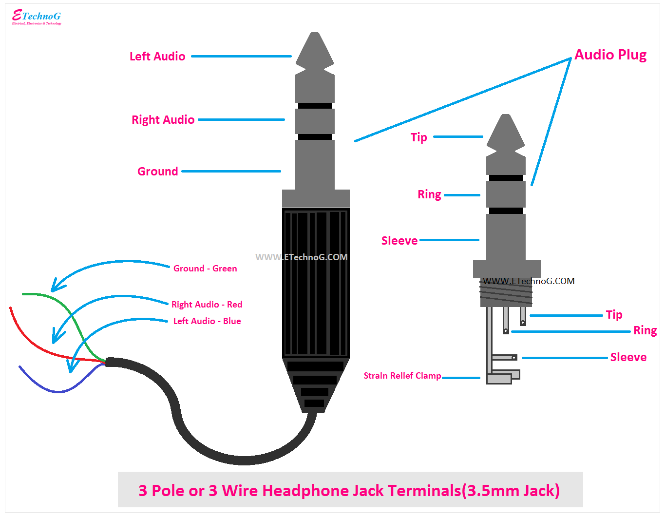
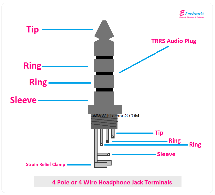
A 4-pole headphone jack wiring diagram illustrates the connections and arrangement of the four conductors within a 4-pole headphone jack connector. It provides a guide for understanding and correctly wiring such connectors, ensuring proper functionality of headphones or other audio devices that utilize them.
The four conductors in a 4-pole headphone jack typically serve specific functions: left audio channel, right audio channel, ground, and microphone (for headsets with an integrated microphone). Proper wiring allows for accurate signal transmission and reception between the audio source and the headphones, enabling stereo sound output and, in some cases, microphone input capabilities.
This wiring diagram is essential for manufacturers, repair technicians, and hobbyists involved in audio equipment design, maintenance, and repair. It ensures compatibility and optimal audio performance when connecting headphones, headsets, or other devices to audio sources such as smartphones, laptops, and audio mixers.
The “4 Pole Headphone Jack Wiring Diagram” is a crucial aspect of audio engineering and device connectivity. Understanding its key aspects is essential for ensuring proper functionality and compatibility of audio devices.
- Conductor Configuration: Specifies the arrangement and insulation of the four conductors within the jack – left audio, right audio, ground, and microphone.
- Pin Assignments: Defines the specific pin connections for each conductor, ensuring correct signal routing and compatibility with devices.
- Connector Standards: Adheres to industry standards such as TRS (Tip-Ring-Sleeve) and TRRS (Tip-Ring-Ring-Sleeve) to ensure compatibility across different devices.
- Signal Transmission: Describes the electrical signals transmitted through each conductor, including audio channels and microphone input.
- Stereo Sound Output: Explains how the diagram facilitates the transmission of separate left and right audio channels for stereo sound reproduction.
- Microphone Integration: Illustrates the wiring for headsets that incorporate a microphone, allowing for voice communication and audio input.
- Headphone Compatibility: Guides the selection of compatible headphones based on the wiring diagram and plug type.
- Troubleshooting and Repair: Provides insights for diagnosing and resolving issues related to headphone jack connections and wiring.
These aspects are interconnected and contribute to the effective functioning of 4-pole headphone jack wiring diagrams. By understanding these details, manufacturers, technicians, and users can ensure optimal audio performance and compatibility in various applications.
Conductor Configuration
In the context of “4 Pole Headphone Jack Wiring Diagram,” the conductor configuration refers to the specific arrangement and insulation of the four individual conductors within the jack. Each conductor serves a distinct purpose in transmitting audio signals and ensuring proper functionality of headphones or other audio devices.
- Conductor Insulation: Each conductor is coated with an insulating material, typically plastic or enamel, to prevent electrical shorts and ensure signal integrity. Proper insulation is crucial for maintaining clear audio transmission and preventing interference.
- Conductor Arrangement: The four conductors are arranged in a specific order within the jack, typically following the Tip-Ring-Ring-Sleeve (TRRS) or Tip-Ring-Sleeve (TRS) configuration. This arrangement ensures compatibility with corresponding plugs and allows for the proper routing of audio signals.
- Conductor Materials: The conductors are typically made of copper or copper alloys, which provide excellent electrical conductivity and durability. The choice of conductor material affects the overall signal quality and durability of the headphone jack.
- Conductor Gauge: The gauge of the conductors refers to their thickness, which determines the amount of current they can carry. Proper conductor gauge is essential for handling the required audio signals without introducing distortion or signal loss.
The conductor configuration plays a vital role in ensuring reliable and high-quality audio transmission in 4-pole headphone jack applications. Understanding and adhering to the specified conductor configuration is crucial for manufacturers, repair technicians, and users to achieve optimal performance and compatibility.
Pin Assignments
Within the framework of “4 Pole Headphone Jack Wiring Diagram,” “Pin Assignments” plays a crucial role in establishing the designated electrical connections for each conductor within the jack. These assignments are essential for ensuring proper signal routing and compatibility between headphones, headsets, and audio devices.
- Conductor Designation: Pin assignments specify which pin on the jack corresponds to each conductor, typically following industry standards such as TRS (Tip-Ring-Sleeve) or TRRS (Tip-Ring-Ring-Sleeve). This designation ensures that the left audio channel, right audio channel, ground, and microphone (if present) are connected to the correct pins.
- Compatibility with Devices: Proper pin assignments are critical for compatibility with various devices. By adhering to standardized pinouts, manufacturers can ensure that headphones and headsets can be plugged into different audio sources, such as smartphones, laptops, and audio interfaces, without any issues.
- Signal Integrity: Correct pin assignments maintain signal integrity by preventing misconnections and ensuring that audio signals are routed to the appropriate channels. This minimizes noise, distortion, and other audio impairments.
- Headset Functionality: For headsets with integrated microphones, pin assignments are particularly important. The correct assignment of the microphone pin allows for proper audio input and communication capabilities, enabling features like voice calls and video conferencing.
Overall, “Pin Assignments: Defines the specific pin connections for each conductor, ensuring correct signal routing and compatibility with devices.” is a vital aspect of “4 Pole Headphone Jack Wiring Diagram.” It lays the foundation for reliable and seamless audio transmission, ensuring that headphones and headsets function as intended when connected to various audio devices.
Connector Standards
Within the context of “4 Pole Headphone Jack Wiring Diagram,” connector standards play a critical role in ensuring compatibility and seamless connectivity across various devices. The adherence to industry standards, such as TRS (Tip-Ring-Sleeve) and TRRS (Tip-Ring-Ring-Sleeve), serves as a cornerstone of effective headphone jack wiring.
TRS and TRRS are widely adopted configurations for 3-pole and 4-pole headphone jacks, respectively. These standards define the arrangement and functionality of the conductors within the jack, ensuring that left audio, right audio, ground, and (in the case of TRRS) microphone signals are routed correctly.
By adhering to these standards, manufacturers can guarantee that headphones and other audio devices can be plugged into different sources, such as smartphones, laptops, and audio mixers, without any compatibility issues. This standardization simplifies the design and production of audio equipment, ensuring a consistent user experience across different brands and models.
Furthermore, connector standards facilitate the development of accessories, such as extension cables and adapters. By conforming to TRS or TRRS configurations, these accessories can be used with a wide range of headphones and devices, providing greater flexibility and convenience for users.
In summary, connector standards are a crucial component of “4 Pole Headphone Jack Wiring Diagram.” They ensure compatibility across different devices, simplify the design and production of audio equipment, and enable the development of useful accessories. Understanding these standards is essential for manufacturers, technicians, and users alike to achieve optimal performance and seamless audio connectivity.
Signal Transmission
Within the context of “4 Pole Headphone Jack Wiring Diagram,” signal transmission plays a fundamental role in understanding the flow of electrical signals through each conductor. This aspect of the wiring diagram outlines the specific electrical characteristics and functions of each conductor, enabling effective audio transmission and microphone input capabilities.
Cause and Effect: The proper wiring of conductors according to the signal transmission specifications ensures that audio signals from the source device (e.g., smartphone, laptop) are accurately transmitted to the headphones. This involves maintaining the correct signal polarity and impedance matching to preserve audio quality and prevent distortion or noise.
Critical Component: Signal transmission is a critical component of “4 Pole Headphone Jack Wiring Diagram” as it directly affects the performance and functionality of headphones or headsets. Without a clear understanding of the electrical signals transmitted through each conductor, it is impossible to design and implement effective headphone jack wiring.
Real-Life Example: In a 4-pole headphone jack, the left and right audio channels are transmitted through separate conductors. This separation ensures stereo sound reproduction, allowing users to experience spatial audio effects and immersive listening experiences.
Practical Applications: Understanding signal transmission in headphone jack wiring diagrams has practical applications in various fields. For instance, in audio engineering, it enables technicians to troubleshoot and resolve issues related to audio signal transmission, ensuring optimal sound quality in live performances, recording studios, and broadcasting systems.
In summary, the “Signal Transmission: Describes the electrical signals transmitted through each conductor, including audio channels and microphone input” aspect of “4 Pole Headphone Jack Wiring Diagram” provides a detailed understanding of the electrical signals that flow through each conductor. This knowledge is crucial for designing, implementing, and maintaining headphone jack connections, ultimately contributing to high-quality audio transmission and microphone input capabilities in various applications.
Stereo Sound Output
Within the realm of “4 Pole Headphone Jack Wiring Diagram,” the aspect of “Stereo Sound Output” plays a pivotal role in understanding how the diagram enables the seamless transmission of distinct left and right audio channels for an immersive stereo sound experience.
- Channel Separation: The diagram specifies the wiring configuration that ensures the isolation of left and right audio signals throughout the transmission path. This separation prevents crosstalk and maintains the integrity of each audio channel, resulting in a clear and well-defined stereo soundscape.
- Conductor Configuration: The diagram outlines the specific arrangement of conductors within the 4-pole jack, dedicating separate conductors for left and right audio channels. This configuration allows for the independent transmission of each channel’s electrical signals, preserving the spatial separation of audio elements.
- Connector Standards: Adherence to industry standards, such as TRS and TRRS, ensures compatibility across various devices. These standards define the pin assignments for each audio channel, guaranteeing proper connection and signal routing, regardless of the specific device or headphone model.
- Real-Life Application: In practical applications, stereo sound output enhances the listening experience in numerous settings. From enjoying music with spatial depth to experiencing immersive soundscapes in movies and games, stereo sound reproduction brings audio to life, creating a more engaging and enjoyable auditory experience.
In summary, the “Stereo Sound Output: Explains how the diagram facilitates the transmission of separate left and right audio channels for stereo sound reproduction” aspect of “4 Pole Headphone Jack Wiring Diagram” provides a comprehensive understanding of the technical and practical implications of achieving stereo sound output through headphone jack connections. This aspect is essential for manufacturers, audio engineers, and users alike to design, implement, and utilize headphone connections effectively, ensuring high-quality and immersive audio experiences.
Microphone Integration
Within the realm of “4 Pole Headphone Jack Wiring Diagram,” the aspect of “Microphone Integration” holds significant importance in enabling communication and audio input capabilities for headsets and other devices.
Cause and Effect: The microphone integration aspect of the diagram provides detailed instructions on how to wire the fourth conductor in a 4-pole headphone jack specifically for microphone input. This allows manufacturers to design headsets that incorporate a microphone, enabling users to engage in voice communication and audio recording.
Critical Component: Microphone integration is a critical component of “4 Pole Headphone Jack Wiring Diagram” for headsets that require audio input functionality. Without proper wiring and configuration, the microphone will not be able to transmit audio signals, limiting the headset’s capabilities.
Real-Life Examples: Headsets with integrated microphones are widely used in various applications, including customer service, gaming, podcasting, and remote work. The microphone integration aspect of the wiring diagram enables these devices to function effectively, allowing users to communicate clearly and record audio.
Practical Applications: Understanding microphone integration in 4-pole headphone jack wiring diagrams is crucial for manufacturers, audio engineers, and users. It ensures that headsets with microphone capabilities are designed, wired, and used correctly, enabling seamless voice communication and audio input across various devices and applications.
Summary: The “Microphone Integration: Illustrates the wiring for headsets that incorporate a microphone, allowing for voice communication and audio input.” aspect of “4 Pole Headphone Jack Wiring Diagram” is essential for understanding how to wire and utilize headsets with microphone capabilities. It provides the technical foundation for effective audio input and communication, enabling a wide range of applications and enhancing the user experience.
Headphone Compatibility
Within the context of “4 Pole Headphone Jack Wiring Diagram,” headphone compatibility plays a crucial role in ensuring that the headphones used are compatible with the wiring diagram and the output device. This compatibility aspect of the wiring diagram guides manufacturers, users, and audio professionals in selecting the appropriate headphones for optimal performance and functionality.
- Plug Type Compatibility: The wiring diagram specifies the type of plug that is compatible with the jack. Common plug types include TRS (Tip-Ring-Sleeve) and TRRS (Tip-Ring-Ring-Sleeve), each with a different number of conductors and configurations. This compatibility ensures that the headphones have the correct plug type to match the wiring diagram and the output device.
- Conductor Configuration: The wiring diagram outlines the arrangement and functionality of each conductor within the jack. Headphones must have a compatible conductor configuration to match the wiring diagram. Mismatched conductor configurations can result in incorrect audio channel mapping, microphone issues, or no audio output.
- Impedance Matching: The wiring diagram may specify the impedance of the headphones that are compatible with the output device. Impedance matching is important to ensure proper signal transmission and to avoid distortion or volume issues. Headphones with mismatched impedance can lead to reduced audio quality or damage to the output device.
- Real-Life Examples: In practice, headphone compatibility is crucial for various applications. For instance, in professional audio setups, ensuring headphone compatibility is essential for accurate audio monitoring and mixing. In gaming, compatible headphones provide immersive audio experiences, enhancing gameplay. Additionally, in mobile devices, headphone compatibility enables users to enjoy music, make calls, and engage in other audio-related activities.
Understanding headphone compatibility in relation to “4 Pole Headphone Jack Wiring Diagram” is essential for manufacturers, audio engineers, and users alike. It ensures that headphones and output devices are correctly matched for optimal performance, compatibility, and user satisfaction.
Troubleshooting and Repair
Within the realm of “4 Pole Headphone Jack Wiring Diagram,” troubleshooting and repair play a crucial role in maintaining optimal performance and resolving issues related to headphone jack connections and wiring. The insights provided in the troubleshooting and repair aspect of the diagram empower users, technicians, and manufacturers to diagnose and address common problems, ensuring seamless audio experiences.
- Cause and Effect: Troubleshooting and repair are essential components of “4 Pole Headphone Jack Wiring Diagram” as they provide guidance on identifying and resolving issues that may arise due to improper wiring, faulty connections, or damaged components. Understanding the cause-and-effect relationships outlined in the diagram enables effective troubleshooting and repair.
- Critical Component: The troubleshooting and repair aspect of the diagram is a critical component as it provides valuable insights into potential issues and their solutions. Without a clear understanding of troubleshooting techniques and repair procedures, resolving headphone jack problems can be challenging, leading to poor audio quality or even damage to the equipment.
- Real-Life Examples: Within the context of “4 Pole Headphone Jack Wiring Diagram,” troubleshooting and repair find practical applications in various scenarios. For instance, if one experiences audio distortion or intermittent sound, the diagram can guide in identifying loose connections, faulty wiring, or damaged jacks, facilitating effective repairs.
- Practical Applications: Understanding troubleshooting and repair techniques is beneficial for both manufacturers and users. Manufacturers can improve product reliability and user satisfaction by incorporating robust troubleshooting and repair guidelines into their documentation. Users, on the other hand, can diagnose and resolve minor issues , saving time and resources.
In summary, “Troubleshooting and Repair: Provides insights for diagnosing and resolving issues related to headphone jack connections and wiring” is a vital aspect of “4 Pole Headphone Jack Wiring Diagram.” It empowers users, technicians, and manufacturers to maintain optimal audio performance, resolve common problems, and extend the lifespan of headphone jack connections and equipment.


Related Posts


