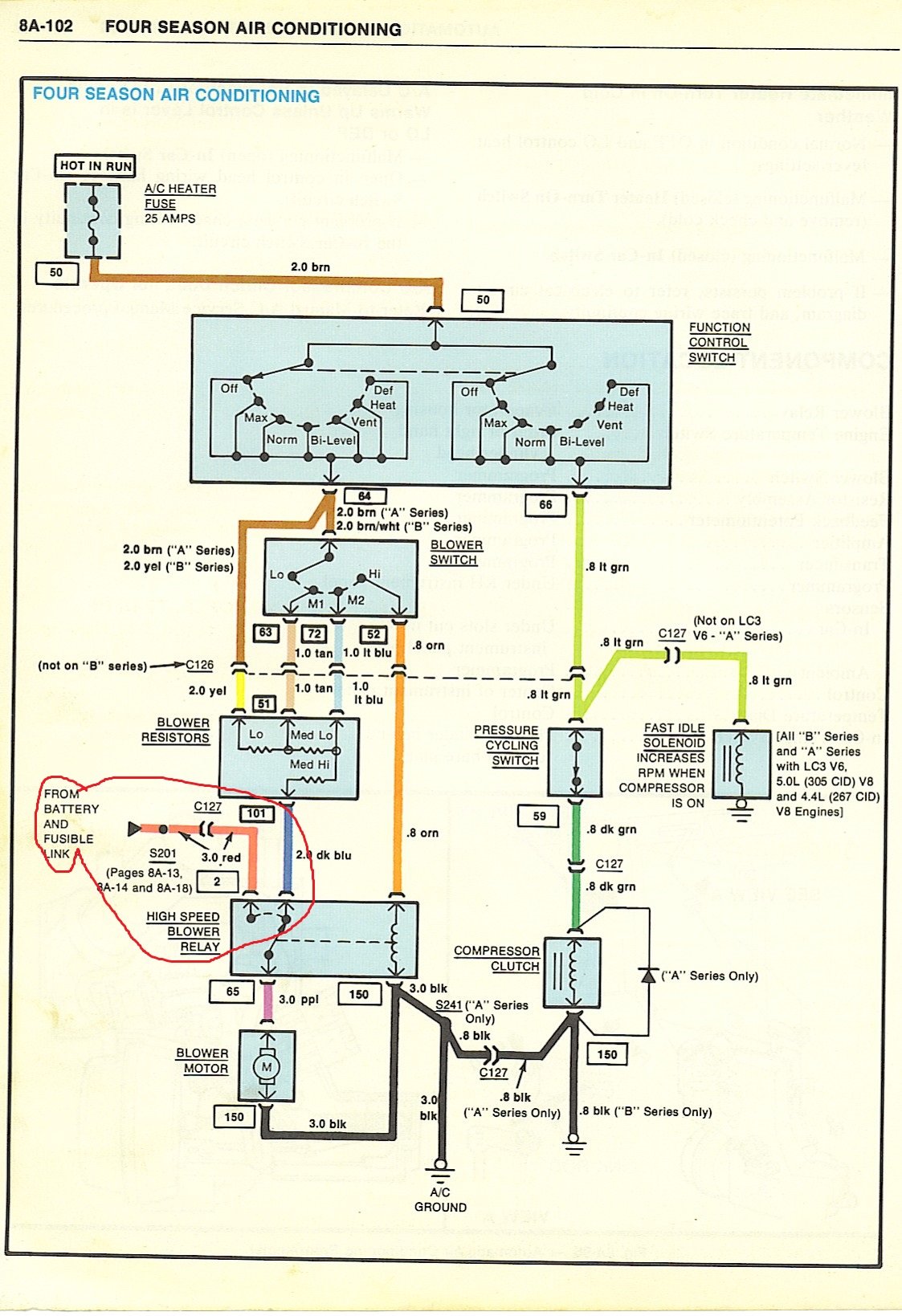
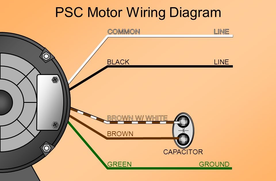
A 4 Wire Blower Motor Wiring Diagram outlines the electrical connections for a blower motor with four wires. It specifies the wire colors, terminals, and voltage levels required for proper operation.
This diagram is essential for installing, troubleshooting, and maintaining blower motors in various applications, such as HVAC systems, industrial fans, and automotive cooling systems. By following the diagram, it ensures the correct wiring connections, preventing electrical hazards, motor damage, and optimal performance.
A key historical development in blower motor wiring diagrams was the standardization of wire colors. This standardization, such as the color-coded wiring of the National Electrical Code (NEC), facilitates easy identification, reduces wiring errors, and enhances safety.
Understanding the essential aspects of a 4 Wire Blower Motor Wiring Diagram is crucial for ensuring proper installation, troubleshooting, and maintenance of blower motors in various applications. These key aspects encompass:
- Wire Colors: Standardized color-coding simplifies identification and reduces wiring errors.
- Terminals: Clearly labeled terminals guide proper wire connections and prevent incorrect wiring.
- Voltage Levels: Specified voltage levels ensure compatibility with the power source and prevent motor damage.
- Circuit Protection: Fuses or circuit breakers protect the motor from electrical overloads.
- Grounding: Proper grounding ensures safety and prevents electrical shock hazards.
- Switching: Diagrams specify the type of switch required to control the motor’s operation.
- Motor Connections: Diagrams outline the specific connections between the motor and the wiring.
- Troubleshooting Guide: Diagrams often include troubleshooting tips to assist in diagnosing and resolving common issues.
These aspects are interconnected and essential for the safe and efficient operation of blower motors. By adhering to the guidelines outlined in a 4 Wire Blower Motor Wiring Diagram, technicians can ensure proper installation, prevent costly mistakes, and extend the lifespan of the motor.
Wire Colors
In the context of 4 Wire Blower Motor Wiring Diagrams, standardized wire colors play a crucial role in simplifying identification and reducing wiring errors. This color-coding system ensures that each wire has a specific color, making it easier to differentiate between them and connect them correctly.
- Identification: Standardized wire colors facilitate quick and accurate identification of each wire’s function. For example, in many regions, black wires typically indicate line voltage, white wires represent neutral, and green wires signify ground.
- Consistency: Color standardization ensures consistency across different manufacturers and applications. This allows technicians to easily follow wiring diagrams and make connections without confusion or errors.
- Safety: Correct wire identification is essential for safety. Standardized wire colors help prevent accidental misconnections that could lead to electrical hazards, such as short circuits or shocks.
- Efficiency: Color-coded wires save time and effort during installation and maintenance. Technicians can quickly identify and trace wires, reducing the likelihood of mistakes and speeding up the process.
In summary, standardized wire colors in 4 Wire Blower Motor Wiring Diagrams serve as a vital tool for accurate identification, error reduction, safety enhancement, and efficient wiring. This color-coding system simplifies the installation, troubleshooting, and maintenance of blower motors, ensuring proper operation and longevity.
Terminals
In the context of 4 Wire Blower Motor Wiring Diagrams, clearly labeled terminals play a critical role in ensuring proper wire connections and preventing incorrect wiring. These terminals, which are typically located on the motor itself or on a separate terminal block, serve as the connection points for the wires that carry power to the motor and control its operation.
- Identification: Clearly labeled terminals make it easy to identify the purpose of each terminal, such as line voltage, neutral, ground, or control wires. This facilitates quick and accurate wiring.
- Consistency: Standardized terminal labeling ensures consistency across different manufacturers and applications. This allows technicians to easily follow wiring diagrams and make connections without confusion or errors.
- Safety: Correct terminal identification is essential for safety. Clearly labeled terminals help prevent accidental misconnections that could lead to electrical hazards, such as short circuits or shocks.
- Efficiency: Labeled terminals save time and effort during installation and maintenance. Technicians can quickly identify and connect wires to the appropriate terminals, reducing the likelihood of mistakes and speeding up the process.
In summary, clearly labeled terminals in 4 Wire Blower Motor Wiring Diagrams are essential for ensuring proper wire connections and preventing incorrect wiring. This labeling system simplifies the installation, troubleshooting, and maintenance of blower motors, ensuring safe and efficient operation.
Voltage Levels
Within the context of “4 Wire Blower Motor Wiring Diagram”, voltage levels play a critical role in ensuring compatibility with the power source and preventing potential damage to the motor. These diagrams specify the voltage levels required for proper operation, taking into account factors such as the motor’s design, power requirements, and safety considerations.
- Matching Power Source: The voltage level specified in the wiring diagram must match the voltage of the power source to which the motor will be connected. Using an incorrect voltage can lead to motor damage or failure.
- Motor Compatibility: The motor’s design determines the voltage range it can safely handle. Wiring diagrams specify the compatible voltage levels to ensure that the motor operates within its intended parameters.
- Safety Considerations: Voltage levels must adhere to safety regulations and standards to prevent electrical hazards. Wiring diagrams account for these requirements to ensure safe operation.
- Performance Optimization: Operating the motor at the correct voltage level optimizes its performance, efficiency, and lifespan. Deviations from the specified voltage can result in reduced performance or premature motor failure.
In summary, voltage levels specified in “4 Wire Blower Motor Wiring Diagrams” are crucial for ensuring compatibility with the power source, preventing motor damage, optimizing performance, and adhering to safety regulations. Understanding and adhering to these voltage specifications is essential for the safe and efficient operation of blower motors.
Circuit Protection
In the context of “4 Wire Blower Motor Wiring Diagram,” circuit protection plays a vital role in safeguarding the motor from electrical overloads, ensuring its safe and reliable operation. These diagrams incorporate protective devices such as fuses or circuit breakers to prevent damage to the motor and potential hazards.
- Fuse Protection: Fuses are sacrificial devices designed to interrupt the electrical circuit when excessive current flows, protecting the motor from overloads. When a fuse blows, it must be replaced to restore power to the circuit.
- Circuit Breaker Protection: Circuit breakers are reusable protective devices that automatically trip to interrupt the circuit when an overload occurs. Unlike fuses, they can be reset to restore power without requiring replacement.
- Overload Protection: Circuit protection devices are calibrated to trip or blow at a predetermined current threshold, preventing the motor from drawing excessive current that could cause overheating, insulation damage, or burnout.
- Compliance with Regulations: Incorporating circuit protection into “4 Wire Blower Motor Wiring Diagrams” is essential to comply with electrical codes and safety standards, ensuring the safe installation and operation of blower motors.
By incorporating circuit protection into “4 Wire Blower Motor Wiring Diagrams,” electrical professionals can ensure the safe and reliable operation of blower motors, protecting them from electrical overloads and potential hazards. These diagrams serve as a vital guide for proper installation and maintenance, promoting electrical safety and extending the lifespan of blower motors.
Grounding
In the context of “4 Wire Blower Motor Wiring Diagram,” grounding plays a critical role in ensuring the safe and reliable operation of blower motors. Proper grounding provides a low-resistance path for electrical current to flow back to the power source, protecting against electrical shock hazards and potential damage to equipment.
- Grounding Wire: A dedicated grounding wire, typically bare or green in color, connects the motor frame to the electrical ground system, providing a direct path for fault currents.
- Grounding Terminal: The motor’s terminal block includes a designated grounding terminal specifically for connecting the grounding wire, ensuring a secure and reliable connection.
- Grounding Rod: In many installations, a grounding rod is driven into the earth near the blower motor. The grounding wire is connected to the grounding rod, establishing a solid connection to the earth’s electrical potential.
- Safety Function: In the event of a fault or electrical leakage, the grounding system provides a safe path for excess current to dissipate, preventing it from flowing through other components or the motor housing, which could create hazardous conditions.
Proper grounding, as outlined in “4 Wire Blower Motor Wiring Diagram,” is essential for the safe operation of blower motors. By establishing a low-resistance path to ground, it minimizes the risk of electrical shock, protects equipment from damage, and ensures the reliable and efficient operation of blower motors.
Switching
Within the context of “4 Wire Blower Motor Wiring Diagram”, the aspect of switching holds significant importance in controlling the motor’s operation. Wiring diagrams provide crucial information about the type of switch required, ensuring proper functionality, safety, and efficient motor performance.
- Switch Types: Diagrams specify the type of switch, such as a simple on/off switch, a multi-speed switch, or a reversing switch, based on the desired control requirements.
- Switch Location: Diagrams indicate the location of the switch, whether it is mounted directly on the motor, remotely located, or integrated into a control panel, considering factors like accessibility and ease of use.
- Circuit Compatibility: Diagrams ensure compatibility between the switch and the motor circuit, accounting for current ratings, voltage levels, and any additional control components, preventing potential damage.
- Safety Features: Diagrams may include safety features such as interlocks or emergency stop switches, enhancing overall system safety and preventing unauthorized or hazardous operation.
By providing detailed specifications for switching components, “4 Wire Blower Motor Wiring Diagrams” empower technicians to select and install the appropriate switches, ensuring optimal motor control, safety, and efficiency. These diagrams serve as a vital guide for proper system design, installation, and maintenance, contributing to the reliable and safe operation of blower motors in various applications.
Motor Connections
In the context of “4 Wire Blower Motor Wiring Diagram,” motor connections play a fundamental role in establishing a proper electrical pathway between the motor and the power source. These diagrams provide detailed instructions on how to connect the motor’s terminals to the appropriate wires, ensuring optimal performance and safe operation.
- Terminal Identification: Diagrams clearly label the motor’s terminals, such as L1, L2, N, and GND, guiding technicians in connecting the wires to the correct terminals based on their functions.
- Wire Color Coding: Diagrams use standardized wire color coding to simplify identification and prevent errors. For instance, black wires typically represent line voltage, white wires indicate neutral, and green wires signify ground.
- Connector Types: Diagrams specify the types of connectors required for each connection, such as crimp terminals, solderless connectors, or screw terminals, ensuring secure and reliable electrical contacts.
- Grounding Requirements: Diagrams emphasize the importance of proper grounding to prevent electrical hazards. They indicate the grounding terminal on the motor and provide instructions for connecting the grounding wire to an appropriate grounding point.
Understanding and adhering to motor connection guidelines outlined in “4 Wire Blower Motor Wiring Diagrams” is crucial for ensuring the safe and efficient operation of blower motors. Proper connections prevent electrical faults, motor damage, and potential hazards, contributing to the overall reliability and lifespan of the system.
Troubleshooting Guide
Within the context of “4 Wire Blower Motor Wiring Diagram”, the troubleshooting guide is an invaluable resource for technicians and homeowners alike. It provides a structured approach to identifying and resolving common problems that may arise during the installation, operation, or maintenance of blower motors.
- Error Codes and Descriptions: Troubleshooting guides often include a table of error codes and their corresponding descriptions. This helps technicians quickly identify the nature of the problem and narrow down the potential causes.
- Step-by-Step Troubleshooting Procedures: The guide provides detailed, step-by-step procedures for troubleshooting various issues. These procedures typically involve checking specific components, measuring voltages, and performing continuity tests.
- Real-Life Examples: Troubleshooting guides often include real-life examples of common problems and their solutions. These examples help technicians relate the troubleshooting procedures to situations, making the process more practical and relatable.
- Safety Precautions: Troubleshooting guides emphasize the importance of safety precautions when working with electrical equipment. They provide clear instructions on how to isolate the motor, discharge capacitors, and ground the system before performing any troubleshooting.
By incorporating a troubleshooting guide into “4 Wire Blower Motor Wiring Diagram”, technicians are equipped with the knowledge and resources necessary to diagnose and resolve common issues efficiently and safely. This not only saves time and reduces downtime but also ensures the safe and reliable operation of blower motors in various applications.


Related Posts


