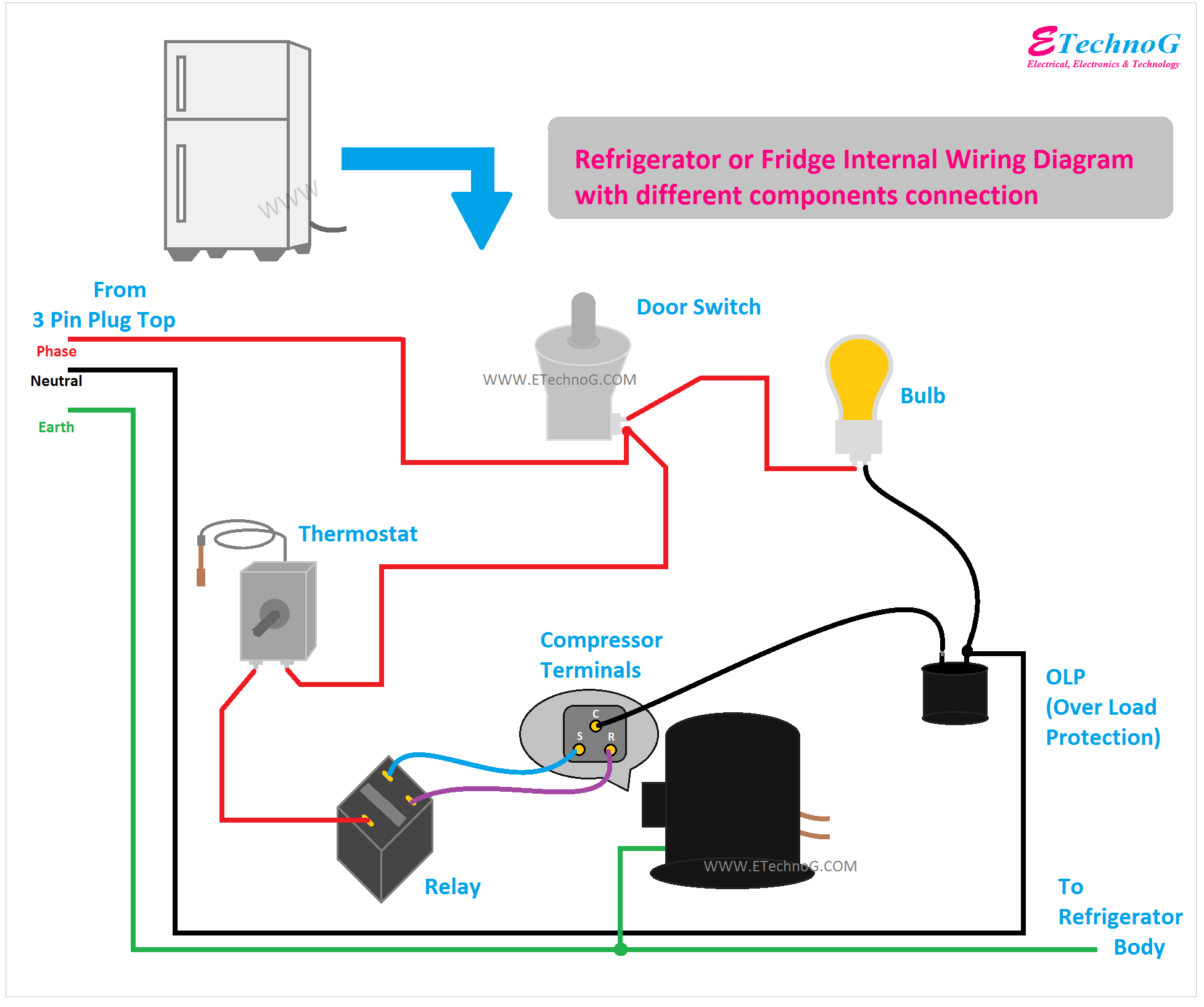
A wiring diagram of a refrigerator represents the electrical connections and components within the appliance. It provides a visual guide to troubleshoot issues, understand its functionality, and ensure proper installation and maintenance.
The wiring diagram is crucial for understanding the refrigerator’s electrical system and ensuring its safe operation. It helps diagnose electrical problems, such as a malfunctioning compressor or faulty thermostat, by tracing the electrical flow and identifying potential points of failure.
Historically, wiring diagrams were drawn by hand, but advances in technology have led to computer-aided design (CAD) software, resulting in more precise and detailed representations. The development of standardized symbols and color coding further enhances clarity and consistency in these diagrams.
A wiring diagram of a refrigerator is a detailed representation of the electrical connections and components within the appliance. It serves as a crucial guide for understanding its functionality, troubleshooting issues, and ensuring proper installation and maintenance. Here are nine key aspects of a wiring diagram of a refrigerator:
- Components: It identifies all the electrical components in the refrigerator, including the compressor, thermostat, fan motor, and defrost heater.
- Connections: It shows how these components are electrically connected to each other, forming a complete circuit.
- Power source: It indicates the power source for the refrigerator, whether it’s a standard electrical outlet or a dedicated circuit.
- Grounding: It specifies the grounding connections to ensure the safe operation of the refrigerator and prevent electrical shocks.
- Wiring colors: It uses standardized color coding for the wires, making it easier to identify and trace connections.
- Symbols: It employs universally recognized electrical symbols to represent different components and connections.
- Troubleshooting: It assists in troubleshooting electrical problems by providing a visual representation of the system.
- Installation: It guides the proper installation of the refrigerator, ensuring that all electrical connections are made correctly.
- Maintenance: It serves as a reference for maintenance tasks, such as replacing faulty components or checking connections.
These aspects collectively provide a comprehensive understanding of the electrical system of a refrigerator. By studying the wiring diagram, technicians can diagnose problems, perform repairs, and ensure the safe and efficient operation of the appliance.
Components
Understanding the components of a refrigerator wiring diagram is essential for troubleshooting and repair. The diagram identifies all the electrical components in the refrigerator, including the compressor, thermostat, fan motor, and defrost heater. Each of these components plays a vital role in the operation of the refrigerator, and a thorough understanding of their function is crucial for effective maintenance.
- Compressor: The compressor is the heart of the refrigerator, responsible for circulating the refrigerant throughout the system. It compresses the refrigerant gas, increasing its pressure and temperature, and then pumps it into the condenser coils.
- Thermostat: The thermostat controls the temperature inside the refrigerator by regulating the operation of the compressor. It senses the temperature within the refrigerator and turns the compressor on or off as needed to maintain the desired temperature.
- Fan motor: The fan motor circulates air within the refrigerator, ensuring an even distribution of cold air throughout the compartments. It helps maintain a consistent temperature and prevents warm air from entering the refrigerator.
- Defrost heater: The defrost heater prevents ice buildup on the evaporator coils. It periodically turns on to melt any accumulated ice, ensuring efficient heat transfer and proper cooling performance.
By understanding the function and location of these components, technicians can quickly identify potential problems and perform necessary repairs. The wiring diagram serves as a valuable tool for troubleshooting and maintaining the refrigerator, ensuring its optimal performance and extending its lifespan.
Connections
In the context of a wiring diagram of a refrigerator, the connections between components are crucial for understanding the flow of electricity and ensuring proper functionality. These connections establish a complete circuit, allowing electrical current to power the various components and perform the intended cooling operations.
- Power Supply: The wiring diagram indicates the connection to the main power supply, typically a household electrical outlet. This connection provides the necessary voltage and amperage to power the refrigerator.
- Compressor: The compressor is the heart of the refrigeration system. The wiring diagram shows the electrical connections to the compressor motor, ensuring it receives power to compress the refrigerant and circulate it throughout the system.
- Thermostat: The thermostat controls the temperature inside the refrigerator. The wiring diagram illustrates the connections between the thermostat and the compressor, allowing the thermostat to regulate the compressor’s operation and maintain the desired temperature.
- Defrost System: The defrost system prevents ice buildup on the evaporator coils. The wiring diagram includes the connections to the defrost timer and heating element, which periodically activate to melt accumulated ice.
Understanding the connections between these components is essential for troubleshooting and repair. By tracing the electrical flow through the wiring diagram, technicians can identify faulty connections, defective components, or other issues that may affect the refrigerator’s performance. Accurate wiring ensures a complete and safe electrical circuit, preventing potential hazards and ensuring optimal cooling efficiency.
Power source
In the context of a wiring diagram of a refrigerator, specifying the power source is crucial for understanding the electrical requirements and ensuring safe operation. It determines the type of electrical connection needed and helps avoid potential hazards related to overloading or insufficient power supply.
- Electrical Outlet: Most refrigerators are designed to be plugged into a standard electrical outlet, which typically provides 110-120 volts of alternating current (AC). The wiring diagram specifies the plug type and amperage rating required for the outlet.
- Dedicated Circuit: In some cases, particularly for larger or more powerful refrigerators, a dedicated electrical circuit may be recommended. This involves running a separate circuit from the main electrical panel to the refrigerator, providing it with its own dedicated power source. Dedicated circuits help prevent overloading and ensure a reliable power supply for the refrigerator.
- Voltage and Amperage: The wiring diagram indicates the specific voltage and amperage requirements for the refrigerator. Voltage refers to the electrical potential difference, while amperage measures the current flow. Understanding these specifications is essential for selecting the correct power source and ensuring compatibility with the refrigerator’s electrical system.
- Grounding: The wiring diagram also specifies the grounding requirements for the refrigerator. Proper grounding provides a safe path for electrical current to flow in the event of a fault, protecting users from electrical shocks.
By specifying the power source, the wiring diagram ensures that the refrigerator is connected to a compatible and safe electrical supply. It guides electricians and homeowners in selecting the appropriate outlet or circuit, ensuring reliable operation and minimizing the risk of electrical hazards.
Grounding
Grounding is an essential safety measure in any electrical system. In the context of a refrigerator’s wiring diagram, the grounding specifications play a crucial role in protecting both the appliance and its users from electrical hazards.
- Ground Wire: The wiring diagram identifies the ground wire, which is typically green or bare copper. This wire provides a low-resistance path for electrical current to flow to the ground in the event of a fault.
- Grounding Terminal: The refrigerator’s wiring diagram specifies the location of the grounding terminal, which is usually a metal lug or screw located on the frame or chassis of the appliance. The ground wire must be securely connected to this terminal.
- Ground Fault Circuit Interrupter (GFCI): Some refrigerators may be equipped with a GFCI, which is a safety device that monitors the electrical current flowing through the ground wire. If the GFCI detects an imbalance in the current, it quickly interrupts the power supply, preventing electrical shocks.
- Importance of Grounding: Proper grounding ensures that any stray electrical current is safely diverted away from the refrigerator’s metal components and into the grounding system of the building. This prevents the buildup of dangerous voltages on the refrigerator’s frame, which could lead to electrical shocks or fires.
By understanding and following the grounding specifications in the refrigerator’s wiring diagram, electricians and homeowners can ensure that the appliance is properly grounded, reducing the risk of electrical hazards and ensuring the safe operation of the refrigerator.
Wiring Colors
Within the intricate network of a refrigerator’s electrical system, standardized wire color coding plays a vital role in simplifying the identification and tracing of connections. This color-coded system forms a critical component of the wiring diagram, providing a clear visual guide for technicians and homeowners alike.
The primary function of wire color coding is to distinguish between different types of electrical connections. For instance, in a refrigerator’s wiring diagram, black or brown wires typically denote “hot” wires carrying live current, while white or gray wires represent “neutral” wires completing the circuit. Green or bare copper wires are reserved for grounding, ensuring the safe dissipation of stray electrical currents.
The importance of standardized wire color coding cannot be overstated. It streamlines the troubleshooting process, reducing the time and effort required to locate and repair electrical faults. By following the color-coded wires, technicians can quickly identify the source of a problem, whether it’s a loose connection, a faulty component, or a more complex issue.
Furthermore, color coding enhances safety during installation and maintenance. Electricians can confidently connect wires of the same color, knowing that they belong to the same circuit or function. This minimizes the risk of accidental misconnections, which could lead to electrical hazards.
In summary, the standardized color coding of wires is an indispensable aspect of a refrigerator’s wiring diagram, enabling efficient identification and tracing of connections. It simplifies troubleshooting, enhances safety, and serves as a valuable tool for both professionals and homeowners maintaining and repairing refrigerators.
Symbols
Within the intricate network of a refrigerator’s electrical system, universally recognized electrical symbols form the visual language that simplifies the understanding of complex connections and components. This standardized iconography provides a clear and concise representation of the refrigerator’s electrical layout, enabling technicians and homeowners to navigate the wiring diagram effectively.
- Graphical Representation: Electrical symbols are graphical representations of electrical components, such as resistors, capacitors, transistors, and switches. These symbols convey the function and behavior of each component, allowing users to quickly identify and understand their role in the circuit.
- Standardized Language: Electrical symbols adhere to international standards, ensuring consistency across different wiring diagrams and documentation. This standardized language facilitates communication among professionals and reduces the risk of misinterpretation, enhancing safety and accuracy.
- Simplified Complexity: Electrical symbols simplify the complexity of a refrigerator’s wiring diagram. By representing components with concise symbols, the diagram becomes easier to read and comprehend, allowing users to focus on the overall functionality and relationships between different components.
In summary, the use of universally recognized electrical symbols in the wiring diagram of a refrigerator serves as a powerful tool for understanding and troubleshooting the appliance’s electrical system. These symbols provide a simplified and standardized visual language, enabling users to navigate the complexities of the circuit effectively, ensuring safe and efficient maintenance and repair.
Troubleshooting
When electrical issues arise within a refrigerator, the wiring diagram serves as an invaluable tool for troubleshooting. It provides a visual representation of the entire electrical system, enabling technicians and homeowners to trace the flow of electricity and identify potential faults.
By studying the wiring diagram, technicians can systematically check each component and connection, isolating the source of the problem. For instance, if the refrigerator is not cooling properly, the wiring diagram can help identify whether the issue lies with the compressor, thermostat, or a faulty wire connection.
Real-life examples further illustrate the critical role of troubleshooting in conjunction with the wiring diagram. Consider a scenario where the refrigerator’s interior lights are not functioning. By referring to the wiring diagram, a technician can determine the circuit responsible for powering the lights and trace the connections to identify any loose wires, blown fuses, or faulty switches.
The practical applications of this understanding extend beyond troubleshooting. The wiring diagram also serves as a guide for repair and maintenance tasks. By understanding the electrical connections and component locations, technicians can efficiently replace faulty parts, rewire damaged sections, and ensure the refrigerator’s safe and optimal operation.
In summary, the wiring diagram of a refrigerator, coupled with the ability to troubleshoot electrical problems, provides a comprehensive tool for maintaining and repairing this essential household appliance. It empowers individuals with the knowledge to diagnose and resolve common electrical issues, ensuring the continued functionality and efficiency of their refrigerators.
Installation
The proper installation of a refrigerator is critical to ensure both its optimal performance and electrical safety. This is where the wiring diagram plays a pivotal role. It provides detailed instructions on how to make the electrical connections correctly, ensuring that the refrigerator operates as intended and meets all safety standards.
Real-life examples underscore the importance of following the wiring diagram during installation. Incorrect wiring can lead to various problems, ranging from minor malfunctions to severe electrical hazards. For instance, improper grounding can result in electrical shocks or even fires. By carefully following the wiring diagram, installers can avoid such risks and ensure the safe and efficient operation of the refrigerator.
The practical applications of this understanding extend beyond avoiding electrical hazards. Proper installation, guided by the wiring diagram, also contributes to the refrigerator’s energy efficiency and longevity. Correctly connecting the electrical components ensures that the refrigerator operates at its optimal level, consuming less energy and extending its lifespan.
In summary, the wiring diagram serves as an indispensable guide for the proper installation of a refrigerator. It provides detailed instructions on making the electrical connections correctly, ensuring the refrigerator’s safe operation, energy efficiency, and longevity. Understanding and adhering to the wiring diagram is essential for anyone involved in the installation process, from professional electricians to homeowners.
Maintenance
The wiring diagram of a refrigerator serves as an essential reference tool for maintenance tasks, empowering individuals to maintain the appliance’s optimal performance and longevity. It provides clear instructions on how to troubleshoot common issues, replace faulty components, and check electrical connections, ensuring the refrigerator operates safely and efficiently.
Real-life examples demonstrate the critical importance of utilizing the wiring diagram during maintenance. For instance, when a refrigerator is experiencing cooling problems, the wiring diagram guides technicians in identifying the faulty component, whether it’s a malfunctioning compressor or a faulty thermostat. By following the diagram, technicians can quickly diagnose the issue and replace the necessary components, restoring the refrigerator’s functionality.
The practical applications of this understanding extend beyond troubleshooting. The wiring diagram serves as a comprehensive guide for routine maintenance tasks, such as cleaning condenser coils or defrosting the evaporator. By understanding the electrical connections and component locations, homeowners can perform these tasks confidently, ensuring the refrigerator operates at its peak efficiency and extends its lifespan.
In summary, the wiring diagram is an indispensable tool for maintaining a refrigerator. It provides detailed instructions for troubleshooting, replacing components, and performing routine maintenance tasks. Understanding and adhering to the wiring diagram empowers individuals to keep their refrigerators operating safely, efficiently, and for many years to come.


Related Posts


