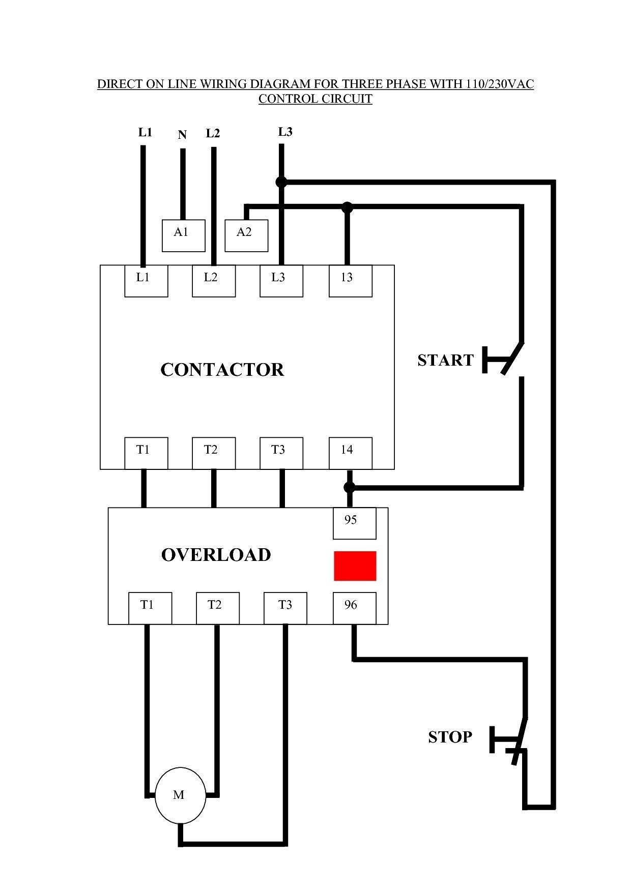
A wiring diagram for an AC contactor is a detailed plan that shows how to connect the contactor to an electrical circuit. It includes symbols for the contactor, the electrical components it connects to, and the wires that connect them. For example, a wiring diagram for a contactor in an air conditioning system might show how to connect the contactor to the compressor, the fan, and the thermostat.
Wiring diagrams are important because they help to ensure that electrical circuits are connected correctly and safely. They can also be helpful for troubleshooting problems with electrical circuits. A key historical development in the field of wiring diagrams was the invention of the schematic diagram in the late 19th century. Schematic diagrams are simplified versions of wiring diagrams that use symbols to represent electrical components and their connections.
This article will provide a comprehensive overview of wiring diagrams for AC contactors. It will cover the different types of wiring diagrams, the symbols used in wiring diagrams, and the steps involved in creating a wiring diagram. The article will also provide some tips for troubleshooting problems with wiring diagrams.
Wiring diagrams for AC contactors are essential for ensuring that electrical circuits are connected correctly and safely. They can also be helpful for troubleshooting problems with electrical circuits. The following are nine key aspects of wiring diagrams for AC contactors:
- Symbols
- Components
- Connections
- Layout
- Accuracy
- Clarity
- Completeness
- Safety
- Standards
Symbols are used to represent electrical components and their connections in wiring diagrams. It is important to use the correct symbols to ensure that the wiring diagram is accurate and easy to understand. The components that are included in a wiring diagram will vary depending on the specific circuit. However, some of the most common components include contactors, starters, and transformers. The connections between the components are shown by lines. It is important to ensure that the connections are accurate and complete. The layout of a wiring diagram is also important. The diagram should be easy to read and understand. The accuracy of a wiring diagram is essential. An inaccurate wiring diagram can lead to electrical problems. Clarity is also important. The wiring diagram should be clear and concise. Completeness is another important aspect of wiring diagrams. The diagram should include all of the necessary information to ensure that the electrical circuit is connected correctly and safely. Safety is also a key consideration when creating wiring diagrams. The diagram should be designed to ensure that the electrical circuit is safe to operate. Standards are also important when creating wiring diagrams. The diagram should conform to the relevant electrical codes and standards.
Symbols
Symbols are an essential part of wiring diagrams for AC contactors. They are used to represent electrical components and their connections in a way that is easy to understand. Without symbols, wiring diagrams would be much more difficult to read and interpret. In fact, it would be nearly impossible to create a wiring diagram without using symbols.
Symbols are used for a variety of different electrical components, including contactors, starters, and transformers. Each symbol is unique and represents a specific component. This makes it easy to identify the components in a wiring diagram and to understand how they are connected. For example, the symbol for a contactor is a rectangle with two lines coming out of the top and two lines coming out of the bottom. The lines represent the terminals of the contactor. The symbol for a starter is a circle with two lines coming out of the top and two lines coming out of the bottom. The lines represent the terminals of the starter.
Symbols are not only used to represent electrical components, but also to represent the connections between them. For example, a solid line represents a direct connection between two components. A dashed line represents an indirect connection between two components. This makes it easy to see how the components in a wiring diagram are connected.
Symbols are a critical component of wiring diagrams for AC contactors. They make it possible to create wiring diagrams that are easy to read and interpret. This is essential for ensuring that electrical circuits are connected correctly and safely.
Components
Components play a critical role in wiring diagrams for AC contactors. They represent the various electrical components that are used to create the circuit. Understanding the different components and their functions is essential for creating accurate and reliable wiring diagrams.
-
Contactors
Contactors are the main switching devices in AC contactor circuits. They are used to control the flow of electricity to the load. Contactors have two main sets of contacts: power contacts and auxiliary contacts. The power contacts are used to switch the load current, while the auxiliary contacts are used to control other devices, such as pilot lights or interlocks.
-
Starters
Starters are used to start AC motors. They provide a reduced voltage to the motor during startup, which helps to reduce the inrush current. Starters can be either manual or automatic. Manual starters are operated by a switch, while automatic starters are operated by a control circuit.
-
Transformers
Transformers are used to change the voltage of an AC circuit. They can be used to step up the voltage (increase the voltage) or step down the voltage (decrease the voltage). Transformers are used in a variety of applications, such as power distribution and motor control.
-
Overload relays
Overload relays are used to protect motors from damage due to overloads. They sense the current flowing through the motor and trip if the current exceeds a predetermined value. Overload relays can be either thermal or magnetic.
These are just a few of the many components that can be used in wiring diagrams for AC contactors. By understanding the different components and their functions, you can create accurate and reliable wiring diagrams that will help to ensure the safe and efficient operation of your electrical circuits.
Connections
Connections are a critical aspect of wiring diagrams for AC contactors. They represent the electrical pathways between the various components in the circuit. Understanding the different types of connections and how they are used is essential for creating accurate and reliable wiring diagrams.
-
Power Connections
Power connections are used to connect the contactor to the power source and the load. The power source is typically a three-phase AC supply, and the load is typically a motor or other electrical device.
-
Control Connections
Control connections are used to connect the contactor to the control circuit. The control circuit is typically a low-voltage circuit that is used to control the operation of the contactor.
-
Interlock Connections
Interlock connections are used to connect the contactor to other devices in the circuit. For example, interlock connections can be used to prevent the contactor from operating if another device is not in the correct position.
-
Ground Connections
Ground connections are used to connect the contactor to the electrical ground. The electrical ground is a reference point that is used to ensure that the circuit is safe to operate.
Connections are an essential part of wiring diagrams for AC contactors. By understanding the different types of connections and how they are used, you can create accurate and reliable wiring diagrams that will help to ensure the safe and efficient operation of your electrical circuits.
Layout
The layout of a wiring diagram for an AC contactor is an important factor that can affect the readability, understandability, and accuracy of the diagram. A well-laid-out diagram will be easy to follow and will help to prevent errors in wiring the contactor. Conversely, a poorly laid-out diagram can be difficult to understand and may lead to wiring errors.
-
Clarity
The layout of a wiring diagram should be clear and easy to understand. The symbols and connections should be arranged in a logical way that makes it easy to trace the flow of current through the circuit. The use of color can also help to improve the clarity of a wiring diagram.
-
Accuracy
The layout of a wiring diagram must be accurate. The symbols and connections must represent the actual wiring of the contactor. Any errors in the layout of the diagram could lead to errors in wiring the contactor.
-
Completeness
The layout of a wiring diagram should be complete. The diagram should include all of the necessary information to wire the contactor correctly. This includes the symbols for all of the components in the circuit, the connections between the components, and the wire sizes.
-
Safety
The layout of a wiring diagram should be safe. The diagram should be designed in a way that minimizes the risk of electrical shock or other hazards.
By following these guidelines, you can create wiring diagrams for AC contactors that are clear, accurate, complete, and safe.
Accuracy
Accuracy is of utmost importance in the context of wiring diagrams for AC contactors. These diagrams provide a visual representation of the electrical connections within an AC contactor, and any inaccuracies can lead to serious safety hazards or equipment damage. Therefore, it is crucial that these diagrams are meticulously checked for accuracy before they are used.
-
Component Accuracy
The symbols and components used in the wiring diagram must accurately reflect the actual components used in the AC contactor. This includes ensuring that the correct symbols are used, the components are properly labeled, and the quantities of each component are correct.
-
Connection Accuracy
The wiring diagram must accurately depict the connections between the various components in the AC contactor. This includes ensuring that the wires are correctly sized and rated, the connections are properly made, and the wire colors are consistent with industry standards.
-
Label Accuracy
The wiring diagram must include accurate and comprehensive labels for all of the components and connections. These labels should clearly identify each component and connection, and they should be consistent with the labels used on the actual AC contactor.
-
Testing and Verification
Once the wiring diagram is complete, it is crucial to test and verify its accuracy. This can be done by comparing the diagram to the actual AC contactor, by performing continuity tests, or by using other methods to ensure that the diagram accurately represents the electrical connections.
By ensuring accuracy in all aspects of the wiring diagram, engineers and technicians can ensure the safe and reliable operation of AC contactors. Inaccurate wiring diagrams can lead to a variety of problems, including electrical fires, equipment damage, and even personal injury. Therefore, it is essential to take the time to carefully check and verify the accuracy of wiring diagrams before they are used.
Clarity
Clarity is a crucial aspect of wiring diagrams for AC contactors. A clear diagram is easy to understand and follow, which is essential for ensuring that the contactor is wired correctly and safely. There are several key facets of clarity in wiring diagrams:
-
Symbol Clarity
The symbols used in a wiring diagram should be clear and easy to identify. Standard symbols, compliant with industry practices, should be used throughout the diagram to ensure uniformity and avoid confusion.
-
Label Clarity
All components and connections in the wiring diagram should be clearly labeled. The labels should be concise, accurate, and consistent throughout the diagram. Clear labeling makes it easy to identify and locate specific components and connections.
-
Layout Clarity
The layout of the wiring diagram should be clear and logical. The components and connections should be arranged in a way that makes it easy to trace the flow of current through the contactor. A well-organized layout enhances readability and reduces the risk of misinterpreting the diagram.
-
Color Clarity
Color can be used to improve the clarity of a wiring diagram. Different colors can be used to represent different types of components or connections. This can make it easier to identify and distinguish between different parts of the circuit.
By incorporating these facets of clarity into wiring diagrams for AC contactors, engineers and technicians can ensure that the diagrams are easy to understand and follow. This, in turn, helps to reduce the risk of errors in wiring the contactor, which can lead to safety hazards or equipment damage.
Completeness
Completeness is a crucial aspect of wiring diagrams for AC contactors. A complete wiring diagram includes all the necessary information to ensure that the contactor is wired correctly and safely. This includes information on the contactor’s components, connections, and operating parameters. Without complete information, it is difficult to ensure that the contactor is wired correctly, which can lead to safety hazards or equipment damage.
One of the most important aspects of a complete wiring diagram is that it includes all of the necessary components. This includes the contactor itself, as well as any other components that are necessary for the contactor to operate properly, such as overload relays, timers, and interlocks. In addition to including all of the necessary components, a complete wiring diagram also includes all of the necessary connections between the components. These connections must be accurate and complete in order to ensure that the contactor operates correctly.
In addition to including all of the necessary components and connections, a complete wiring diagram also includes all of the necessary operating parameters. This information includes the contactor’s voltage rating, current rating, and operating frequency. This information is necessary to ensure that the contactor is used within its safe operating limits.
Complete wiring diagrams are essential for ensuring the safe and reliable operation of AC contactors. By providing all of the necessary information, complete wiring diagrams help to prevent errors in wiring the contactor, which can lead to safety hazards or equipment damage.
Safety
In the realm of wiring diagrams for AC contactors, safety plays a paramount role. It encompasses various aspects that ensure the safe and reliable operation of electrical circuits. A comprehensive understanding of these safety considerations is crucial to prevent potential hazards and maintain a secure electrical environment.
-
Component Compatibility
Wiring diagrams must ensure compatibility between the contactor and the connected components. Mismatched components can lead to overloads, short circuits, or equipment damage. Proper selection of components based on their voltage, current, and power ratings is essential for safe operation.
-
Proper Grounding
Effective grounding is vital for safety. Wiring diagrams must clearly indicate grounding connections to prevent electrical shocks and protect equipment. Adequate grounding ensures a safe path for fault currents to dissipate, minimizing the risk of electrical accidents.
-
Clear Labeling
. . .
-
Compliance with Codes
Wiring diagrams must adhere to established electrical codes and standards. These codes specify requirements for safe electrical installations, including wire sizes, insulation types, and circuit protection measures. Compliance with codes ensures that electrical circuits meet minimum safety criteria and minimize the risk of electrical fires or accidents.
Understanding and implementing these safety considerations in wiring diagrams for AC contactors is crucial for maintaining a safe and efficient electrical environment. By adhering to these principles, engineers and technicians can ensure the proper operation of electrical systems, minimize the risk of accidents, and protect personnel and equipment from electrical hazards.
Standards
In the realm of “Wiring Diagram For Ac Contactor”, “Standards” play a critical role in ensuring safety, reliability, and consistency. These standards provide guidelines and specifications for the design, installation, and maintenance of electrical systems, including AC contactors. By adhering to established standards, engineers and technicians can minimize risks, enhance performance, and ensure the proper functioning of AC contactors.
-
Electrical Codes
Electrical codes are a fundamental aspect of standards for wiring diagrams of AC contactors. These codes specify requirements for the installation and maintenance of electrical systems, including wire sizes, insulation types, and circuit protection measures. Compliance with electrical codes is essential for ensuring the safety and reliability of electrical circuits.
-
Industry Best Practices
Industry best practices represent widely accepted guidelines and recommendations for the design and implementation of wiring diagrams for AC contactors. These best practices cover various aspects, such as component selection, connection methods, and documentation procedures. Following industry best practices helps to ensure that wiring diagrams are clear, accurate, and consistent.
-
Manufacturer Specifications
Manufacturer specifications provide specific guidelines for the installation and operation of AC contactors. These specifications include information on contactor ratings, terminal connections, and operating conditions. Adhering to manufacturer specifications is essential for ensuring that AC contactors are used safely and within their intended limits.
-
International Standards
International standards, such as those developed by the International Electrotechnical Commission (IEC), provide a global framework for the design and implementation of electrical systems. These standards aim to harmonize electrical practices across countries, ensuring safety and interoperability. Compliance with international standards allows for the exchange of electrical equipment and expertise on a global scale.
By incorporating these standards into wiring diagrams for AC contactors, engineers and technicians can ensure the safety, reliability, and efficiency of electrical systems. Standards provide a common language and a set of best practices that facilitate collaboration, prevent errors, and promote the safe operation of AC contactors.


Related Posts


