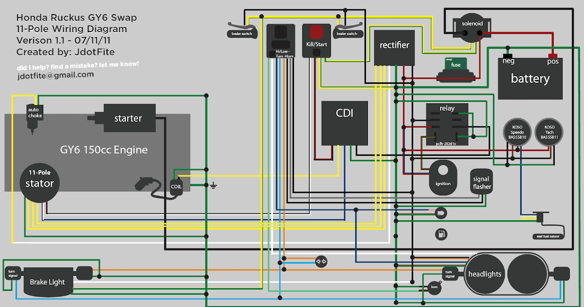
A GY6 wiring schematic is a diagram that illustrates the electrical connections within a GY6 engine, a type of gasoline engine commonly found in scooters and other small vehicles. It provides a visual representation of the electrical system, including the placement and function of components such as the battery, ignition coil, and starter motor. An example of a GY6 wiring schematic can be found in the owner’s manual of a scooter equipped with this engine.
Wiring schematics are crucial for understanding and maintaining electrical systems. They enable technicians to trace electrical circuits, identify faulty components, and perform repairs effectively. A significant historical development in the field of wiring schematics was the introduction of computer-aided design (CAD) software, which revolutionized the accuracy and efficiency of creating and modifying electrical diagrams.
This article delves into the components, operation, and troubleshooting techniques related to GY6 wiring schematics. It aims to provide a comprehensive understanding of this essential aspect of small engine maintenance and repair.
Understanding the essential aspects of a GY6 wiring schematic is crucial for maintaining and repairing small engines effectively. These aspects encompass various dimensions related to the schematic, including its components, operation, and troubleshooting techniques.
- Components: Battery, ignition coil, starter motor, wires, connectors
- Operation: Electrical circuits, power flow, ignition timing
- Troubleshooting: Electrical faults, diagnostic techniques, repair procedures
- Maintenance: Inspection, cleaning, replacement of components
- Safety: Electrical hazards, precautions, proper handling
- Tools: Multimeter, wiring crimper, soldering iron
- Resources: Wiring diagrams, repair manuals, online forums
- Skills: Electrical knowledge, mechanical aptitude, attention to detail
These aspects are interconnected and play vital roles in ensuring the proper functioning of a GY6 engine. By understanding the components, operation, and troubleshooting techniques of a GY6 wiring schematic, technicians can diagnose and resolve electrical issues efficiently, ensuring optimal engine performance and longevity.
Components
In the context of a GY6 wiring schematic, the componentsbattery, ignition coil, starter motor, wires, and connectorsplay critical roles in the proper functioning of the electrical system. The wiring schematic serves as a visual representation of these components and their interconnections, providing a comprehensive overview of the electrical system’s design and operation.
The battery serves as the primary power source for the electrical system, supplying electricity to the ignition coil, starter motor, and other electrical components. The ignition coil generates high-voltage pulses that are sent to the spark plugs, igniting the air-fuel mixture in the engine’s cylinders. The starter motor engages with the engine’s flywheel to initiate engine rotation during startup. Wires facilitate the flow of electricity between components, while connectors ensure secure and reliable electrical connections.
Understanding the relationship between these components and the GY6 wiring schematic is essential for troubleshooting and repairing electrical faults. By analyzing the schematic, technicians can trace electrical circuits, identify faulty components, and determine appropriate repair procedures. For example, if the engine fails to start, the technician can consult the wiring schematic to verify if power is reaching the starter motor and ignition coil. This systematic approach enables efficient and accurate electrical system diagnostics and repairs.
In summary, the componentsbattery, ignition coil, starter motor, wires, and connectorsare indispensable elements of a GY6 wiring schematic. Their proper functioning ensures reliable engine operation and performance. By understanding the interconnections and functions of these components within the electrical system, technicians can effectively troubleshoot and repair electrical issues, ensuring optimal engine performance and longevity.
Operation
The operation of a GY6 engine’s electrical system encompasses a complex interplay of electrical circuits, power flow, and ignition timing. Understanding these aspects is essential for diagnosing and resolving electrical issues, ensuring optimal engine performance and longevity. The GY6 wiring schematic provides a visual representation of these electrical components and their interconnections.
- Circuit Design: The wiring schematic illustrates the layout of electrical circuits, including the connections between the battery, ignition coil, starter motor, and other components. This enables technicians to trace the flow of electricity and identify potential points of failure.
- Power Distribution: The schematic shows how power is distributed from the battery to various electrical components. This information is crucial for ensuring that components receive the appropriate voltage and amperage for proper operation.
- Ignition Timing: The wiring schematic provides insights into the timing of the ignition system. This includes the sequence of events that occur when the ignition coil generates a spark and the spark plugs ignite the air-fuel mixture in the engine’s cylinders.
- Grounding: The schematic indicates the grounding points in the electrical system. Proper grounding is essential for completing electrical circuits and preventing electrical malfunctions.
By analyzing the operation of electrical circuits, power flow, and ignition timing in relation to the GY6 wiring schematic, technicians can gain a comprehensive understanding of the electrical system’s design and functionality. This knowledge empowers them to troubleshoot and repair electrical faults efficiently, ensuring reliable engine performance and longevity.
Troubleshooting
Troubleshooting electrical faults in a GY6 engine requires a systematic approach that involves analyzing the electrical system’s components, operation, and wiring schematic. The GY6 wiring schematic provides a visual representation of the electrical components and their interconnections, enabling technicians to identify potential points of failure and trace the flow of electricity. By understanding the wiring schematic, technicians can efficiently troubleshoot electrical faults and determine appropriate repair procedures.
For example, if the engine fails to start, the technician can consult the wiring schematic to verify if power is reaching the starter motor and ignition coil. This systematic approach ensures accurate electrical system diagnostics and repairs, minimizing downtime and maximizing engine performance. Furthermore, the wiring schematic provides insights into the sequence of events that occur during ignition timing, which is crucial for troubleshooting ignition-related faults.
In summary, troubleshooting electrical faults in a GY6 engine is inextricably linked to the GY6 wiring schematic. By understanding the electrical system’s components, operation, and wiring schematic, technicians can effectively diagnose and repair electrical faults, ensuring optimal engine performance and longevity. This knowledge is essential for maintaining and repairing GY6 engines in various applications, such as scooters, ATVs, and other small engine vehicles.
Maintenance
Within the context of a GY6 wiring schematic, maintenance encompasses a range of activities aimed at ensuring the proper functioning and longevity of the electrical system. These activities include regular inspection, cleaning, and replacement of components.
- Battery Inspection and Cleaning: The battery is a critical component that provides power to the electrical system. Regular inspection involves checking for corrosion on the terminals and cleaning them to ensure good electrical contact. This helps prevent power loss and starting problems.
- Connector Inspection and Cleaning: Connectors play a vital role in establishing electrical connections between components. Loose or dirty connectors can lead to intermittent electrical faults. Inspecting and cleaning connectors ensures proper electrical contact and prevents connection issues.
- Wire Inspection and Replacement: Wires carry electrical current throughout the system. Inspecting wires for damage, such as cuts or fraying, is crucial for preventing short circuits or electrical failures. Damaged wires should be replaced promptly to maintain electrical integrity.
- Ignition Coil Inspection and Replacement: The ignition coil generates the high-voltage spark necessary for engine ignition. Regular inspection involves checking for cracks or damage to the coil body or terminals. A faulty ignition coil can lead to ignition problems and poor engine performance.
Regular maintenance, including inspection, cleaning, and replacement of components, is essential for the reliability and longevity of the GY6 electrical system. By adhering to a proactive maintenance schedule, technicians can identify and address potential electrical issues early on, preventing costly repairs and ensuring optimal engine performance.
Safety
Within the context of Gy6 Wiring Schematic, safety plays a critical role in ensuring the well-being of technicians and the prevention of electrical hazards. Understanding and adhering to proper safety precautions and handling techniques are essential for working with electrical systems.
- Electrical Shock Hazards: Electrical shock occurs when a person comes into contact with a live electrical circuit. The GY6 Wiring Schematic provides insights into the location of live wires and components, enabling technicians to identify potential shock hazards and take appropriate precautions, such as wearing insulated gloves and using proper tools.
- Short Circuit Risks: A short circuit occurs when an unintended electrical path is created between two points, causing excessive current flow. The Wiring Schematic helps technicians identify potential short circuit points, such as loose connections or damaged wires. Proper handling techniques, such as using insulated tools and avoiding contact with bare wires, minimize the risk of short circuits.
- Fire Hazards: Electrical faults can lead to fires, especially if flammable materials are present. The Wiring Schematic provides information on the location of critical components, such as the battery and ignition coil, helping technicians identify potential fire hazards and take preventive measures, such as keeping the electrical system clean and free of debris.
- Battery Safety: The battery is a vital component of the electrical system, but it also poses potential hazards, such as acid leaks and explosions. The Wiring Schematic indicates the location of the battery and provides guidelines for safe handling, such as wearing protective gear and avoiding contact with battery terminals when the engine is running.
By understanding the safety aspects outlined in the Gy6 Wiring Schematic and adhering to proper precautions and handling techniques, technicians can effectively mitigate electrical hazards, ensuring a safe working environment and preventing damage to the electrical system.
Tools
Within the context of GY6 wiring schematics, the utilization of specific tools, namely a multimeter, wiring crimper, and soldering iron, plays a critical role in ensuring the proper functioning, maintenance, and repair of electrical systems. These tools empower technicians with the ability to diagnose electrical faults, create secure electrical connections, and modify or repair electrical components.
The multimeter serves as a versatile diagnostic tool, enabling technicians to measure voltage, current, and resistance within the electrical system. By analyzing these measurements and comparing them to the specifications outlined in the wiring schematic, technicians can pinpoint the source of electrical faults, such as short circuits, open circuits, or faulty components. This information guides targeted repairs, minimizing downtime and maximizing system reliability.
The wiring crimper is an essential tool for creating secure and reliable electrical connections. It ensures that wires are properly crimped to terminals or connectors, preventing loose connections that could lead to intermittent electrical faults or even electrical fires. The crimper’s precise crimping action ensures a strong and durable connection, meeting the specifications outlined in the wiring schematic.
The soldering iron plays a crucial role in modifying or repairing electrical components. It allows technicians to solder wires to terminals or circuit boards, creating permanent and reliable electrical connections. When performed correctly, soldering ensures a strong bond between the metal surfaces, preventing high-resistance connections that could lead to voltage drops or electrical failures. The wiring schematic provides guidance on the appropriate soldering techniques and the specific components that require soldering.
In summary, the multimeter, wiring crimper, and soldering iron are indispensable tools for working with GY6 wiring schematics. They empower technicians to diagnose electrical faults, create secure electrical connections, and modify or repair electrical components. Understanding the functions and applications of these tools is essential for effective electrical system maintenance and repair, ensuring optimal performance and longevity of the GY6 engine.
Resources
Within the context of GY6 wiring schematics, a multitude of resources, including wiring diagrams, repair manuals, and online forums, play a pivotal role in supporting the effective understanding, maintenance, and repair of electrical systems. These resources provide invaluable information, guidance, and support to technicians and enthusiasts alike.
Wiring diagrams serve as visual representations of electrical circuits, outlining the connections between components and providing insights into the flow of electricity. Repair manuals offer step-by-step instructions, troubleshooting tips, and technical specifications, empowering individuals to perform repairs with confidence. Online forums foster a community of experts and enthusiasts who share knowledge, experiences, and solutions to common electrical issues.
The connection between these resources and GY6 wiring schematics is symbiotic. Wiring diagrams provide the foundation for understanding the electrical system, but repair manuals and online forums offer practical guidance and support, enabling technicians to diagnose faults, perform repairs, and modify electrical systems effectively. Real-life examples of this relationship abound, with online forums serving as platforms where users share their experiences, troubleshoot problems, and contribute to a collective knowledge base.
The practical applications of this understanding are far-reaching. By leveraging wiring diagrams, repair manuals, and online forums, technicians can:
- Quickly identify and resolve electrical faults, minimizing downtime and maximizing system performance.
- Perform complex repairs with confidence, guided by step-by-step instructions and technical specifications.
- Access a wealth of knowledge and support from experienced professionals and enthusiasts, fostering a collaborative learning environment.
In conclusion, the interplay between resources such as wiring diagrams, repair manuals, and online forums and GY6 wiring schematics is essential for effective electrical system maintenance and repair. These resources provide a comprehensive foundation of knowledge, guidance, and support, empowering technicians to diagnose faults, perform repairs, and modify electrical systems with confidence and efficiency.
Skills
In the realm of GY6 wiring schematics, proficiency in electrical knowledge, mechanical aptitude, and meticulous attention to detail are indispensable qualities. These skills form the foundation for effectively understanding, troubleshooting, and modifying GY6 electrical systems.
- Electrical Knowledge: This encompasses a thorough understanding of electrical principles, circuit analysis, and component functionality. It empowers technicians to identify and trace electrical circuits, interpret wiring diagrams, and diagnose faults with precision.
- Mechanical Aptitude: This refers to the ability to understand and work with mechanical components, such as connectors, terminals, and switches. It enables technicians to physically manipulate and assemble electrical systems, ensuring proper connections and component alignment.
- Attention to Detail: This skill is crucial for meticulous inspection, precise measurements, and careful handling of electrical components. It minimizes errors and ensures the accuracy and reliability of electrical system repairs or modifications.
These skills are interconnected and interdependent. Electrical knowledge guides the mechanical actions, while mechanical aptitude facilitates the implementation of electrical principles. Attention to detail ensures the precision and accuracy necessary for successful electrical system maintenance. By mastering these skills, technicians can confidently navigate the complexities of GY6 wiring schematics, ensuring optimal performance and longevity of electrical systems.


Related Posts


