A Harley Twist Grip Sensor Wiring Diagram details the electrical connections and functionality of the twist grip sensor, a critical component of the throttle control system in Harley-Davidson motorcycles. It provides a comprehensive overview of the wiring scheme, enabling technicians and enthusiasts to understand, diagnose, and troubleshoot any issues related to the sensor.
The twist grip sensor plays a crucial role in translating the rider’s throttle inputs into electrical signals, which are then processed by the motorcycle’s electronic control unit (ECU) to adjust the fuel injection and ignition timing, ensuring optimal engine performance. Its accurate and reliable operation is essential for a responsive and safe riding experience.
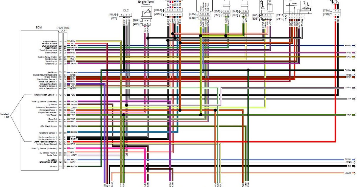
The wiring diagram includes color-coded wires, connector pinouts, and a legend to aid in tracing connections and identifying potential faults. By understanding the wiring diagram, technicians can effectively isolate issues, such as broken wires, loose connections, or faulty sensor components, allowing for swift repairs and minimizing downtime.
The Harley Twist Grip Sensor Wiring Diagram plays a crucial role in ensuring proper communication between the throttle control and the motorcycle’s electronic systems. Understanding its various aspects is essential for troubleshooting, repair, and overall motorcycle maintenance.
- Wiring Scheme: Outlines the electrical connections and pathways within the twist grip sensor assembly.
- Sensor Operation: Explains the working principles of the sensor, including how it converts throttle position into electrical signals.
- Connector Pinouts: Identifies the specific terminals on the sensor’s electrical connector and their corresponding functions.
- Color-Coded Wires: Facilitates easy identification and tracing of wires based on their designated colors.
- Diagnostic Procedures: Provides guidance on testing and diagnosing common issues related to the twist grip sensor.
- Troubleshooting Guide: Offers a step-by-step approach to isolating and resolving electrical faults within the wiring diagram.
- Compatibility Information: Specifies the motorcycle models and years to which the particular wiring diagram applies.
- Safety Precautions: Emphasizes the importance of following proper safety measures when working with electrical systems.
- Reference Guide: Serves as a quick reference for technicians and enthusiasts, providing essential information at a glance.
- Technical Specifications: Documents the electrical characteristics, tolerances, and operating parameters of the twist grip sensor.
These aspects collectively provide a comprehensive understanding of the Harley Twist Grip Sensor Wiring Diagram, enabling effective troubleshooting, repair, and maintenance of the motorcycle’s throttle control system. By referencing the wiring diagram and understanding its key components, technicians can ensure optimal performance and safety.
Wiring Scheme
Within the comprehensive blueprint of the Harley Twist Grip Sensor Wiring Diagram, the wiring scheme stands as a crucial component, mapping out the intricate network of electrical connections and pathways that govern the twist grip sensor assembly. By deciphering this scheme, technicians and enthusiasts gain a profound understanding of the sensor’s internal workings and its seamless integration with the motorcycle’s electronic systems.
- Circuit Layout: The wiring scheme unveils the precise arrangement of electrical circuits within the twist grip sensor assembly, detailing the flow of current through various components. This layout serves as a roadmap for troubleshooting, enabling technicians to trace connections, identify potential breaks, and pinpoint faulty components.
- Wire Color Coding: To facilitate efficient wire identification and tracing, the wiring scheme employs a standardized color-coding system. Each wire is assigned a unique color, corresponding to its specific function or connection point. This color-coding scheme simplifies the process of deciphering the wiring diagram and expedites repairs.
- Connector Pinouts: The wiring scheme meticulously documents the pinouts of the electrical connectors associated with the twist grip sensor assembly. These pinouts specify the exact location and function of each pin within the connector, ensuring proper mating and preventing misconnections.
- Signal Pathways: Beyond the physical connections, the wiring scheme also elucidates the pathways of electrical signals within the twist grip sensor assembly. It reveals how sensor inputs are converted into electrical signals and how these signals are transmitted to the motorcycle’s electronic control unit (ECU) for processing.
In summary, the wiring scheme within the Harley Twist Grip Sensor Wiring Diagram empowers technicians and enthusiasts with a comprehensive blueprint of the sensor’s electrical architecture. By understanding the circuit layout, wire color coding, connector pinouts, and signal pathways, they gain the knowledge necessary to diagnose, repair, and maintain the twist grip sensor assembly, ensuring optimal performance and safety.
Sensor Operation
Within the intricate tapestry of the Harley Twist Grip Sensor Wiring Diagram, the sensor operation stands as a pivotal element, orchestrating the conversion of throttle position into electrical signals that govern the motorcycle’s performance. Understanding the intricacies of sensor operation empowers technicians and enthusiasts alike to delve into the heart of the throttle control system, enabling them to diagnose, repair, and optimize its functionality.
- Throttle Position Sensing Mechanism: At the core of sensor operation lies the mechanism responsible for detecting the rider’s throttle input. This mechanism, typically employing a potentiometer or Hall effect sensor, translates the physical rotation of the throttle grip into a corresponding electrical signal.
- Signal Conditioning and Processing: The raw electrical signal generated by the throttle position sensing mechanism undergoes conditioning and processing to refine its accuracy and compatibility with the motorcycle’s electronic control unit (ECU). This process may involve amplification, filtering, and conversion to digital format.
- ECU Integration: The conditioned electrical signal is then transmitted to the ECU, the motorcycle’s central processing unit. The ECU interprets the signal, calculates the appropriate fuel injection and ignition timing, and adjusts the engine’s performance accordingly.
- Closed-Loop Control: The sensor operation is part of a closed-loop control system, ensuring precise throttle response and optimal engine performance. The ECU continuously monitors the engine’s operating parameters and adjusts the throttle position based on feedback from various sensors, including the twist grip sensor.
By comprehending the sensor operation within the Harley Twist Grip Sensor Wiring Diagram, technicians and enthusiasts gain a profound understanding of the throttle control system’s inner workings. This knowledge empowers them to diagnose and resolve sensor-related issues, ensuring that the motorcycle operates at its peak performance and efficiency.
Connector Pinouts
Within the intricate web of the Harley Twist Grip Sensor Wiring Diagram, connector pinouts emerge as a critical aspect, providing a comprehensive roadmap to the electrical connections within the twist grip sensor assembly. Understanding these pinouts empowers technicians and enthusiasts to navigate the sensor’s electrical interface, enabling them to diagnose, repair, and optimize its functionality.
- Terminal Identification: Connector pinouts meticulously document the specific terminals on the sensor’s electrical connector, assigning each terminal a unique identifier. These identifiers, typically numbers or letters, correspond to the terminal’s physical location within the connector.
- Function Mapping: Beyond mere identification, connector pinouts also map the corresponding functions of each terminal. This mapping details the purpose of each terminal, such as power supply, ground connection, or signal transmission, ensuring proper wiring and avoiding misconnections.
- Wiring Compatibility: Accurate connector pinouts are essential for ensuring compatibility between the twist grip sensor and its mating connector on the motorcycle’s wiring harness. By referencing the pinouts, technicians can verify that the wires are connected to the correct terminals, preventing electrical faults and ensuring optimal sensor performance.
- Diagnostic Tool: In the event of electrical issues or sensor malfunctions, connector pinouts serve as a valuable diagnostic tool. By testing the voltage or resistance at specific terminals, technicians can isolate the source of the problem, expediting the repair process and minimizing downtime.
In summary, connector pinouts within the Harley Twist Grip Sensor Wiring Diagram provide a comprehensive reference for understanding the electrical interface of the twist grip sensor assembly. Armed with this knowledge, technicians and enthusiasts can confidently diagnose, repair, and optimize the sensor’s functionality, ensuring the motorcycle’s smooth and responsive throttle control.
Color-Coded Wires
Within the intricate schematic of the Harley Twist Grip Sensor Wiring Diagram, color-coded wires emerge as a critical component, playing a pivotal role in simplifying the identification and tracing of electrical connections. This standardized color-coding system streamlines the process of troubleshooting, repair, and maintenance, empowering technicians and enthusiasts to navigate the wiring harness with precision and efficiency.
The color-coding scheme employed in the Harley Twist Grip Sensor Wiring Diagram is meticulously designed to align with industry standards and best practices. Each wire is assigned a unique color, corresponding to its specific function or connection point. This color-coding facilitates quick and accurate identification, eliminating the need for time-consuming trial-and-error methods or the use of additional testing equipment.
For instance, in many Harley-Davidson motorcycle models, red wires are typically designated for power supply, black wires for ground connections, and yellow wires for signal transmission. By simply observing the color of a wire, technicians can instantly determine its purpose and trace its path through the wiring harness, expediting the diagnosis and resolution of electrical issues.
The practical applications of understanding the color-coded wires within the Harley Twist Grip Sensor Wiring Diagram extend beyond mere convenience. Accurate wire identification ensures proper connections during assembly, reducing the risk of electrical faults and potential safety hazards. It also simplifies the process of modifying or customizing the wiring harness, allowing technicians to confidently make changes without compromising the integrity of the electrical system.
In summary, the color-coded wires within the Harley Twist Grip Sensor Wiring Diagram serve as an invaluable tool for troubleshooting, repair, and maintenance. The standardized color-coding system facilitates easy identification and tracing of wires, streamlines electrical diagnostics, and enhances the overall safety and reliability of the motorcycle’s electrical system.
Diagnostic Procedures
Within the comprehensive framework of the Harley Twist Grip Sensor Wiring Diagram, diagnostic procedures emerge as an integral component, offering invaluable guidance on testing and diagnosing common issues related to the twist grip sensor. These procedures empower technicians and enthusiasts to pinpoint and resolve sensor malfunctions, ensuring optimal performance and reliability of the motorcycle’s throttle control system.
The diagnostic procedures outlined in the wiring diagram provide a step-by-step approach to troubleshooting electrical faults and sensor-related problems. By following these procedures, technicians can systematically eliminate potential causes and identify the root of the issue. This structured approach saves time and effort compared to random trial-and-error methods, leading to effective and efficient repairs.
Real-life examples of diagnostic procedures within the Harley Twist Grip Sensor Wiring Diagram include testing the sensor’s resistance, voltage output, and signal continuity. These tests help determine whether the sensor is functioning properly or if there are electrical issues within the wiring harness or sensor assembly.
Understanding these diagnostic procedures is crucial for maintaining the proper operation of the twist grip sensor and the overall safety of the motorcycle. By utilizing the guidance provided in the wiring diagram, technicians can confidently troubleshoot and repair sensor-related issues, restoring the throttle control system to its optimal performance.
In summary, the diagnostic procedures within the Harley Twist Grip Sensor Wiring Diagram serve as an indispensable tool for diagnosing and resolving common sensor issues. These procedures empower technicians and enthusiasts to identify and fix electrical faults, ensuring the reliable and responsive operation of the motorcycle’s throttle control system.
Troubleshooting Guide
Within the intricate network of the Harley Twist Grip Sensor Wiring Diagram, the troubleshooting guide emerges as a pivotal tool, providing a structured and systematic approach to diagnosing and resolving electrical faults. Its significance lies in the fact that a thorough understanding of the wiring diagram is crucial for effective troubleshooting, enabling technicians and enthusiasts to pinpoint the root cause of electrical issues and implement appropriate repair strategies.
Real-life examples of the troubleshooting guide’s application within the Harley Twist Grip Sensor Wiring Diagram include:
- Diagnosing intermittent signal loss by testing wire continuity and identifying loose connections or damaged wires.
- Identifying faulty sensor components by comparing sensor output readings with specified values and replacing defective components as necessary.
- Resolving electrical shorts by tracing wires for breaks or insulation damage and repairing or replacing affected wires.
The practical applications of understanding the troubleshooting guide within the Harley Twist Grip Sensor Wiring Diagram extend beyond mere repair. It empowers technicians and enthusiasts to:
- Perform preventive maintenance by regularly inspecting the wiring harness for potential issues, reducing the risk of electrical failures.
- Customize or modify the wiring harness to accommodate specific electrical accessories or performance upgrades, ensuring compatibility and safe operation.
- Effectively communicate with other technicians or experts when seeking assistance with electrical troubleshooting, using a common language and understanding of the wiring diagram.
In summary, the troubleshooting guide within the Harley Twist Grip Sensor Wiring Diagram is an indispensable resource for diagnosing and resolving electrical faults, ensuring the optimal performance and reliability of the motorcycle’s throttle control system. Its systematic approach, real-life applications, and practical significance make it an essential tool for both professional technicians and motorcycle enthusiasts.
Compatibility Information
Within the realm of “Harley Twist Grip Sensor Wiring Diagram,” compatibility information stands as a critical component, playing a pivotal role in ensuring the accurate application of the wiring diagram to specific motorcycle models and years. This information serves as a guide for technicians, enthusiasts, and professionals, enabling them to determine whether the particular wiring diagram is compatible with their specific motorcycle, preventing potential electrical issues and ensuring optimal performance.
Real-life examples of compatibility information within the “Harley Twist Grip Sensor Wiring Diagram” include:
- Specifying compatibility with Harley-Davidson Sportster models from 2004 to 2013.
- Indicating compatibility with Harley-Davidson Softail models from 2011 to 2017.
- Identifying compatibility with Harley-Davidson Touring models from 2014 onwards.
Understanding the compatibility information within the “Harley Twist Grip Sensor Wiring Diagram” offers several practical applications:
- Prevents electrical issues: Using a compatible wiring diagram ensures that the electrical connections and components match the specific motorcycle model and year, preventing electrical faults, shorts, or damage to sensitive electronic components.
- Ensures optimal performance: A compatible wiring diagram guarantees that the twist grip sensor is properly integrated with the motorcycle’s electronic control unit (ECU), resulting in accurate throttle response, smooth engine operation, and optimal fuel efficiency.
- Facilitates troubleshooting and repair: When troubleshooting electrical issues or performing repairs, having the correct wiring diagram for the specific motorcycle model and year allows technicians to accurately trace wires, identify components, and resolve problems efficiently.
In summary, the compatibility information within the “Harley Twist Grip Sensor Wiring Diagram” is a crucial aspect that ensures the proper application and effectiveness of the wiring diagram. By aligning the wiring diagram with the specific motorcycle model and year, technicians and enthusiasts can confidently perform electrical work, maintain optimal performance, and ensure the safe and reliable operation of their Harley-Davidson motorcycle.
Safety Precautions
Within the realm of “Harley Twist Grip Sensor Wiring Diagram,” safety precautions emerge as a paramount aspect, guiding technicians and enthusiasts alike towards a safe and responsible approach when handling electrical systems. Understanding and adhering to these precautions is not merely an option but an imperative, ensuring the well-being of individuals and safeguarding the integrity of electrical components.
- Electrical Hazards: Working with electrical systems poses inherent risks, including shock, burns, and even electrocution. Safety precautions emphasize the importance of recognizing these hazards and taking appropriate measures to mitigate them.
- Protective Equipment: Before embarking on any electrical work, it is crucial to don appropriate protective equipment, such as insulated gloves, safety glasses, and non-conductive footwear. These safeguards minimize the risk of electrical shock and protect against potential hazards.
- Electrical Isolation: Prior to commencing work on electrical components, it is essential to isolate the power source by disconnecting the battery or removing fuses. This step eliminates the risk of accidental energization and ensures a safe working environment.
- Proper Tools: Utilizing the correct tools for electrical work is paramount. Insulated tools prevent accidental contact with live wires, reducing the risk of shock. Additionally, specialized tools designed for electrical applications ensure precision and minimize the likelihood of damage to components.
By adhering to these safety precautions, individuals can confidently perform electrical work on “Harley Twist Grip Sensor Wiring Diagram” and other related systems, ensuring their personal safety and the integrity of the electrical components involved. Neglecting safety measures can lead to severe consequences, underscoring the importance of prioritizing safety at all times.
Reference Guide
Within the context of the “Harley Twist Grip Sensor Wiring Diagram,” the reference guide emerges as an indispensable component, fulfilling a critical role in providing quick and convenient access to essential information for technicians and enthusiasts alike. Its significance lies in its ability to streamline troubleshooting, repair, and maintenance processes, ensuring efficient and effective work.
The reference guide within the “Harley Twist Grip Sensor Wiring Diagram” typically encompasses a concise yet comprehensive compilation of key data, including:
- Wiring schematics illustrating the electrical connections and components of the twist grip sensor assembly.
- Technical specifications outlining the sensor’s operating parameters, such as voltage range, resistance, and signal output.
- Diagnostic procedures guiding technicians through step-by-step troubleshooting methodologies to identify and resolve common sensor issues.
- Compatibility information specifying the motorcycle models and years to which the wiring diagram applies.
By having this essential information readily available in a single, easy-to-access reference guide, technicians and enthusiasts can:
- Quickly identify and locate specific wires, connectors, and components within the twist grip sensor assembly.
- Accurately diagnose sensor malfunctions by comparing measured values against specified parameters.
- Efficiently resolve electrical issues by following structured troubleshooting procedures.
- Confidently modify or customize the wiring harness based on compatibility information.
In summary, the reference guide within the “Harley Twist Grip Sensor Wiring Diagram” serves as a valuable tool, empowering technicians and enthusiasts with the essential information they need to effectively troubleshoot, repair, and maintain the motorcycle’s throttle control system. Its practical significance lies in its ability to streamline electrical work, reduce downtime, and ensure the safe and reliable operation of the motorcycle.
Technical Specifications
Within the comprehensive framework of the “Harley Twist Grip Sensor Wiring Diagram,” technical specifications emerge as a critical component, providing a detailed blueprint of the electrical characteristics, tolerances, and operating parameters of the twist grip sensor. These specifications serve as a foundation for understanding the sensor’s functionality, ensuring accurate installation, and enabling effective troubleshooting and repair.
- Electrical Characteristics: This section documents the sensor’s voltage range, current draw, and resistance values. Understanding these characteristics is crucial for selecting compatible electrical components and ensuring proper sensor operation within the motorcycle’s electrical system.
- Tolerances: Technical specifications outline the acceptable range of variation for the sensor’s electrical parameters. These tolerances account for manufacturing variability and environmental factors, ensuring that the sensor meets performance expectations under various operating conditions.
- Operating Parameters: This section specifies the temperature range, vibration resistance, and other environmental factors that the sensor is designed to withstand. Understanding these parameters is essential for ensuring the sensor’s reliability and durability in real-world riding conditions.
- Sensor Output: Technical specifications provide details on the sensor’s output signal type, voltage levels, and linearity. This information is crucial for interfacing the sensor with the motorcycle’s electronic control unit (ECU) and ensuring accurate throttle control.
In summary, the technical specifications within the “Harley Twist Grip Sensor Wiring Diagram” provide a comprehensive understanding of the twist grip sensor’s electrical characteristics, tolerances, and operating parameters. By adhering to these specifications, technicians and enthusiasts can ensure the proper installation, operation, and maintenance of the throttle control system, maximizing the motorcycle’s performance, safety, and reliability.


Related Posts


