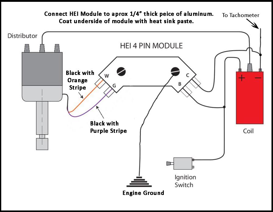
A GM HEI distributor wiring diagram is a schematic representation of the electrical connections within a General Motors High Energy Ignition (HEI) distributor. It outlines the flow of current through the distributor’s components, enabling proper installation, troubleshooting, and repair of the ignition system.
This wiring diagram guides the connection of the distributor’s pickup coil, ignition coil, module, and other electrical components. Understanding this diagram ensures that the ignition system functions optimally, providing reliable spark delivery to the engine’s cylinders.
The development of the HEI distributor was a significant advancement in automotive ignition systems. It replaced the traditional points-based ignition with an electronic module, resulting in improved spark intensity, reduced maintenance requirements, and enhanced engine performance. This wiring diagram plays a crucial role in understanding the intricacies of the HEI distributor, facilitating its effective diagnosis and maintenance.
Understanding the essential aspects of a GM HEI distributor wiring diagram is paramount for effective ignition system diagnosis and maintenance. These key aspects, intricately connected to the diagram’s function as a schematic representation, provide a comprehensive framework for comprehending the electrical connections within the distributor.
- Circuitry: The wiring diagram outlines the electrical pathways, enabling the flow of current through the distributor’s components.
- Components: It identifies the specific electrical components, such as the pickup coil, ignition coil, and module, and their respective connections.
- Connections: The diagram precisely depicts the wire connections between the distributor’s internal components and external wiring harness.
- Polarity: It indicates the proper orientation of electrical connections, ensuring correct polarity for optimal performance.
- Grounding: The diagram specifies the grounding points for the distributor’s electrical system, crucial for proper circuit completion.
- Shielding: It may include details on shielding techniques to minimize electrical interference and ensure reliable signal transmission.
- Troubleshooting: The wiring diagram serves as a valuable tool for troubleshooting ignition system issues, aiding in the identification of faulty connections or components.
- Reference: It provides a visual reference for electrical system modifications or upgrades, ensuring compatibility and proper functionality.
- Compatibility: The diagram specifies the compatibility of the wiring harness with specific HEI distributor models.
In summary, these key aspects collectively define the GM HEI distributor wiring diagram, providing a comprehensive understanding of its electrical connections and enabling effective diagnosis, maintenance, and modification of the ignition system.
Circuitry
Within the comprehensive framework of a GM HEI distributor wiring diagram, the circuitry aspect plays a pivotal role in defining the electrical connections and current flow within the distributor. By outlining the specific electrical pathways, the wiring diagram provides a roadmap for understanding how current travels through the distributor’s components, ensuring optimal performance and efficient ignition.
- Electrical Components: The wiring diagram identifies the electrical components within the distributor, such as the pickup coil, ignition coil, and module, and specifies their respective connections. This information is crucial for understanding the functionality of each component and its contribution to the ignition process.
- Current Flow: The diagram illustrates the direction of current flow through the distributor’s components, enabling technicians to trace the electrical pathways and identify potential issues. This knowledge is essential for troubleshooting ignition problems and ensuring proper spark delivery to the engine’s cylinders.
- Polarity and Grounding: The wiring diagram specifies the correct polarity of electrical connections and identifies grounding points within the distributor. Proper polarity and grounding are critical for ensuring optimal circuit performance and preventing electrical malfunctions.
- Compatibility and Modifications: The wiring diagram provides information on the compatibility of the wiring harness with specific HEI distributor models. Additionally, it may include details on potential modifications or upgrades to the ignition system, allowing for tailored performance and customization.
In conclusion, the circuitry aspect of a GM HEI distributor wiring diagram is fundamental to understanding the electrical connections and current flow within the distributor. It serves as a valuable tool for troubleshooting, maintenance, and modification of the ignition system, ensuring reliable engine performance and efficient spark delivery.
Components
Within the intricate network of a GM HEI distributor wiring diagram, the identification of specific electrical components and their respective connections holds paramount importance. This aspect provides a comprehensive understanding of the distributor’s internal workings, enabling effective troubleshooting, maintenance, and performance optimization.
-
Pickup Coil:
The pickup coil, a vital component within the HEI distributor, generates an electrical signal proportional to the distributor shaft’s rotational speed. This signal triggers the ignition module to initiate spark delivery, ensuring precise timing and optimal engine performance. -
Ignition Coil:
The ignition coil amplifies the electrical signal from the ignition module, generating a high-voltage pulse that travels to the spark plugs. This high-voltage pulse creates the spark necessary to ignite the air-fuel mixture within the engine’s cylinders, driving the combustion process. -
Ignition Module:
The ignition module serves as the brain of the HEI distributor, processing signals from the pickup coil and controlling the ignition coil’s operation. It determines the timing and duration of spark delivery, optimizing engine performance across various operating conditions. -
Distributor Cap and Rotor:
The distributor cap and rotor work in conjunction to distribute the high-voltage pulses from the ignition coil to the appropriate spark plugs in the engine’s firing order. Proper cap and rotor condition is crucial for maintaining optimal spark delivery and preventing ignition system malfunctions.
In summary, understanding the electrical components of a GM HEI distributor and their respective connections, as outlined in the wiring diagram, is essential for comprehensive ignition system diagnosis, maintenance, and performance enhancement. By identifying and comprehending the roles of these components, technicians can effectively troubleshoot issues, ensure reliable spark delivery, and optimize engine operation.
Connections
Within the comprehensive framework of a GM HEI distributor wiring diagram, understanding the wire connections between the distributor’s internal components and external wiring harness is of paramount importance. These connections form the backbone of the ignition system, ensuring proper communication and power distribution throughout the circuit. By precisely depicting these connections, the wiring diagram provides a roadmap for troubleshooting, maintenance, and performance optimization.
-
Internal Components:
The wiring diagram identifies the specific electrical components within the distributor, such as the pickup coil, ignition coil, and ignition module, and outlines their respective wire connections. This information is crucial for understanding the functionality of each component and its contribution to the ignition process. -
External Wiring Harness:
The wiring diagram specifies the connections between the distributor and the external wiring harness, which links the distributor to the vehicle’s electrical system. This includes connections to the battery, ignition switch, and other electrical modules, ensuring proper power supply and signal transmission. -
Polarity and Grounding:
The wiring diagram indicates the correct polarity and grounding points for the distributor’s electrical connections. Proper polarity and grounding are critical for optimal circuit performance and preventing electrical malfunctions, ensuring reliable spark delivery and ignition timing. -
Compatibility and Modifications:
The wiring diagram provides information on the compatibility of the wiring harness with specific HEI distributor models. Additionally, it may include details on potential modifications or upgrades to the ignition system, allowing for tailored performance and customization.
In summary, the precise depiction of wire connections between the distributor’s internal components and external wiring harness in a GM HEI distributor wiring diagram is fundamental to understanding the ignition system’s functionality. This information enables effective troubleshooting, maintenance, and performance optimization, ensuring reliable engine performance and efficient spark delivery.
Polarity
Within the intricate network of a GM HEI distributor wiring diagram, understanding the significance of polarity and adhering to the proper orientation of electrical connections is of utmost importance. Polarity dictates the direction of current flow within the circuit, directly impacting the distributor’s and the overall ignition process. By ensuring correct polarity, optimal performance and reliable spark delivery can be achieved.
- Electrical Components: Polarity plays a crucial role in the proper functioning of electrical components within the distributor, such as the pickup coil, ignition coil, and ignition module. Incorrect polarity can disrupt the intended flow of current, leading to component malfunctions and potential damage.
- Circuit Functionality: The overall functionality of the ignition circuit relies heavily on correct polarity. Reversing polarity can lead to incorrect triggering of the ignition module, resulting in misfiring, poor engine performance, and increased emissions.
- Grounding: Establishing proper grounding connections with correct polarity is essential for completing the electrical circuit and ensuring a stable reference point for current flow. Incorrect grounding can cause erratic behavior, ignition system malfunctions, and potential electrical hazards.
- Troubleshooting: Understanding polarity is invaluable during troubleshooting procedures. Identifying and correcting polarity issues can help isolate electrical faults, pinpoint faulty components, and restore optimal ignition system operation.
In summary, adhering to the proper polarity of electrical connections, as indicated in a GM HEI distributor wiring diagram, is paramount for ensuring optimal performance, preventing malfunctions, and maintaining a reliable ignition system. Correct polarity allows for the intended flow of current, proper functioning of electrical components, and efficient spark delivery, resulting in smooth engine operation and enhanced overall vehicle performance.
Grounding
Within the intricate web of a GM HEI distributor wiring diagram, grounding holds a pivotal position, ensuring the proper completion of electrical circuits and the smooth operation of the distributor. Grounding provides a stable reference point for current flow, allowing for the proper functioning of electrical components and the precise delivery of spark to the engine’s cylinders.
The grounding points specified in the wiring diagram are carefully chosen to minimize electrical resistance and ensure a reliable connection to the vehicle’s chassis. This low-resistance path allows excess current or voltage to safely dissipate, preventing damage to electrical components and ensuring optimal performance.
Without proper grounding, the distributor’s electrical system would be incomplete, leading to erratic behavior, ignition malfunctions, and potential electrical hazards. The wiring diagram provides a clear understanding of the grounding points, enabling technicians to verify proper connections and troubleshoot any grounding issues that may arise.
In practical applications, grounding plays a critical role in maintaining a stable and reliable ignition system. Loose or corroded grounding connections can lead to intermittent spark, engine misfires, and reduced overall performance. By referring to the grounding points specified in the wiring diagram, technicians can quickly identify and resolve grounding issues, ensuring optimal ignition system operation.
In summary, the grounding points specified in a GM HEI distributor wiring diagram are essential for establishing a complete electrical circuit, providing a stable reference for current flow, and preventing electrical malfunctions. Understanding the importance of proper grounding and adhering to the grounding points outlined in the wiring diagram is crucial for maintaining a reliable and efficient ignition system.
Shielding
Within the intricate network of a GM HEI distributor wiring diagram, shielding plays a crucial role in mitigating electrical interference and ensuring reliable signal transmission, which are vital for precise ignition timing and optimal engine performance. The wiring diagram may provide details on specific shielding techniques and components employed to minimize electromagnetic noise and maintain signal integrity.
-
EMI Suppression:
Electrical interference, often referred to as electromagnetic interference (EMI), can disrupt the proper functioning of the distributor’s electronic components. Shielding techniques, such as the use of shielded wires and grounded metal enclosures, help suppress EMI, minimizing its impact on the distributor’s operation. -
Grounding:
Proper grounding is essential for effective shielding. The wiring diagram specifies grounding points for the distributor and its components, ensuring a low-resistance path to dissipate unwanted electrical noise and minimize interference. -
Component Shielding:
Specific electrical components within the distributor, such as the pickup coil and ignition module, may be shielded to minimize their susceptibility to electrical interference. Shielding enclosures or conductive coatings help protect these components from external noise, ensuring reliable signal transmission. -
Wire Routing:
The wiring diagram may include recommendations for routing the distributor’s wiring harness to minimize exposure to sources of electrical interference, such as spark plug wires or other electrical components. Proper wire routing helps maintain signal integrity and prevents cross-talk between circuits.
In summary, the shielding techniques and components outlined in a GM HEI distributor wiring diagram are crucial for minimizing electrical interference and ensuring reliable signal transmission. By understanding and adhering to these shielding measures, technicians can optimize the distributor’s performance, ensuring precise ignition timing and efficient engine operation.
Troubleshooting
Within the intricacies of a GM HEI distributor wiring diagram lies a powerful tool for troubleshooting ignition system issues, enabling technicians to pinpoint faulty connections or components with precision. By understanding the electrical pathways and component interconnections outlined in the diagram, technicians can systematically diagnose and rectify ignition system malfunctions, ensuring optimal engine performance and reliable operation.
- Electrical Continuity Testing: The wiring diagram provides a roadmap for conducting electrical continuity tests, allowing technicians to verify the integrity of electrical connections and identify open circuits or high-resistance points. By systematically checking for continuity along the specified wiring paths, technicians can isolate faulty wires, connectors, or components.
- Component Isolation: The diagram facilitates the isolation of individual electrical components for testing and replacement. By following the wiring connections, technicians can disconnect and test specific components, such as the pickup coil, ignition module, or distributor cap, to determine their functionality and identify potential faults.
- Voltage and Signal Analysis: Armed with the wiring diagram, technicians can measure voltage and signal waveforms at various points in the ignition circuit. Comparing measured values to specifications allows them to identify deviations that indicate faulty components or improper system operation.
- Diagnostic Procedures: Many wiring diagrams include diagnostic procedures or troubleshooting trees that guide technicians through a series of tests and measurements to pinpoint the source of ignition system issues. By following these procedures, technicians can efficiently narrow down the potential causes and identify the necessary repairs.
In summary, the troubleshooting aspect of a GM HEI distributor wiring diagram empowers technicians with a structured approach to diagnosing and resolving ignition system issues. By understanding the electrical connections and component interdependencies outlined in the diagram, technicians can effectively isolate faulty components, identify electrical faults, and restore optimal ignition system operation.
Reference
Within the realm of GM HEI distributor wiring diagrams, the reference aspect serves as a critical component, guiding electrical system modifications and upgrades with precision and confidence. By providing a visual representation of the distributor’s electrical connections, the wiring diagram empowers technicians and enthusiasts alike to make informed decisions regarding system enhancements.
The reference aspect of the wiring diagram enables users to visualize the potential impact of modifications or upgrades before implementing them. This forethought helps ensure compatibility between new components and the existing electrical system, minimizing the risk of malfunctions or damage. Moreover, the diagram provides insights into the proper functionality of the modified system, ensuring optimal performance and reliability.
For instance, when upgrading the ignition coil in a GM HEI distributor, the wiring diagram serves as a guide to selecting a compatible coil with the appropriate resistance and voltage requirements. By adhering to the specified wiring connections, technicians can avoid potential issues such as incorrect spark timing or excessive current draw that could compromise the system’s integrity.
The practical significance of understanding this reference aspect extends to various applications. From basic maintenance procedures to advanced performance modifications, the wiring diagram serves as an invaluable resource for ensuring the compatibility and proper functionality of the GM HEI distributor ignition system. By empowering users with a deeper understanding of the electrical connections, the wiring diagram facilitates informed decision-making, reduces troubleshooting time, and ultimately enhances overall vehicle performance.
Compatibility
Within the intricate web of a GM HEI distributor wiring diagram, compatibility plays a pivotal role, ensuring seamless integration and optimal performance when replacing or upgrading the ignition system. The wiring diagram provides precise information on the compatibility of the wiring harness with specific HEI distributor models, empowering technicians and enthusiasts to make informed decisions and achieve desired outcomes.
-
Matching Electrical Characteristics:
The wiring diagram specifies the electrical characteristics of the wiring harness, including voltage requirements and current capacity. This information is crucial for ensuring compatibility with the specific HEI distributor model, preventing potential damage or malfunctions due to mismatched electrical parameters.
-
Connector Compatibility:
The wiring diagram details the types of connectors used in the wiring harness and their compatibility with the HEI distributor. Matching connectors ensure a secure and reliable electrical connection, preventing intermittent signals or power loss that could affect ignition performance.
-
Physical Compatibility:
The wiring diagram provides insights into the physical dimensions and mounting points of the wiring harness. This information helps determine if the harness can be accommodated within the available space and properly connected to the HEI distributor, avoiding installation issues or potential interference with other components.
-
Functional Compatibility:
The wiring diagram outlines the functional compatibility of the wiring harness with the HEI distributor model. It specifies the supported features and capabilities, ensuring that the harness can accommodate the desired functionalities, such as electronic spark timing control or tachometer outputs.
Understanding the compatibility aspect of a GM HEI distributor wiring diagram is paramount for successful ignition system upgrades or replacements. By adhering to the specified compatibility guidelines, technicians can avoid costly mistakes, ensure proper functionality, and achieve optimal engine performance. The wiring diagram serves as a valuable reference, empowering users to make informed decisions and confidently navigate the complexities of ignition system compatibility.


Related Posts


