A KLR 650 wiring diagram provides a comprehensive visual representation of the electrical connections and components within a Kawasaki KLR 650 motorcycle. It serves as a guide for understanding the electrical system, troubleshooting issues, and performing maintenance.
Wiring diagrams are crucial for diagnosing electrical problems. By tracing the connections on the diagram, technicians can identify open or short circuits, faulty components, and incorrect wire routing. This information allows them to repair or replace the affected components, restoring the motorcycle’s electrical system to proper operation.
One key historical development in wiring diagrams is the advent of computer-aided design (CAD) software. CAD tools allow engineers to create detailed and accurate diagrams that are easy to read and interpret. These diagrams have significantly improved the efficiency and accuracy of motorcycle electrical system design and troubleshooting.
Understanding the essential aspects of a KLR 650 wiring diagram is paramount for comprehending the electrical system of this motorcycle. These aspects provide insights into the design, functionality, and maintenance of the wiring system.
- Components: A wiring diagram identifies all electrical components in the system, such as the battery, ignition switch, lights, and sensors.
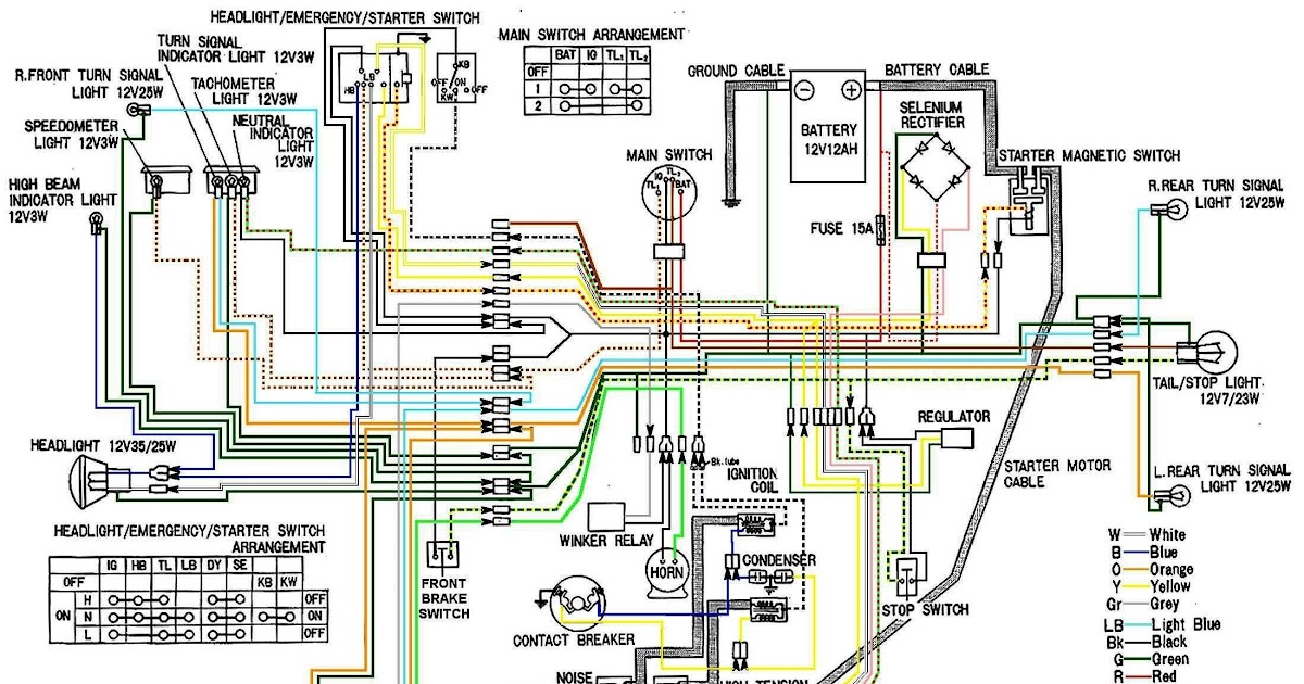
- Connections: It shows how these components are interconnected, including the type of connectors used and the wire colors.
- Circuits: The diagram depicts the electrical circuits, allowing for tracing of current flow and identification of potential faults.
- Grounding: It indicates the grounding points in the system, which are essential for proper electrical function and safety.
- Fuses and relays: The diagram shows the location and function of fuses and relays, which protect the electrical system from overloads.
- Troubleshooting: Wiring diagrams are invaluable for troubleshooting electrical problems, as they allow technicians to pinpoint the source of issues.
- Modifications: They provide a reference for making modifications to the electrical system, such as adding accessories or upgrading components.
- Maintenance: Wiring diagrams assist in performing maintenance tasks, such as inspecting connections, testing components, and replacing faulty wires.
These aspects collectively provide a comprehensive understanding of the KLR 650 wiring diagram, enabling effective diagnosis, repair, and maintenance of the motorcycle’s electrical system.
Components
In the context of a KLR 650 wiring diagram, understanding the individual components is essential for comprehending the overall electrical system of the motorcycle. The wiring diagram serves as a map, identifying each electrical component and its location within the system. This information is crucial for troubleshooting electrical issues, performing maintenance, and making modifications.
For instance, if a rider experiences a problem with the motorcycle’s lighting system, they can refer to the wiring diagram to identify the specific components involved, such as the battery, light switch, and headlight. By tracing the connections between these components, they can determine whether the issue lies in a faulty component, a loose connection, or a wiring problem.
Furthermore, when performing maintenance tasks such as replacing a battery or upgrading lighting components, the wiring diagram provides a clear reference for identifying the correct connections and ensuring proper installation. This helps prevent electrical malfunctions and ensures the motorcycle’s electrical system operates safely and efficiently.
In summary, understanding the components identified in a KLR 650 wiring diagram is fundamental for diagnosing, maintaining, and modifying the motorcycle’s electrical system. It empowers riders and technicians to identify electrical issues, perform repairs, and make informed decisions regarding electrical upgrades.
Connections
In a KLR 650 wiring diagram, connections are the vital pathways that establish electrical communication between the various components, allowing for the proper functioning of the motorcycle’s electrical system. Each wire in the diagram represents a connection, and its color-coding provides a standardized method for identifying its purpose and tracing its path throughout the system.
For example, a red wire typically indicates a connection to the positive terminal of the battery, while a black wire usually represents a ground connection. Understanding these color-coding conventions is essential for correctly interpreting the wiring diagram and ensuring accurate troubleshooting and repairs.
The type of connectors used in the KLR 650 wiring diagram also plays a critical role in maintaining reliable electrical connections. Different connectors are designed for specific purposes, such as bullet connectors for quick and easy connections, spade connectors for secure connections to terminals, and multi-pin connectors for complex connections involving multiple wires.
Understanding the types of connectors used allows technicians to properly connect and disconnect components, ensuring that the electrical system operates safely and efficiently. Incorrect connections can lead to electrical malfunctions, component damage, or even safety hazards.
In summary, the connections identified in a KLR 650 wiring diagram are crucial for understanding the flow of electricity throughout the motorcycle’s electrical system. Color-coding conventions and the types of connectors used provide valuable information for troubleshooting, maintenance, and modifications, ensuring the proper and safe operation of the motorcycle.
Circuits
Within a KLR 650 wiring diagram, circuits are fundamental components that define the pathways for electrical current to flow throughout the motorcycle’s electrical system. Understanding these circuits is paramount for troubleshooting electrical issues, performing maintenance, and making modifications.
Each circuit in the diagram represents a specific function, such as the lighting circuit, ignition circuit, or charging circuit. By tracing the connections within each circuit, technicians can identify the components involved, the direction of current flow, and potential fault points.
For instance, if a rider experiences a problem with the motorcycle’s turn signals, they can refer to the wiring diagram to trace the turn signal circuit. This allows them to identify the components involved, such as the turn signal switch, flasher relay, and turn signal bulbs. By systematically checking the connections and components within this circuit, they can isolate the source of the issue, whether it’s a faulty bulb, a loose connection, or a problem with the turn signal switch.
Furthermore, when performing maintenance tasks such as replacing a battery or upgrading lighting components, the wiring diagram provides a clear reference for identifying the correct connections and ensuring that the new components are properly integrated into the electrical system.
In summary, the circuits identified in a KLR 650 wiring diagram are essential for understanding the flow of electricity within the motorcycle’s electrical system. They empower riders and technicians to troubleshoot electrical problems, perform repairs, and make informed decisions regarding electrical upgrades, ensuring the safe and efficient operation of the motorcycle.
Grounding
Within the context of a KLR 650 wiring diagram, grounding plays a crucial role in ensuring the proper and safe operation of the motorcycle’s electrical system. Grounding refers to the electrical connection of a circuit to a common reference point, typically the metal frame of the motorcycle. This connection provides a path for electrical current to flow back to the source, completing the circuit and allowing components to function correctly.
In a KLR 650 wiring diagram, grounding points are typically indicated by the symbol of a triangle connected to a horizontal line. These points represent the locations where electrical components are connected to the motorcycle’s frame or other grounding points. Understanding the grounding scheme is essential for troubleshooting electrical issues, as an improper or faulty ground connection can lead to a variety of problems.
For example, a loose or corroded ground connection can cause electrical components to malfunction or behave erratically. This can manifest in various ways, such as flickering lights, intermittent starting problems, or even electrical shorts. By referring to the wiring diagram and identifying the grounding points, technicians can check the integrity of these connections and ensure that they are clean and secure.
Furthermore, when making modifications to the electrical system, such as adding accessories or upgrading components, it is important to consider the grounding requirements of the new equipment. The wiring diagram provides valuable information about the appropriate grounding points for these additions, ensuring that they are properly integrated into the motorcycle’s electrical system and grounded according to the manufacturer’s specifications.
Fuses and relays
In the context of a KLR 650 Wiring Diagram, fuses and relays play a critical role in safeguarding the electrical system from potential damage caused by overloads. The wiring diagram provides valuable information about the location and function of these protective devices, empowering riders and technicians to troubleshoot electrical issues, perform maintenance, and make informed decisions regarding electrical upgrades.
- Fuse Types and Functions: Fuses are designed to interrupt the flow of electrical current when it exceeds a predetermined safe level. The wiring diagram indicates the type and amperage rating of each fuse, allowing technicians to identify the appropriate replacement fuse in case of a blown fuse.
- Relay Functions: Relays are electromagnetic switches that use a small amount of current to control a larger electrical load. The wiring diagram shows the location and function of each relay, enabling technicians to diagnose and repair relay-related issues.
- Circuit Protection: Fuses and relays work together to protect the electrical system from overloads. When an electrical fault occurs, the fuse will blow or the relay will open, interrupting the flow of current and preventing damage to sensitive electrical components.
- Maintenance and Troubleshooting: The wiring diagram provides guidance for inspecting and testing fuses and relays as part of regular maintenance. It also assists in troubleshooting electrical problems by indicating the circuits protected by each fuse or relay, narrowing down the potential causes of an electrical fault.
Understanding the location and function of fuses and relays, as depicted in a KLR 650 Wiring Diagram, is essential for ensuring the safe and reliable operation of the motorcycle’s electrical system. By referring to the wiring diagram, riders and technicians can effectively troubleshoot electrical issues, perform preventive maintenance, and make informed decisions regarding electrical upgrades, contributing to the overall performance and longevity of the motorcycle.
Troubleshooting
In the context of a KLR 650 Wiring Diagram, troubleshooting plays a crucial role in maintaining the motorcycle’s electrical system. Wiring diagrams serve as essential tools for technicians and riders alike, providing a systematic approach to identify and resolve electrical issues.
- Isolation and Identification: Wiring diagrams enable technicians to isolate and identify the specific circuit or component causing an electrical problem. By tracing the connections and components depicted in the diagram, they can narrow down the potential sources of the issue, reducing diagnostic time and effort.
- Visual Representation: The visual representation of the electrical system in a wiring diagram allows technicians to quickly assess the overall layout, component interconnections, and potential fault points. This comprehensive view facilitates a deeper understanding of the system’s functionality and aids in identifying potential problems.
- Systematic Approach: Wiring diagrams provide a structured and logical approach to troubleshooting. By following the connections and components in a systematic manner, technicians can eliminate potential causes and progressively isolate the source of the issue. This reduces the risk of overlooking or misdiagnosing problems, leading to more accurate and efficient repairs.
- Real-Life Examples: In real-life scenarios, wiring diagrams are indispensable for troubleshooting various electrical issues. For instance, if a rider encounters a problem with the motorcycle’s lighting system, the wiring diagram guides them in tracing the circuit, identifying potential loose connections, faulty bulbs, or switch malfunctions, enabling them to pinpoint the source of the problem and implement appropriate repairs.
In conclusion, the troubleshooting aspect of a KLR 650 Wiring Diagram is a valuable asset for diagnosing and resolving electrical problems. By providing a visual representation of the electrical system and a systematic approach to troubleshooting, wiring diagrams empower technicians to quickly identify and repair electrical issues, ensuring the safe and reliable operation of the motorcycle.
Modifications
Within the context of the KLR 650 Wiring Diagram, modifications play a significant role in tailoring the electrical system to suit specific needs and preferences. The wiring diagram serves as a crucial reference guide for riders and technicians seeking to modify their motorcycle’s electrical system, whether it involves adding accessories or upgrading components.
The KLR 650 Wiring Diagram provides a comprehensive overview of the motorcycle’s electrical system, including the location and function of each component, the routing of wires, and the connection points. This information is essential for understanding the existing electrical system and planning modifications accordingly.
Real-life examples of modifications that leverage the KLR 650 Wiring Diagram include:
- Accessory Installation: Riders may choose to install additional accessories such as heated grips, auxiliary lighting, or GPS systems. The wiring diagram helps identify suitable connection points and ensures proper integration with the existing electrical system.
- Component Upgrades: To enhance performance or reliability, riders may upgrade components such as the battery, alternator, or ignition system. The wiring diagram provides insights into the compatibility and electrical requirements of these upgrades.
Understanding the connection between modifications and the KLR 650 Wiring Diagram is crucial for safe and effective electrical system modifications. By carefully following the wiring diagram and adhering to recommended practices, riders and technicians can confidently make modifications that meet their specific needs while maintaining the integrity and functionality of the motorcycle’s electrical system.
Maintenance
Wiring diagrams play a critical role in the maintenance of a KLR 650’s electrical system, providing a comprehensive guide for performing various maintenance tasks. These tasks include inspecting connections, testing components, and replacing faulty wires, ensuring the motorcycle’s electrical system operates reliably and efficiently.
- Inspecting Connections: Wiring diagrams help identify and inspect electrical connections throughout the motorcycle. By visually examining the diagram, technicians can locate specific connections, check for loose or corroded terminals, and ensure proper wire routing. Regular inspections help prevent electrical problems and maintain optimal system performance.
- Testing Components: Wiring diagrams provide valuable information for testing electrical components. The diagram indicates the correct test points and procedures for measuring voltage, resistance, or continuity. By following the diagram’s instructions, technicians can accurately test components such as switches, sensors, and relays, identifying any faulty or malfunctioning parts.
- Replacing Faulty Wires: Wiring diagrams are essential for tracing and replacing faulty wires. The diagram shows the location and routing of each wire, allowing technicians to identify the damaged section and plan the replacement. By following the diagram’s guidance, they can ensure the new wire is correctly routed and connected, restoring the electrical system’s functionality.
In summary, wiring diagrams serve as invaluable tools for maintaining the KLR 650’s electrical system. They guide technicians through inspections, component testing, and wire replacement, enabling them to identify and resolve electrical issues effectively. Regular maintenance using wiring diagrams helps prevent electrical failures, ensures optimal system performance, and contributes to the overall safety and reliability of the motorcycle.


![[41+] Kawasaki Klr 650 Wiring Diagram, Gen 1 Ignition On Gen 2](https://i0.wp.com/c1.staticflickr.com/3/2729/32415968820_c3f5194442_o.jpg?w=665&ssl=1)
Related Posts


